Week -2
1) Make a Simulink model of Doorbell using solenoid block
- Create a situation where the switch is closed for 2 seconds and then released. Observe the physical movement of the plunger.
SOLUTION :
Representation of Door bell using solenoid block
- Here we have to make the pictorial representation of door bell that is shown above into simulink model by using the suitable blocks.
- The following are the suitable blocks that helps to build a simulink model of door bell uisng solenoid.
1) Pulse generator
2) S-PS conerter
3) switch
4)battery or voltage source
5) Electrical reference
6) Solver configuration
7) Solenoid
8) ideal translational motion sensor
9) PS-S convertor
10) scope
- For selecting the above blocks we should be through with the names of the blocks and their purpose.
- Next,we should connect the blocks as shown in the diagram below.
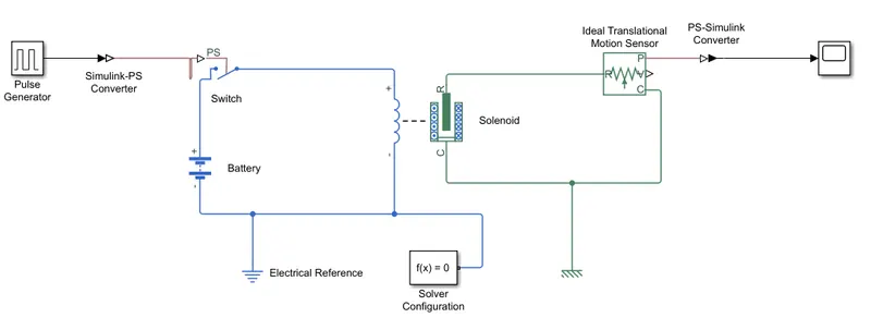
Block diagram of door bell using solenoid in simulunk
- After connecting the blocks the signal is to be given to pulse generator as per given conditions.
- Then the simulation process takes place and the striking of plunger is plotted in the graph through scope.
Result :
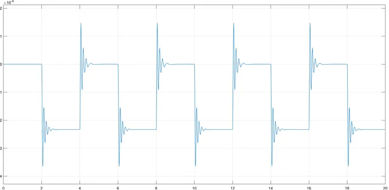 Simulation of doorbell signal
- The above graph represents the simulation results of output signal of door bell.
- The graph shows the generation of door bell signal when the switch is closed.
- Here we created a simulink block of door bell using simulink simulation from the given elctrical circuit.
- when switch is closed for 2 sec means amplitude=0 the currrent passes through the circuit and the plunger strikes for every 2 sec as shown in the above figure.
2) Use a thermistor to sense the temperature of a heater & turn on or turn off the fan as per below conditions:
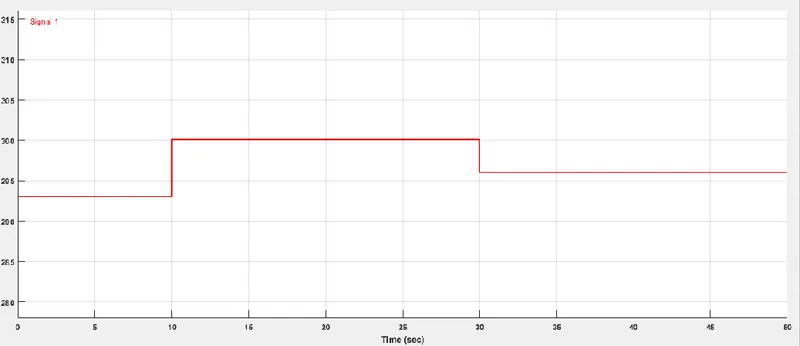
- Temperature source: 20 °C from 0 to 10 seconds, 27 °C from 10 to 30 seconds, 23 °C from 30 to 50 seconds.
- Fan conditions: ON if the temperature above 25 °C, OFF otherwise
SOLUTION :
- The objective is to sense the temperature using thermistor and turn off the fan as per below conditions.
- The conditions are :
From 0 to 10 sec the temperature is 20 °C in kelvin 293 K
From 10 to 30 sec the temperature is 27 °C in kelvin 300 K
From 30 to 50 sec the temperature is 23 °C in kelvin 296 K
- The temperature is given in the form of degree celsius. so, it is converted into Kelvin.
- 1 Kelvin = 273 °C ( Formula of conversion )
- In signal builder it is given in the form of kelvin to generate the signal with respect to time as shown in the below figure.
Signal given in Signal Builder
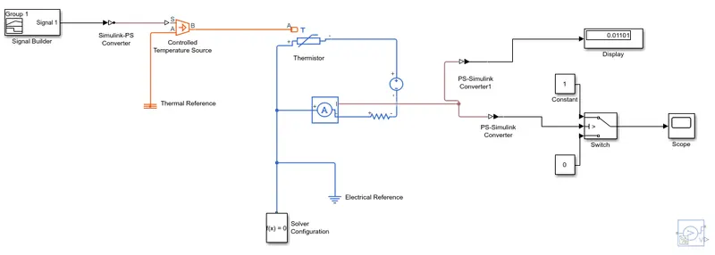
Diagram simulated in simulink
- Form the given condition the Fan is switched ON if the temperature above 25 °C and should be switched OFF other than the condition.
- The blocks should be taken according to the requirements for the given conditions, then the blocks need to be conected as shown in the above figure.
- Here the signal is passed through controlled temperature source to thermistor, then current sensor is used which is connected parllel to the thermistor.
- Then the signal is further connectec to Dispaly and scope using two Physical to simulink convertors.
- First the data is passed from current sensor to display through the PS-Simulink convertor and the threshold value that need to be given to switch is shown in the display.
- After the data is given to switch as per the condition if the threshold value is above 1 then the fan will be in ON condition else the fan will be in OFF condition.
Result :
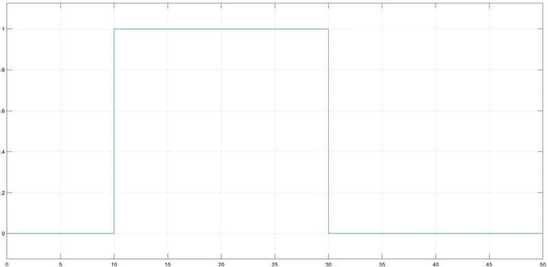
Simulation results of FAN as per conditions
- Now the above mentione figure represents the simulation results of fan for required conditions.
- If we observe the graph it is clear that in between the timeline of 0 - 50 sec as per the condition the temperature is above 25 °C from 10 - 30 sec and the graph shows its response raising from 0 to 1 sating that the fan is in ON condition.
- Rest in all other timing the fan is in OFF condition.