Week -2
- Make a Simulink model of Doorbell using a solenoid block with the following details:
In the above arrangement, when the switch is closed the electromagnet receives electrical power from the battery and pulls the metal arm to hit the bell producing sound.
Create a situation where the switch is closed for 2 seconds and then released. Observe the physical movement of the plunger.
Assume remaining parameters.
Objective:
To Develop a Simulink model of doorbell using Solenoid block.
Main Blocks used:
Battery
Solenoid
Switch
Motion Sensor
Pulse Generator
Scope
The concept behind the model:
Solenoid:The Solenoid block represents the electrical characteristics and generated force for the solenoid in the following figure:
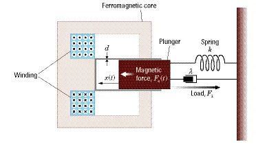
- The above block shows that it is a doorbell and whenever the plunger is applied with force, then the bell rings.
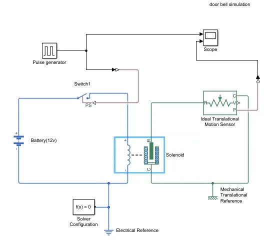
- To perform this, an Electrical switch is arranged to perform the On and Off of the electrical signal.
- The battery is connected to the electrical switch to give the electrical signals to the solenoid.
- Switch On and OFF options are generated with the help of a pulse generator.
- The motion of the solenoid is sensed by the translational motion sensor and the same is replicating in the scope.
- In the model, the Electrical reference and Mechanical references are given as per the requirement for better grounding.
- Default Solver configuration is applied in the appropriate location of the model.
- change of physical system to Simulink system and vice-versa applied where the change of system required.
Results:
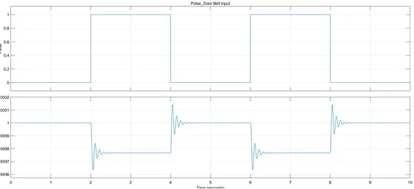
Results of the doorbell simulation are as shown above.
The first graph tells the pulse generation input to the doorbell.
The second graph shows that how the pulsation is varied whenever the changes applied.
The oscillations shown are the result of the damping value in the solenoid.
whenever there is a change in pulse, the bell is making the noise and the same is shown in the form of vibration or oscillations.
Note:
Change in the voltage, change in damping of the solenoid, variations in pulse generators varies the output in the scope.
2. Use a thermistor to sense the temperature of a heater & turn on or turn off the fan as per below conditions:
Temperature source: 20 °C from 0 to 10 seconds, 27 °C from 10 to 30 seconds, 23 °C from 30 to 50 seconds
Fan conditions: ON if the temperature above 25 °C, OFF otherwise
Objective:
To develop a model for operating Fan turn on and off based on the temperature of the heater with the help of a thermistor.
Conditions given are: Temperature is 20 °C from 0 to 10 seconds,
27 °C from 10 to 30 seconds,
23 °C from 30 to 50 seconds
Fan conditions: When the temperature is above 25 °C, Fan is ON. OFF otherwise
Main Blocks used:
Battery
Thermistor
Controlled temperature sensor
voltage sensor
Signal builder
Switch
controlled voltage source
DC Motor
Rotational Motion Sensor
Motion Sensor
Scope
Simulink Model:
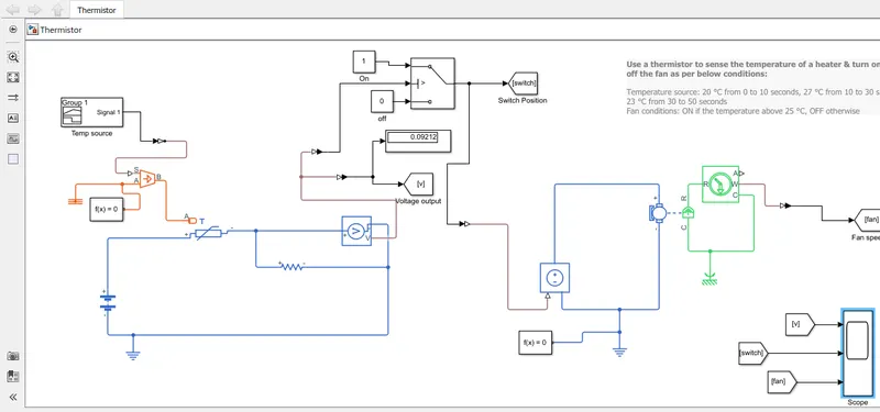
Model:
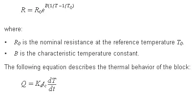
The Thermistor block represents an NTC thermistor using the B-parameter equation. The resistance at temperature T is
- A thermistor is connected with the temperature sensor block to sense the temperature input from the signal builder block.
- the voltage sensor is connected to the thermistor which senses the voltage output from the thermistor.
- The voltage sensor is connected to the switch which works with a logic that if the temperature is above 25 degrees, then the switch is on, and otherwise switch is Off.
- A DC motor is connected to the switch through a controlled voltage source which operates with the signal of the Switch.
- DC motor is connected to the Rotational Motion sensor, which helps the model to identify the rotation of the DC motor and in turn the operation of Fan.
- Scopes are arranged to view the signals from the Thermister, Switch, and the functioning of the DC motor through the Rotation sensor which replicating the operation of the Fan.
- In the model, the Electrical reference and Mechanical references are given as per the requirement for better grounding.
- Default Solver configuration is applied in the appropriate location of the model.
- change of physical system to Simulink system and vice-versa applied where the change of system required.
Results:
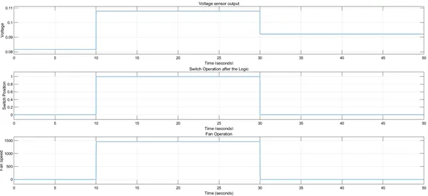
- Above are the observations made for the operation of the Voltage sensor output, Switch and Fan operation. As per the requirement given the signal input is varying at 10 sec, and 30 seconds.
- Temperatures are considered with signals at 0 to 10 seconds as 20 degrees, 10 to 30 seconds as 27 degrees, and 30 to 50 as 23 degrees.
- FAn operation is required when the temperature is above 25 degrees which are happening between 10 to 30 seconds. So the switch is operating in this zone at scope 2.
- In scope 3, at 10 to 30 seconds, fan speed is observed as 1500 rpm in this time zone.
- Hence it is concluded that the above model is operating with the given requirements.