Week -2
Assignment_1
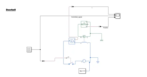
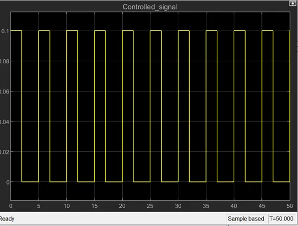
Given below is the pulse signal which is passed through Single Pole Single Throw(SPST) switch to control the switching. One pulse is for 2 sec and has 0.1 amplitude and after the pulse there is a 3 sec gap . This pattern is repeated till 50 sec. Threshold put in the SPST switch is 0,so whenever the signal is above 0 the switch will be closed else it will get opened.
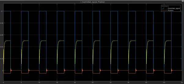
I have used a 10V DC Voltage source so whenever the switch is closed the current will pass through the solenoid (an electromagnet) and will generate magnetic fields. Due to these magnetic fields ,the translational motion sensor attached to the other part of the solenoid will show some position change in negative direction as a positive current from the electrical + to - ports results in a negative force (i.e. pulling force) acting from the mechanical C to R ports , whenever the switch is closed and the position change will be zero once the switch is opened. This thesis is used in the Doorbell i.e. whenever the solenoid gets energized it will pull the permanent opposite magnet towards itself which will ultimately hit the bell .So as per our switching mechanism ,bell will ring for 2 sec and then it will be silent for 3 sec and this will continue for 10 times till 50 sec.
Given below is the plot of the Current flowing in the electrical part, controlled signal to control the SPST switch and finally the position change sensed by the sensor. Whenever the controlled signal is above 0 ,there is position change in negative direction due to pulling force.
Link:https://drive.google.com/drive/folders/1cLn6imKqHd0gfL10r5s0gEhkhB3yYR-P?usp=sharing
Assignment_2
I have taken a signal builder to create a waveform as per the scenario provided in the question i.e. 20 degree celsius from 0-10 sec ,27 degree celsius from 10-30 sec & 23 degree celsius from 30-50 sec.
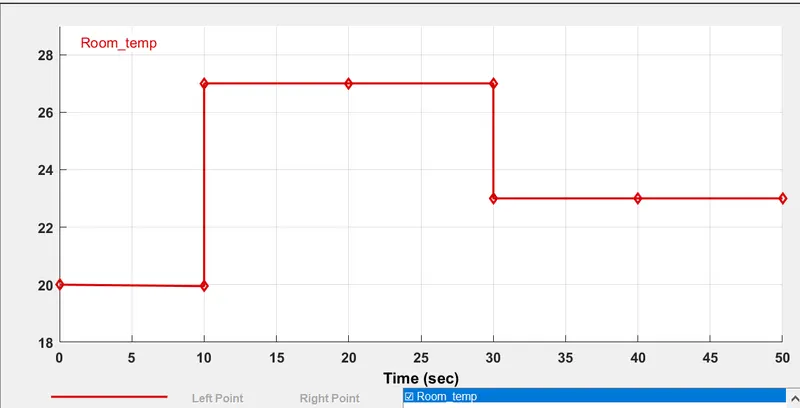
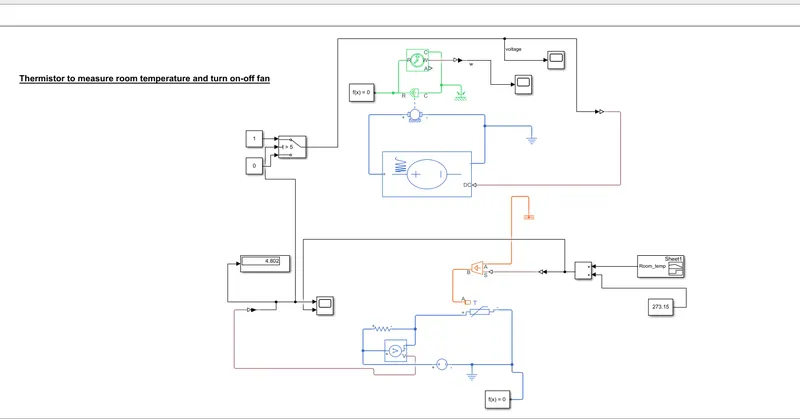
The waveform is in celsius so to convert it into Kelvin scale I have added the entire waveform with a constant 273.15 K. Now,the output of the sum block is passed through the controlled temperature source & the heat is sensed by the thermister from the heater. Due to this variation in temperature ,the resistance of the thermistor will also vary. The thermister present in the model is NPT i.e. Negative Temperature Coefficient which means the resistance of the thermister will decrease when the temperature sensed by it increases.Now,if the resistance across the thermister will increase or decrease,this will lead to Voltage variation across the nearby resistor .I have taken help of a scope to read the voltage across this nearby resistor and I found out the following :
when,
--temperature sensed by the thermistor is 20 degree celsius(293.15K) , Voltage across the resistor is 4.5V
--temperature sensed by the thermister is 27 degree celsius(300.15K) ,Voltage across the resistor is 5.2V
--temperature sensed by the thermister is 23 degree celsius(296.15K) ,Voltage across the resistor is
4.8V
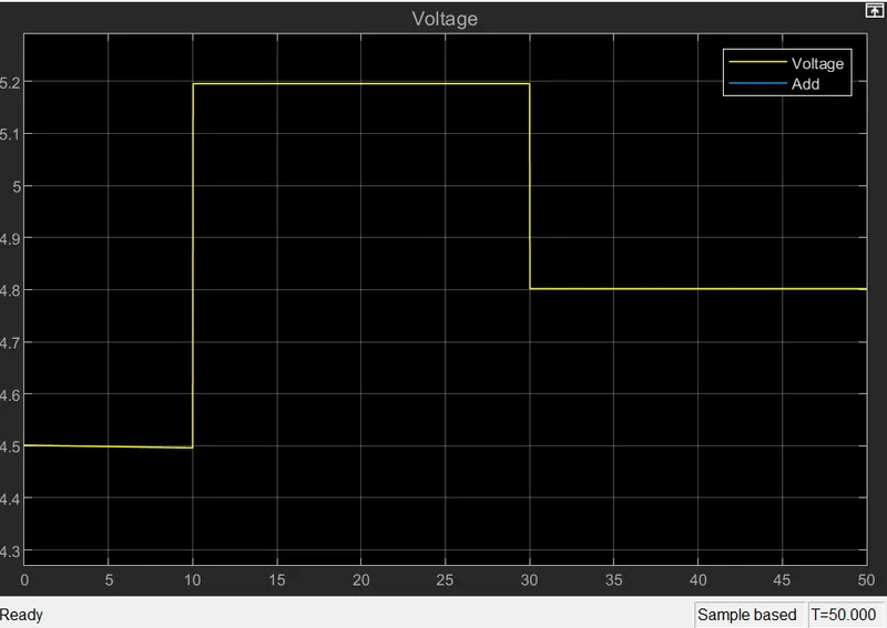
Now, as per the scenario provided in the question i.e. whenever room temerature is greater than 25 degree celsius the fan will be on and it will off otherwise, I have taken a switch block whose function is to pass 1 whenever temperature is above 25 degree celsius else it will pass 0.So as per the voltage plot ,one can find out that for 25 degree celsius the reference voltage is 4.8V hence whenever voltage is above 4.8 V ,the switch block will pass 1 else it will pass 0.
The output of the switch block is a waveform consisting of 1 & 0.Now,this waveform will pass through the programmable voltage source .This block will act as a dc voltage source whenever the switch block passes 1 and it will not provide voltage when the switch block passes 0. The voltage is provided in a programmed way across the dc motor which will make the ideal rotational motion sensor sense torque through port R which will be converted to the angular velocity when room temperature is above 25 degree celsius(I have captured in the scope) .There will be no torque when the switch passes 0. This torque is basically the driving factor which will run the fan.
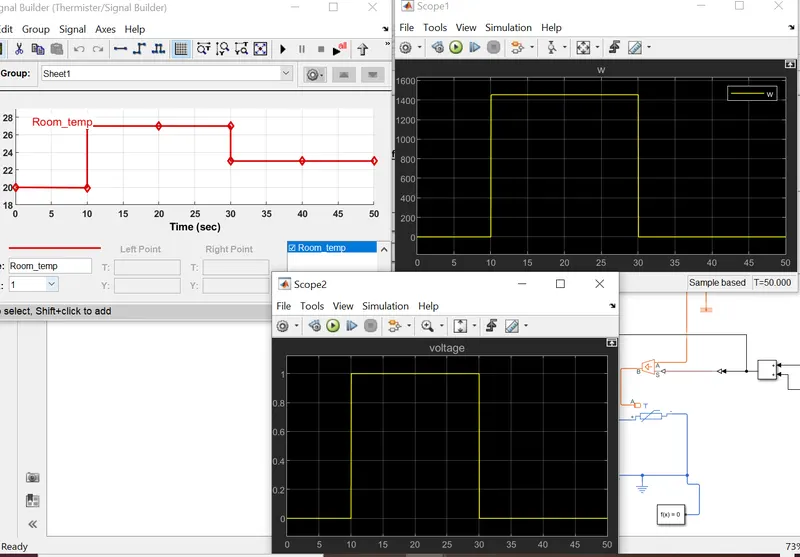
Note :All signals are plotted separately because of the remarkable gap across their ranges.
We can see that we are not getting any angular velocity for 0-10 sec or 30-50 sec as temperature in this time window is less than 25 degree celsius.We are only getting angular velocity for 10-30 sec as temperature is greater than 25 degree celsius.
Link : https://drive.google.com/file/d/1-YqmwslJ-xejKi_VAFJoER5Z9WwH6Znq/view?usp=sharing