Week -2
TASK 1
AIM:
- To make a simulink model of door bell using solenoid block.
OBJECTIVE:
- Create a situation where the switch is closed for 2 seconds and then released.Observe the physical movement of the plunger.
THEORY:
A solenoid is simply a specially designed electromagnet. A solenoid usually consists of a coil and a movable iron core called the armature. Here's how it works. When current flows a magnetic field is set up around the wire.If we make a coil of many turns of wire, this magnetic field becomes many times stronger, flowing around the coil and through its center in a doughnut shape. When the coil of the solenoid is energized with current, the core moves to increase the flux linkage by closing the air gap between the cores. The movable core is usally spring-loaded to allow the core to retract when the current is switched off. The force generated is approximately proportional to the square of the current and inversely proportional to the square of the length of the air gap.
Solenoids are inexpensive, and their use is primarily limited to on-off applications such as latching, locking, and triggering. They are frequently used in home appliances (e.g. washing machine valves), office equipment (e.g. copy machines), automobiles (e.g. door latches,doorbell and the starter solenoid), pinball mahines (e.g., plungers and bumpers), and factory automation.
Governing Diagram:
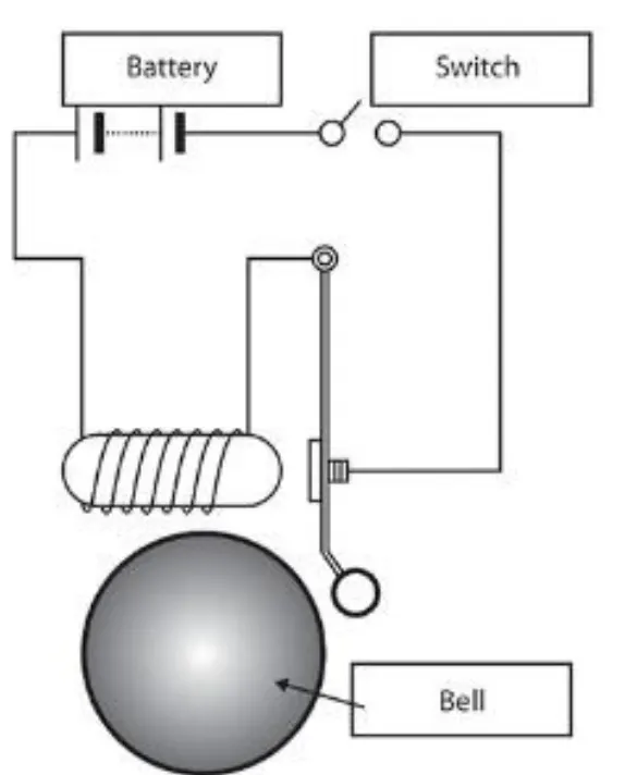
BLOCK DIAGRAM:
Here is the image of block diagram.
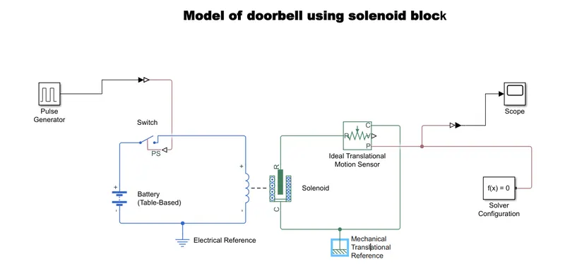
Explanation:
- From the governing diagram we need major components like solenoid,battery,switch etc..
- First we have taken the solenoid block to represent the solenoid in the model.
- To represent the switch we used switch block and in the same way to represent battery we used battery block. These blocks are taken from library browser.
- Switch block is placed in between the battery block and solenoid block.
- A positive terminal of the battery block is connected to the switch one end and another end is connected to the positive terminal of the solenoid.we used a physical signal through ‘PS’ port in the ‘Switch Block’. The provided physical signal should be greater than the threshold of the switch, for switch being closed, or else it will open.
- The negative terminal of the battery is given to the negarive terminal of the solenoid, The the whole set up is connected to a Electrical reference block. (Note: It should be connected to the negative terminal of the block only).
- Now coming to the solenoid block there are two variables called 'R' and 'C'. These variables denotes like 'R' is plunger and 'C' is fixed point.
- Now we have insert a block called Ideal translation motion sensor which sense the position of Solenoid block and give output.
- Now 'R' of a solenoid block is connected to the 'R' of a Ideal translational motion sensor.
- The Ideal Translation motion sensor output contains two variables called 'P'.'V'. 'P' is position of plunger and 'V' is velocity of plunger.
- Now 'C' of the solenoid part is connected to the 'C' of the Ideal translation motion sensor.This is connected to a Mechanical translational reference.
- Now port 'P' is connected to a PS-Simulink converter and this converter is connected to scope block which gives the plots as output.
- To define a solution we used solver configuration block, This block is connected at the connection of port 'P' and PS-simulink converter.
- We have to add a pulse generator block, it defines the computational technique.It generates a continuous pulse. This block is added to a physical signal of operating switch.
- Save the program and run it.
Here is the image of pulse generator
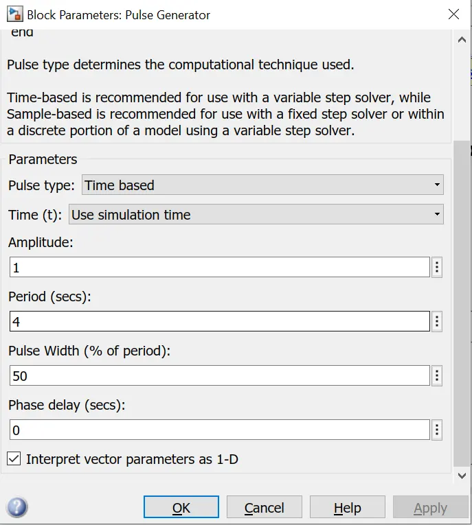
- From the above Figure we can observe that we have taken we have given period value as ‘4’, pulse width as ‘50’, phase delay as ‘2’ and amplitude by default is ‘1’ we have not changed it. This means that initially the pulse will be zero, since we have given phase delay of ‘2’ so till 2 sec the pulse will be zero and at 2 secs the pulse will start from zero to 1 since we have given amplitude as ‘1’ and then now the pulse width will half of period ,so for the next two seconds the pulse will be at amplitude ‘1’ only, then it will again come down to zero at 4th second and then it will at zero for next 2 secs thus completing the period of 4 seconds.
OUTPUT:
Here is the image shows the graph
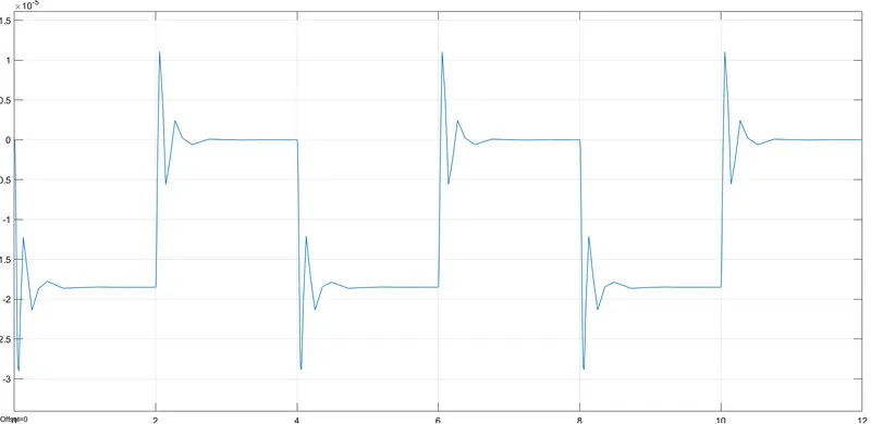
- By double click on the scope block we will get this graph.
- Here X-axis represents time and Y-axis represents plunger position.
CONCLUSION:
- The creation of Doorbell is done using Simulink and observed the ouput results generated from the motion sensor, the result is satisfactory.
TASK 2:
AIM:
- To make a simulink model by using a thermistor to sense the temperature of a heater & turn on or turn off.
OBJECTIVE:
- Temperature source is to be 20 °C from 0 to 10 seconds and 27 °C from 10 to 30 seconds and 23 °C from 30 to 50 seconds.Fan conditions is to be ON if the temperature above 25 °C, OFF otherwise.
THEORY:
A thermistor is a type of resistor whose resistance strongly depends on temperature. The word thermistor is a combination of words “thermal” and “resistor”. A thermistor is a temperature-sensing element composed of sintered semiconductor material and sometimes mixture of metallic oxides such as Mn, Ni, Co, Cu and Fe, which exhibits a large change in resistance proportional to a small change in temperature. Pure metals have positive temperature coefficient of resistance, alloys have nearly equal zero temperature coefficient of resistance and semi conductors have negative temperature coefficient of resistance.
Thermistors can be classified into two types:
- Positive temperature coefficient (PTC) thermistor:-resistance increase with increase in temperature.
- Negative temperature coefficient (NTC) thermistor:-resistance decrease with increase in temperature.
The thermistor exhibits a highly non-linear characteristic of resistance vs. temperature.
BLOCK DIAGRAM:
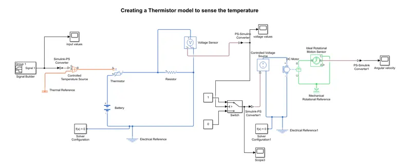
Explanation:
- Firstly we inserted a Signal Builder and it is used to give our inputs of Temperature with time and add a scope to plot the input values.
- And we connected a Controlled Temperature Source to a signal builder with the help of simulink-PS converter. This Controlled Temperature Source represents an ideal energy source in a thermal network that can maintain a controlled temperature difference regardless of the heat flow rate.
- We added a thermistor, it represents an NTC thermistor. A resistor is added to the thermistor and another end is connected to the battery.
- We connected a Voltage sensor parallel to the resistor. This voltage sensor converts voltage measured between any electrical connections into a physical signal proportional to the voltage.
- Add thermal reference to the controlled temperature source and elecrtical reference to the battery setup.
- Now insert a switch box,This block pass through input 1 when input 2 satisfies the selected criterion; otherwise, pass through input 3. We attached a constants to switch representing that if '1' is there flow of current is possible, if '0', there is no current.
- In this case we need the fan to get ON and OFF at different temperatures. So, to provide temperature, we have used ‘Controlled Temperature Source Block’ which only gives a specified temperature as output even though heat flow is more.
- We attached a DC motor to controlled temperature source it represents the electrical and torque characteristics of a DC motor.
- Now we connected the DC motor to Ideal rotational motion sensor to detect wether there is any rotational motion in the DC Motor during the simulation.
- Finally we connected this to the scope by using PS-Simulink convertor.
- This DC motor setup is connected to a mechanical rotational reference.
PARAMETERS:
Input: The temperature input is given using the signal builder block.
Output: The temperature values are converted in to Voltage values and plotted. The voltage values are later used as input of DC motor block and angular velocities are plotted.
INPUT:
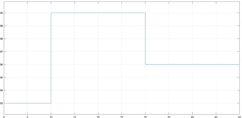
- Here X-axis represents Time in (sec) and Y-axis represents Temperature in (kelvin)
-
from 0 to 10 sec - 293K
-
from 10 to 30 sec - 300K
-
from 30 to 50 sec - 296K
OUTPUT:
1) Here is the image of voltage values w.r.t time
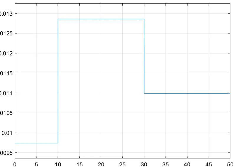
- You can see that we converted the temperature at each 'sec' into its corresponding 'voltage' value
- If we observe the graph, we notice that from time 0 to 10 seconds when temperature is 293K, voltage is between 0.0095 and 0.01 and from time 10 to 30 seconds when temperature is 300K, voltage is between 0.0125 and 0.013 and from time 30 to 50 seconds when temperature is 296K, voltage is nearly 0.011.
- As mentioned in the objective fan should be ON when temperature is more than 25 degree Celsius, from the above graph when voltage is more than 0.011 the fan should ON and when voltage is below 0.011, fan should be OFF.
- To set the threshold value of ‘Switch Block’, we have to double click on the ‘Switch Block’ and then we can change the value of threshold. Since we want switch to be ON only when temperature is 300K so the threshold is given as 0.011. So when voltage gets more than 0.011 the switch will give value 1 as output which means fan will be ON and when voltage gets less than 0.011 the switch will give value 0 as output which means fan will be off.
2) Here is the graph of switch block that represents ON & OFF by using constant 1 & 0
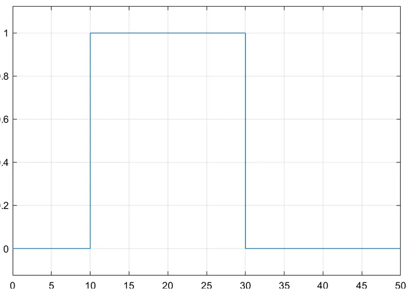
- By observing the graph we can clearly see that when temperature is above 298K the fan is ON and at remaining temperatures the fan is OFF.
3) Here is the graph of Angular velocity w.r.t time
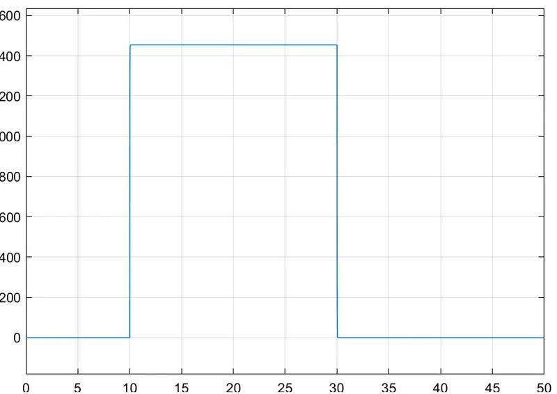 .
.
- We can observe that there is a change in angular velocity from 10sec to 30sec during the simulation. It shows that when the temperature value crosses above 298K, the motor gets started.
CONCLUSION:
- The Creation of Thermistor model to measure the Temperature is done using the Simulink model and the results are satisfactory.