Week 2.1 - Air standard Cycle
AIM:
- To create a PV diagram of air standard cycle.
- To get the output of the thermal efficiency of the engine.
AIR STANDARD CYCLE:
The Air-standard cycle is also known as Otto cycle which approximates the processes in petrol or diesel engines. It is based on constant volume heat addition (combustion) and heat rejection processes, and isentropic compression and expansion.
The four stroke Otto cycle is made up of four reversible process
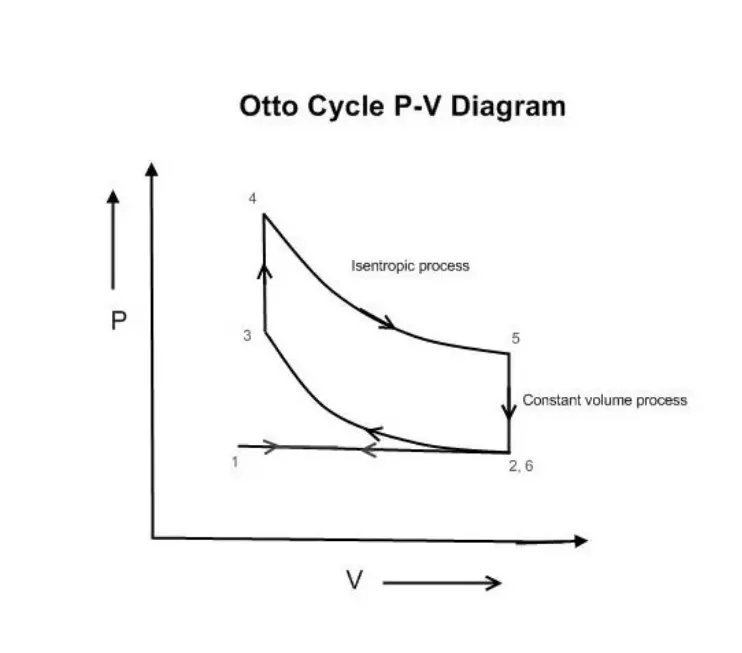
Process 1-2 :Isentropic Compression
Process 2-3 :Constant volume heat addition
Process 3-4 :Isentropic Expansion
Process 4-1 :Constant volume heat rejection
PROGRAM:
FUNCTIONAL PROGRAM TO CALCULATE SWEPT,CLEARANCE AND COMBUSTION VOLUME
function [v]=piston_kinematics(bore,stroke,con_rod,cr,starting_crank,ending_crank)

a=stroke/2;
R=con_rod/a;
vs=pi/4*stroke*bore^2;
vc=vs/(cr-1);
theta=linspace(starting_crank,ending_crank,100);
term1=0.5*(cr-1);
term2=R+1-cosd(theta);
term3=(R^2-sind(theta).^2).^0.5;

v=(1+term1*(term2-term3)).*vc;

end
EXPLANATION:
In this program a Function is created to calculate swept volume and clearance volume.
In which basically we have created a templelate to calculate the volume of clearance,swept,and combustion by assiging the formula inside the code using function and getting the output value based on the input value assigned.
PROGRAM TO GET P-V DIAGRAM AND THERMAL EFFECIENCY FOR AIR STANDARD CYCLE
close all
clear all
clc

gamma=1.4;

%State varialbles
t1=500;
p1=101325;
t3=2300;

%Engine  geomentric parameters
bore=0.1;
stroke=0.1;
con_rod=0.15;
cr=12;

%Calcualte the Swept volume and cleareance volume
v_swept=(pi/4)*stroke*bore^2;
v_cleareance=v_swept/(cr-1);

v1=v_swept + v_cleareance;
v2=v_cleareance;

%State variable at state point 2
%(p2*v2)^gamma=(p1*v1)^gamma
%p2=p1*((v1/v2)^gamma)
p2=p1*(cr^gamma);
%p1v1/t1=p2v2/t2
t2=p2*v2*t1/(p1*v1);

constant_c=p1*v1^gamma;
v_compression=piston_kinematics(bore,stroke,con_rod,cr,180,0);

%p_compression*v_compression^gamma=constant_c
p_compression=constant_c./v_compression.^gamma;

%State variable at state point 3
v3=v2;
%p3v3/t3=p2v2/t2
%p3=p2t3v2/t2v3
p3=(p2*t3)/t2;


constant_c=p3*v3^gamma;
v_expansion=piston_kinematics(bore,stroke,con_rod,cr,0,180);

%p_expansion*v_expansion^gamma=constant_c
p_expansion=constant_c./v_expansion.^gamma;
%State variable at state point 4
v4=v1;
%(p3*v3)^gamma=(p4*v4)^gamma
%p4=p3*((v3/v4)^gamma)
p4=p3*((v3/v4)^gamma);

thermal_effeciency=(1-(1/cr^(gamma-1)))*100;

%Plotting
figure(1)
hold on
plot(v1,p1,'*','color','r')
plot(v_compression,p_compression)
plot(v2,p2,'*','color','r')
plot(v3,p3,'*','color','r')
plot(v_expansion,p_expansion)
plot(v4,p4,'*','color','r')
EXPLANATION:
1. Assigning an input for gamma and State varialbles
gamma=1.4;
t1=500;
p1=101325;
t3=2300;
2.And Assigning the Engine geomentric parameters to calculate the volume
bore=0.1;
stroke=0.1;
con_rod=0.15;
cr=12;
3.Now formula is inserted to calculate the swept volume,clearance volume,v1 and v2
v_swept=(pi/4)*stroke*bore^2;
v_cleareance=v_swept/(cr-1);
v1=v_swept + v_cleareance;
v2=v_cleareance;
4. Now State variable at state point 2 which the value is (p2*v2)^gamma=(p1*v1)^gamma to get the p2 & t2 value we assigned
%p2=p1*((v1/v2)^gamma)
p2=p1*(cr^gamma);
%p1v1/t1=p2v2/t2
t2=p2*v2*t1/(p1*v1);
5. Now functions is used to calculate compression volume value
constant_c=p1*v1^gamma;
v_compression=piston_kinematics(bore,stroke,con_rod,cr,180,0);
%p_compression*v_compression^gamma=constant_c
p_compression=constant_c./v_compression.^gamma;
6. Now State variable at state point 3
v3=v2;
%p3v3/t3=p2v2/t2
%p3=p2t3v2/t2v3
p3=(p2*t3)/t2;
5. Again functions is used to calculate expanison volume value
constant_c=p3*v3^gamma;
v_expansion=piston_kinematics(bore,stroke,con_rod,cr,0,180);
%p_expansion*v_expansion^gamma=constant_c
p_expansion=constant_c./v_expansion.^gamma;
6.Now State variable at state point 4
v4=v1;
%(p3*v3)^gamma=(p4*v4)^gamma
%p4=p3*((v3/v4)^gamma)
p4=p3*((v3/v4)^gamma);
7. Thermal effeciency formula is used to calulate the effeciency value
thermal_effeciency=(1-(1/cr^(gamma-1)))*100;
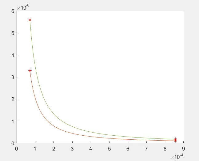
8. Plotting the graph to get the P-V diagram of air standard cycle.
figure(1)
hold on
plot(v1,p1,'*','color','r')
plot(v_compression,p_compression)
plot(v2,p2,'*','color','r')
plot(v3,p3,'*','color','r')
plot(v_expansion,p_expansion)
plot(v4,p4,'*','color','r')
ERRORS FACED:
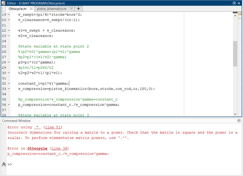
Error 1: Missed '.' to calculate the elementwise matrix power.Instead of v_compression.^gamma I typed v_compression^gamma
Action: The error was corrected by adding .(dot) before the power value to calculate the matrix
OUTPUT:
1. PV diagram of air standard cycle:
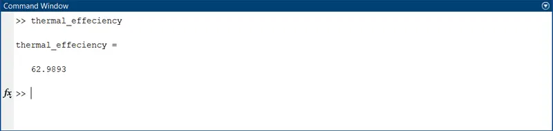
2.To get the output of the thermal efficiency of the engine.