Week 14 challenge
Butterfly valve
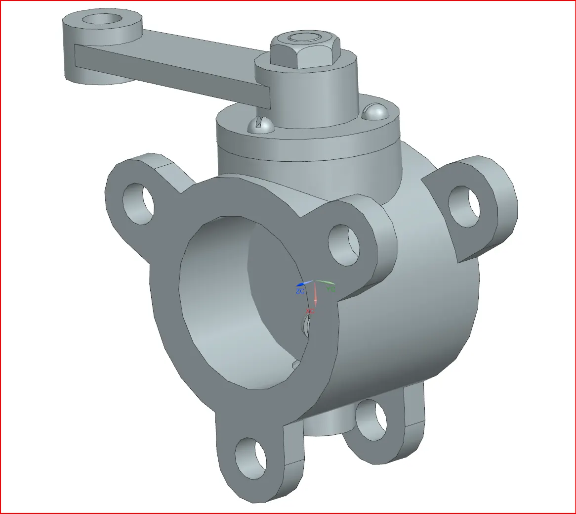
Butterfly valve is used to regulate flow, pressure of the fluid or gases. It is called butterfly because the disc in the butterfly valve looks like butterfly wings
WORKING OF BUTTERFLY VALVE
The main part is the disc which rotates around the central axis. When you turn around the valve handle the disc rotates when the disc is parallel to the flow then the valve is open and fluid can flow easily and when the disc is flat then the flow will not be there.
Butterfly valve has lots of Advantages like they are lightweight easy to open and close, affordable. Application Also they are commonly found in water system chemical plant, HVAC systems where they help control the flow of fluids and gases.
In this report Modelling and drafting of each components with consideration of GD&T and its applications. An assembly and exploded view is also created to clearly display each parts. The following are the parts of the butterfly valve :-
1.BODY VALVE
The material selection while designing that depends on applications, fluid type, pressure and also on the environmental conditions as follows
a. CAST IRON :- Frequently used for low pressure also used for water and HVAC also it is durable and affordable too
b. DUCTILE IRON:- When in comes with high pressure applications then Body valve should have a material of ductile iron since it is more flexible than cast iron.
c. STAINLESS STEEL:- This is suitable where we need corrosive free output flow like in food industry, pharmaceutical industry. It is ideal for corrosive environments.
d. CARBON STEEL:- Suitable for high pressure and high temperature , used in application of gas, oil and industrial systems.
e. BRONZE:- Often used for marine applications because it resist corrosion from sea water.
f. PVC or plastic:- Often used for low pressure applications that don't react with plastic.
Also while designing the body valve following consideration should be kept in mind like:-
- MATERIAL SELECTION as discussed earlier
- FLOW Capacity, flow rate also the valve should allow minimum turbulence
- PRESSURE AND TEMPERATURE RATINGS
- SEALABILITY AND LEAKAGE it must be prevent leak and also choose seal material appropriate so that it will wear minimum
- Ease of operation
- STRENGTH AND DURABILITY it should be shock and vibration proof for that structure should withstand that much amount of pressure while operation.
- MANUFACTURING methods should be chosen in such a way so that less cost and minimize complexity
- SAFETY AND ENVIRONMENT CONDITION design in consider with humidity exposure to chemical , UV light .
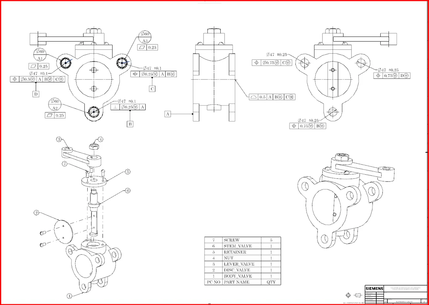
The drawing of BODY VALVE is along with the other components as shown below:-
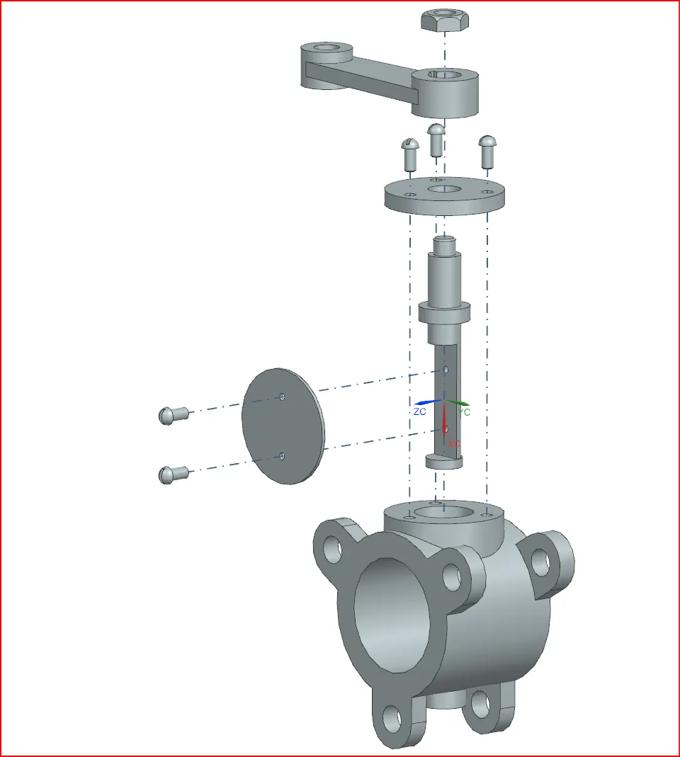
Also the exploded view of butterfly valve assembly as shown below
2. Disk Valve
On turning the valve handle the disk rotates and by the help of the orientation of the disk the flow can be regulated
The material selection while designing the disk depends on the applications, type of fluid flow, pressure. Here are commonly used material for butterfly valve disk as follows:-
a. STAINLESS STEEL:- Excellent corrosive resistance , suitable for high temperature and high pressure environment
b. DUCTILE IRON :- good for low to medium pressure best suited for water treatment plant, HVAC
c. ALUMINIUM BRONZE :-
d. INCONEL:- Superior oxidation resistance best suited for nuclear reactor, chemical plant
e. NYLON COATED OR RUBBER LINED DISK :- coating provide resistance to specific chemical or abrasive fluid, best suited for slurry handling , waste water
While design the disk valve following consideration should be kept in mind like:-
- DISK PROFILE A streamlined design reduces drag , pressure drop and turbulence which can improve efficiency
- SEALING Design for tight shut off and compatibility with seat material
- DYNAMIC AND FATIGUE CONSIDERATION For applications involving frequent open- close fatigue resistance is important and for that material selection & disk profile become more critical to prevent fatigue failure also when the flow is very high or having high pressure the disk may experience vibration or flutter which can cause mechanical wear and fatigue
- STRENGTH Analyze strength under maximum pressure.
The drawing of disk valve is shown below
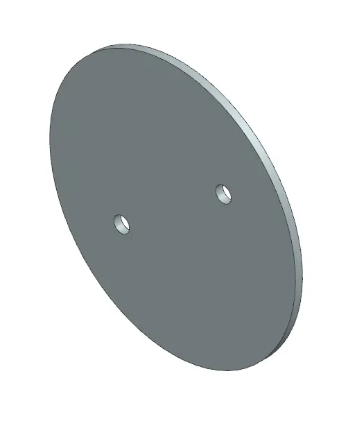
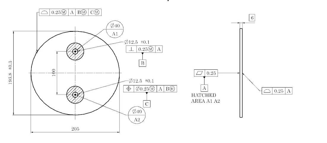
In the drawing of disc for valve only hole of dia 12.5 mm havid cd is 100 is important and for that we give datum target to it, also on giving Flatness of 0.25 AREA A1 A2 as Datum A & Since profile is also important because it will be rest on the lever so we gave 0.25 profile of surface with respect to Datum A
Also given perpendicular tolerance of 0.25 having mmc condition with respect to DATUM A & that FOS is denoted by another datum called B DATUM AS SHOWN ABOVE
Also giving position tolerance of 0.25 MMC W.R.T datum A AND DATUM B MMC to another hole and make it as a datum C.As shown above.
3 LEVER VALVE
The purpose of lever is to control the disc orientation in this lever the one face is butt on the retainer and that retainer is butt on the stem there is a key slot is given on the lever valve and on the stem as shown below
the shaft/stem is tightened with lever by the help of HEX NUT.
Here are the few design consideration for lever :-
- 1. Torque and force required:-The lever must generate sufficient torque to open and close the valve smoothly, and the required torque depends upon the valve size, pressure and types of fluid also the design should minimize the force need to turn the valve
- 2.Lever length :- The larger the lever length the less will be the torque required but it create problem in confined space.
- 3.Material selection :- The material should be selected in such a way to handle or strong enough to handle maximum torque during valve operation. Common materials are stainless steel,
- 4. Locking Mechanism:- Many butterfly valves require a locking mechanism to hold the valve in a closed, fixed, partially open position to avoid any unnecessary movement.
- 5.Indicator for valve position : To show the valve position (open, closed, or throttled )
- 6. Fatigue and durability:- The valve are subjected to frequently open and close in some applications. So the lever should be design to ensure that the material are resistant to fatigue from repeated cyclic application.
The drawing of lever of valve is shown below
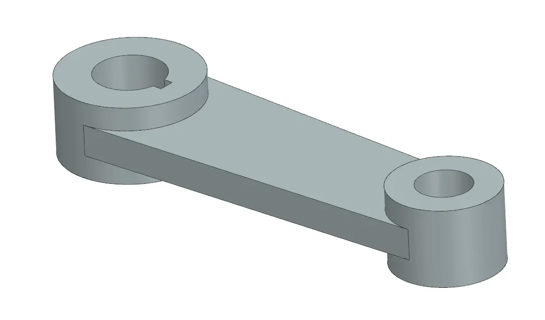
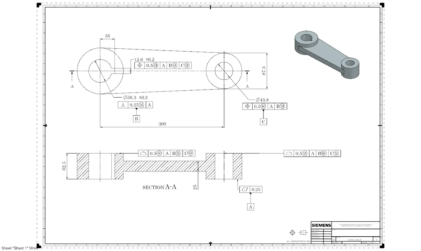
The surface which is going to but on the retainer is giving a flatness of 0.25 and that surface is our datum A as shown in drawing. The slot of dia 56.3 is very much important so we have give a perpendicularity of 0.25 of maximum material condition w.r.t datum A and that feature of size is given as a B datum.
Another hole of dia 43.8 is also important and for that we gave position tolerance of 0.5 MMC w.r.t A & B datum as shown and make this feature of size as Datum C
all other surface is given a profile of surface tolerance of 0.5 MMC w.r.t other three datums as shown.
4. Retainer
The function of retainer to hold the other components in a place under operation conditions such as high pressure and temperature while maintaining proper alignment.
Here are the few design consideration to design retainer :-
- Material selection:-The retainer must be strong enough to withstand operational fluid pressure, stresses, mechanical force during operation. Also material should be selected in such a way to resist corrosion, to prevent failure or degradation over time.For corossion resistance coating or material like ss316 are ideal.
- Retainer Shape and profile :-It should have compact design and smooth surface to avoid any restriction/wear between components.
- Leak Proof:- It should be compatible with gaskets or O ring to improve sealing also it should be ensure the tight fit between the components and retainer to prevent leakage
The drawing of retainer of valve as shown :-
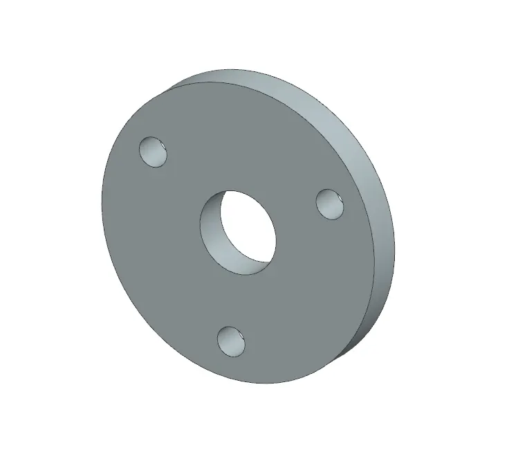
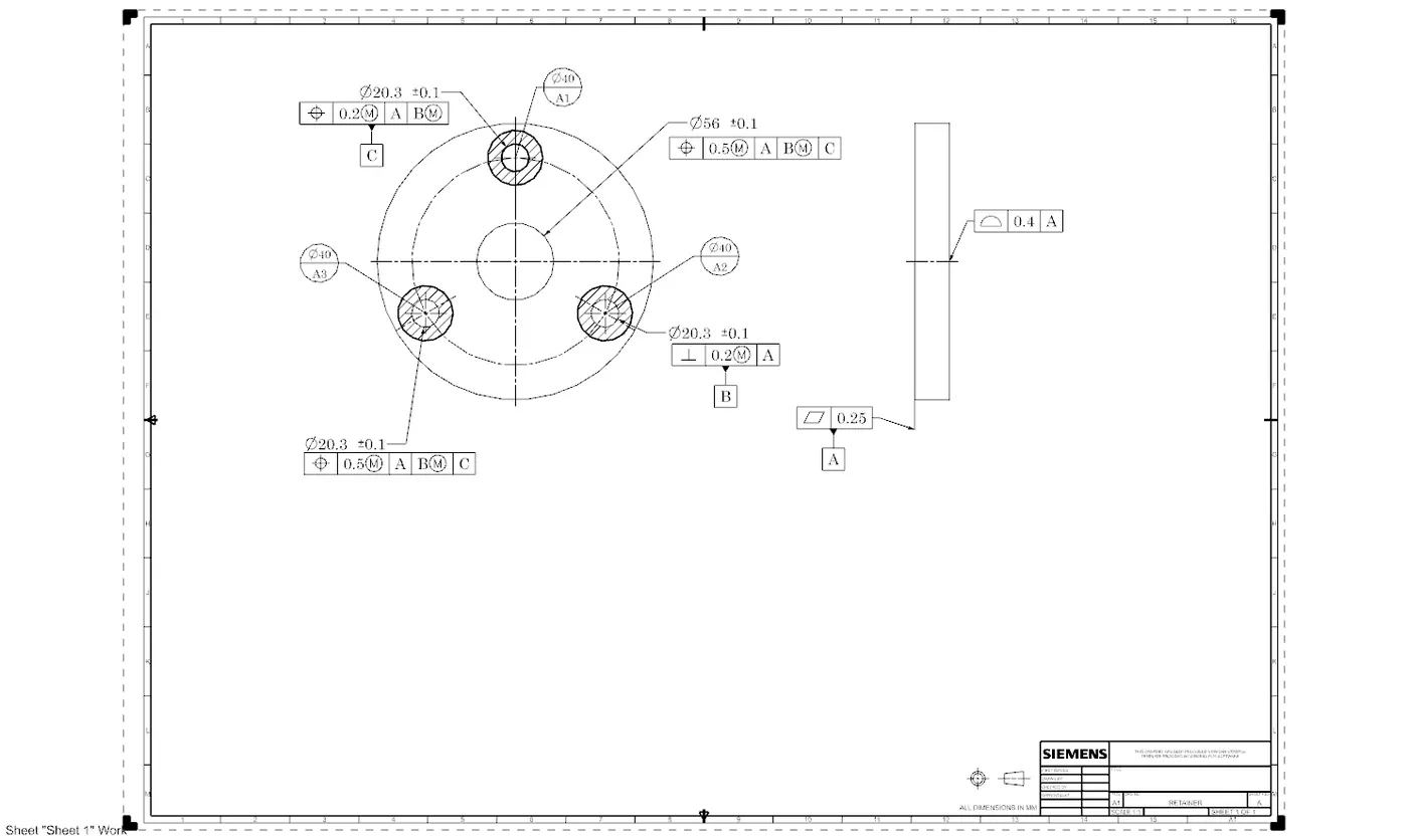
In this drawing of retainer the bottom surface is important so maintaining 0.25 of flatness and make it as a Datum A as shown and on the other surface given profile of 0.4 w.r.t Datum A.
the hole of 20.3 is also important so instead of making flatness to the hole surface A we make datum target of diameter 40 mm namely A1, A2, A3 so instead of maintaining flatness of 0.25 of bottom surface maintain only dia of 40 mm and combining Datum targets A1, A2, A3 as a datum A as shown now one of the hole of dia 20.3 is giving perpendicularity of 0.2 with MMC w.r.t A and make it as a Datum B as shown. Also making other hole of dia 20.3 in consider with position tolerance of 0.5 with MMC w.r.t datum A B & C as shown.
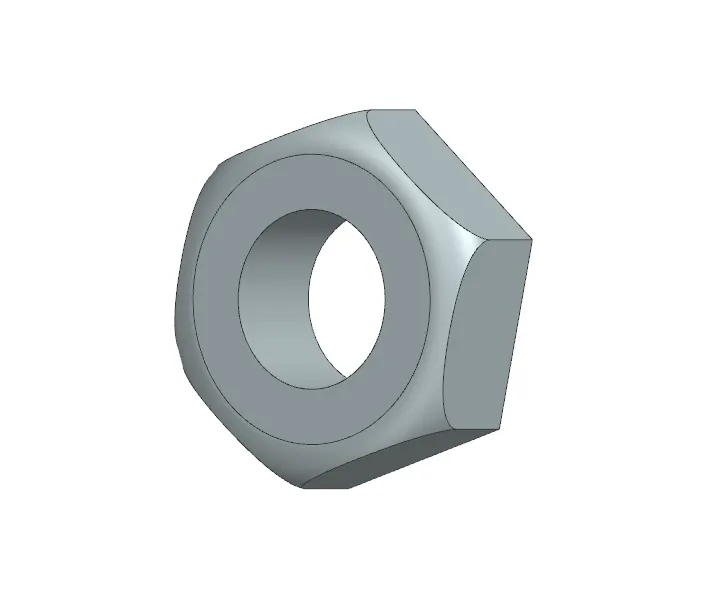
5. NUT
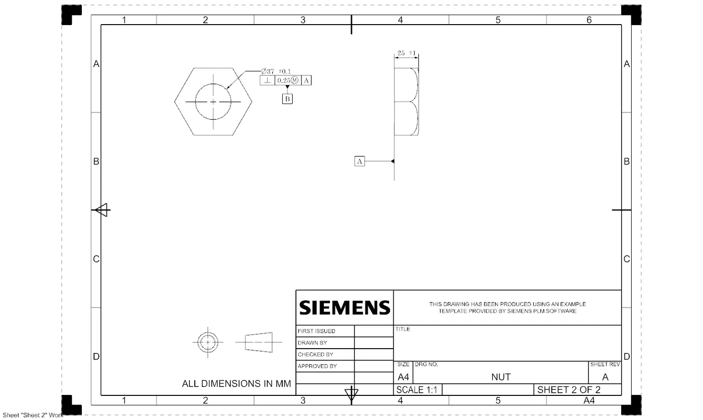
Hex Nut is also used to tightened with stem and one face is butt on the retainer where we can also give flatness and then make it as a Datum A also the hole is perpendicular with respect to datum A as shown in the drawing below
6. Stem for valve :The stem connects the lever to the valve disk and transmits the torque required to open and close the valve. The design must account for various environmental factors and operational stresses .
The design consideration for a valve stem is as follows :-
- Material :- The stem should be strong enough to transmit necessary torque without any failure also it must resist bending twisting or shearing force during operation , common materials like stainless steel , carbon steel or high strength alloys like inconel are typically used. The material must resist corrosion having high temp. resistance and wear resistance .
- Torque Transmission :- The stem must be design to transmit required torque from the actuator or handle .
- Stem to disk connection:- The connection is critical for the reliable operation between the stem and the disk. There are different methods of connections
b. Pinned Connections :- It is used for Smaller valve .
c. Bolted or set screw connection:- In some design the disk may be bolted or clamped onto the stem.
- Stem bearing and support:- To reduce the friction and wear especially in larger valves . The stem may require bearing or bushing . For bearing materials like bronze or PTFE coated bushing to minimize frication also in some design lubrication also used to ensure smooth operation .
- Cost and manufacturability :- The design should be made to make ease of manufacturing of stem including process like machining ,forging or casting .Also tight tolerance may be required for critical dimensions such as the stem diameter or sealing surfaces to ensure proper fit and function .
The drawing of stem of valve as shown :-
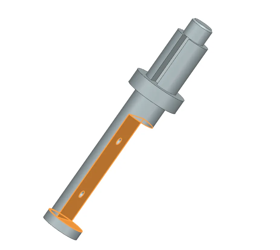
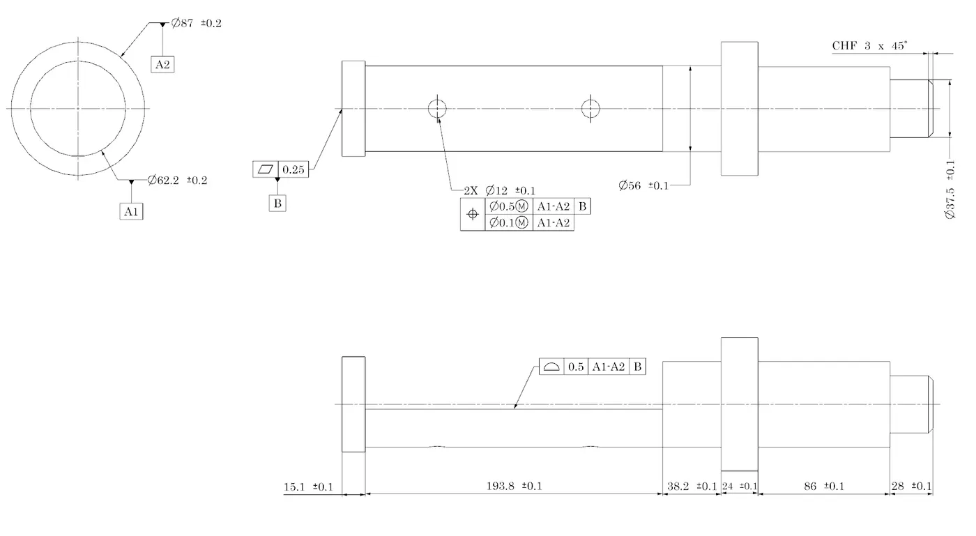 Giving tight tolerance to dia 62.2 and 87 of bilateral 0.2 mm as shown in the drawing snapshot making it as a datum A1 & A2. The bottom face is giving a flatness of 0.25 mm and making it as a datum B. Now the disk having two hole at a certain distance is getting fixed with the shown two hole on the stem so the position with other two datum and combine datum A1 & A2 is important which is given as shown. Also the profile of a surface is also important because the disk will be seated on that surface so giving tolerance of 0.5 mm as shown