Week 14 challenge
Report On Butterfly Valve Assembly:
Aim:
- To Assemble and apply GD&T to the butterfly valve assembly drawing.
Software: Siemens NX
Commands Used:
- Datum Plane,line,arc,circle,pattern,Dimension,sketch,Revolve,Unite,Assembly Constraints, Datum Feature Symbol, Datum Target, Feature Control Frame, Arc, Cross hatch, Note, Section View, Rapid Dimension.
Introduction:
- Operation is similar to that of a ball valve, which allows for quick shut off. Butterfly valves are generally favoured because they cost less than other valve designs, and are lighter weight so they need less support. The disc is positioned in the centre of the pipe. A rod passes through the disc to an actuator on the outside of the valve. Rotating the actuator turns the disc either parallel or perpendicular to the flow. Unlike a ball valve, the disc is always present within the flow, so it induces a pressure drop, even when open.
- A butterfly valve is from a family of valves called quarter-turn valves. In operation, the valve is fully open or closed when the disc is rotated a quarter turn. The "butterfly" is a metal disc mounted on a rod. When the valve is closed, the disc is turned so that it completely blocks off the passageway. When the valve is fully open, the disc is rotated a quarter turn so that it allows an almost unrestricted passage of the fluid. The valve may also be opened incrementally to throttle flow.
- There are different kinds of butterfly valves, each adapted for different pressures and different usage. The zero-offset butterfly valve, which uses the flexibility of rubber, has the lowest pressure rating. The high-performance double offset butterfly valve, used in slightly higher-pressure systems, is offset from the centre line of the disc seat and body seal (offset one), and the centre line of the bore (offset two). This creates a cam action during operation to lift the seat out of the seal resulting in less friction than is created in the zero offset design and decreases its tendency to wear. The valve best suited for high-pressure systems is the triple offset butterfly valve. In this valve, the disc seat contact axis is offset, which acts to virtually eliminate sliding contact between disc and seat. In the case of triple offset valves the seat is made of metal so that it can be machined such as to achieve a bubble-tight shut-off when in contact with the disc.
Types:
- Concentric butterfly valves
- Doubly-eccentric butterfly valves
- Triply-eccentric butterfly valves
Applications:
- In the pharmaceutical, chemical, and food industries, a butterfly valve is used to interrupt product flow (solid, liquid, gas) within the process. The valves used in these industries are usually manufactured according to cGMP guidelines (current good manufacturing practice). Butterfly valves generally replaced ball valves in many industries, particularly petroleum, due to lower cost and ease of installation, but pipelines containing butterfly valves cannot be 'pigged' for cleaning.
Why GD&T?
- GD&T is an international language used on engineering drawings. By providing uniformity in drawing specifications and interpretation, geometric dimensioning and tolerancing reduces controversy, guesswork, and assumptions throughout the manufacturing and inspection process. Used properly, GD&T improves communication, results in better product design, and increases product tolerances. It can save your organization time and money.
Components Of Butterfly Valve:
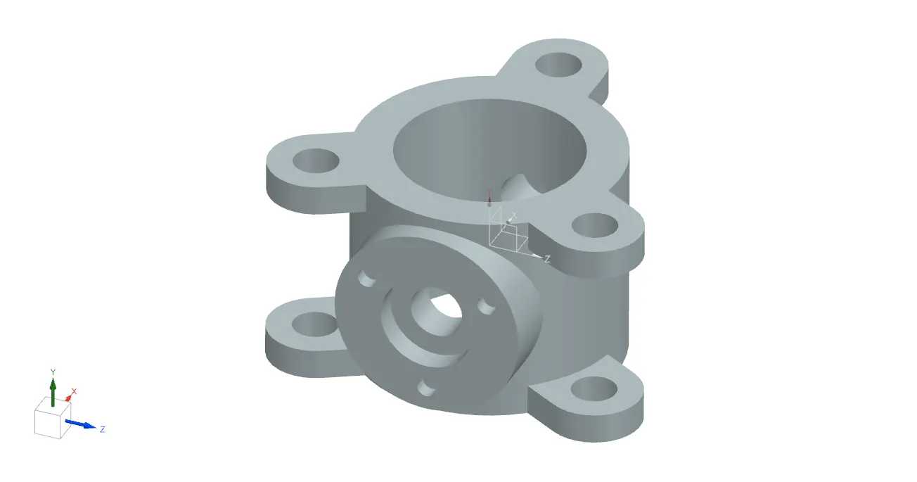
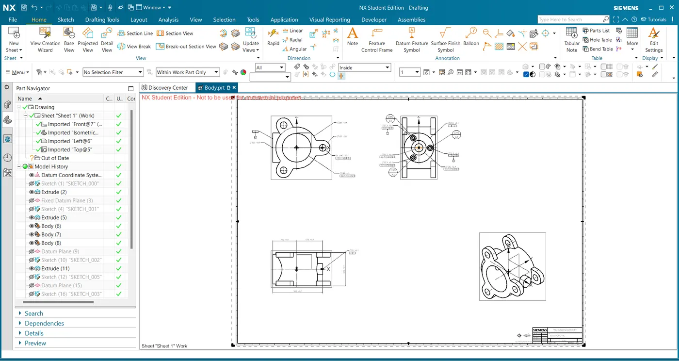
1.Body:
- Body of the butterfly valve is the main part to which all other parts are fixed
- Sketch of the body of butterfly valve is created and extrude it.
- create the sketch of the flange, pattern it and extrude them.
- Move the flanges to the other end also.
- create a support for retainer fixture and counter bore hole for shaft.
Drafting Sheet Of Body with GD&T:
2.Shaft:
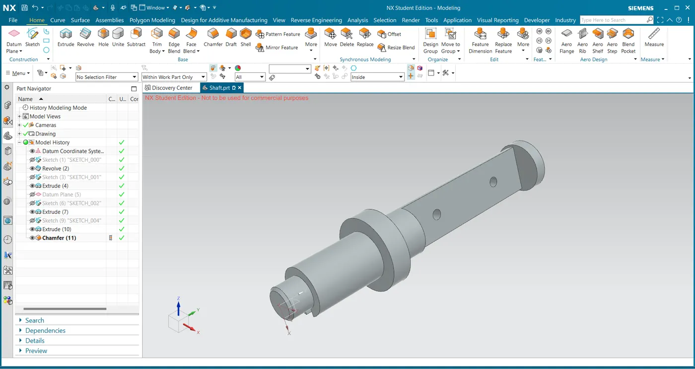
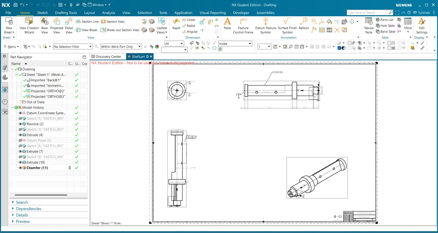
- Shaft is the part which is fixed to the body and disc part of the butterfly valve.
- Create the sketch of the shaft and extrude it.
- Provide the cut-out on the shaft for disc.
- To fix the disc on to the shaft drill hole on the shaft of 12.5mm Dia.
- Provide Chamfer on the shaft.
Drafting Sheet Of Shaft with GD&T:
3.Retainer:
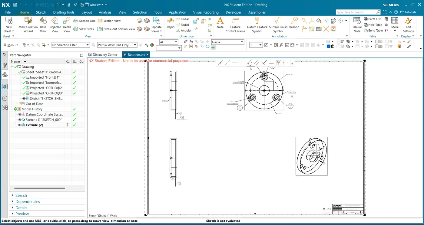
- Retainer is the part which is used to support the shaft and body.
- create the sketch of the retainer and extrude it.
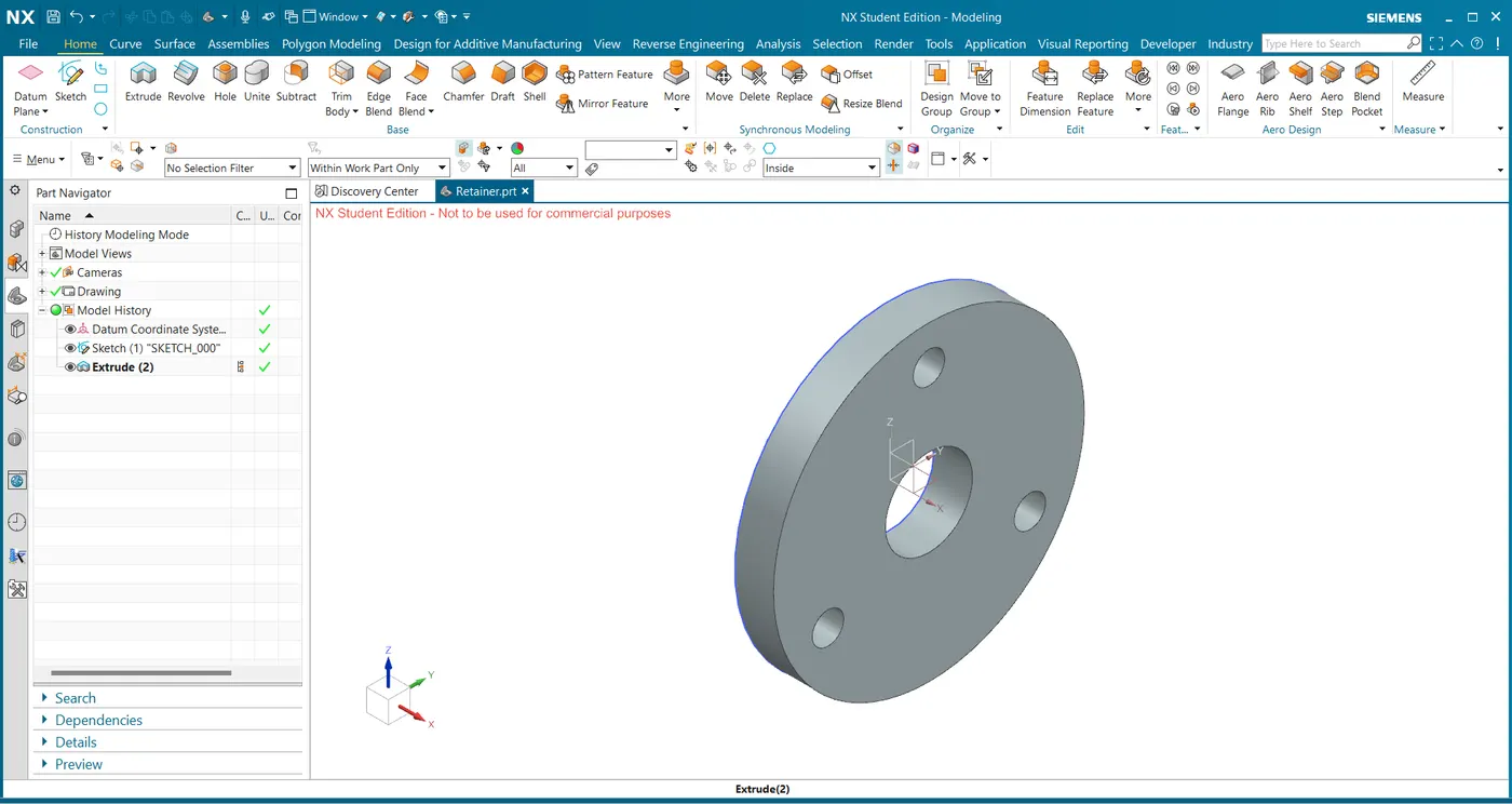
Drafting Sheet Of Retainer with GD&T:
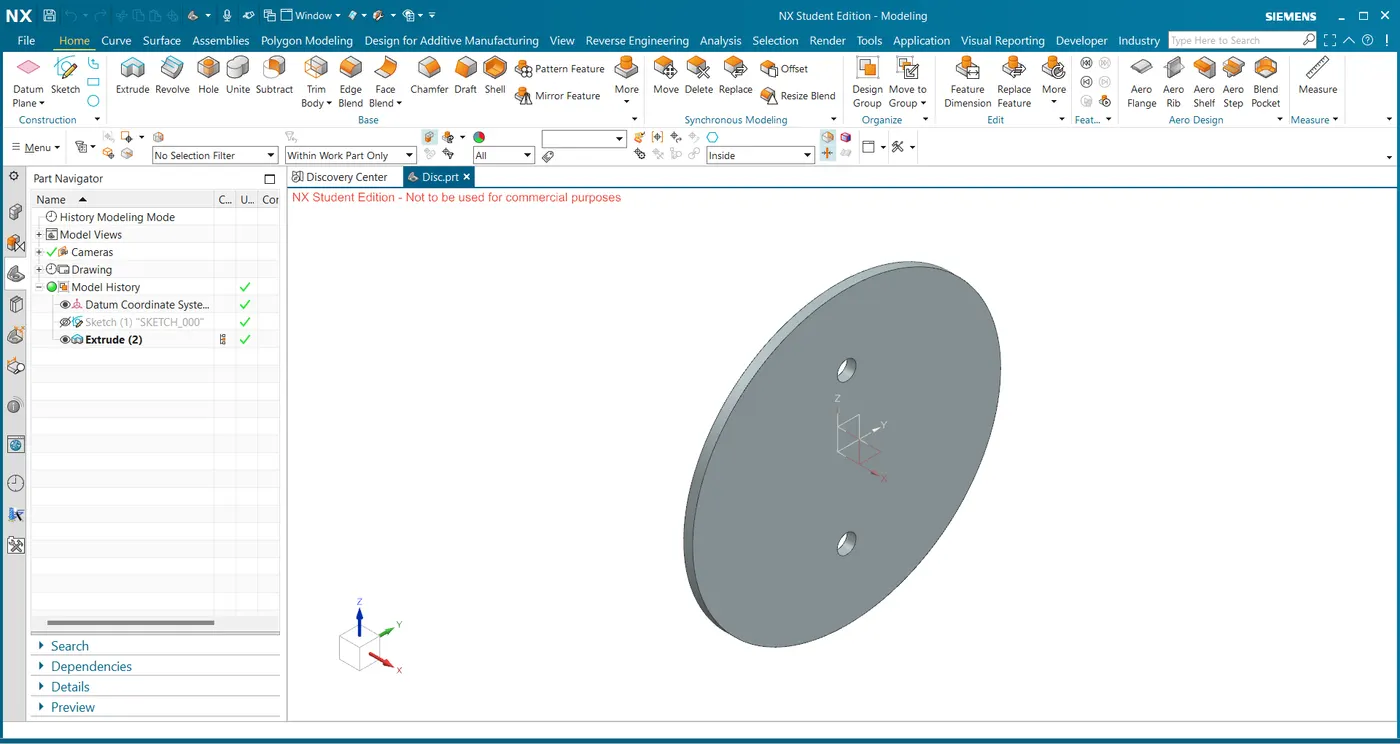
4.Disc:
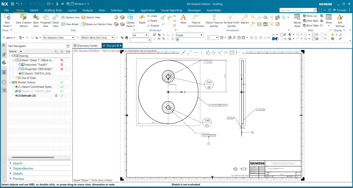
- Disc is the part used as fixture on the shaft to allow the flow of liquid/Fluid.
- Create the sketch of the disc and extrude it.
Drafting Sheet Of Disc with GD&T:
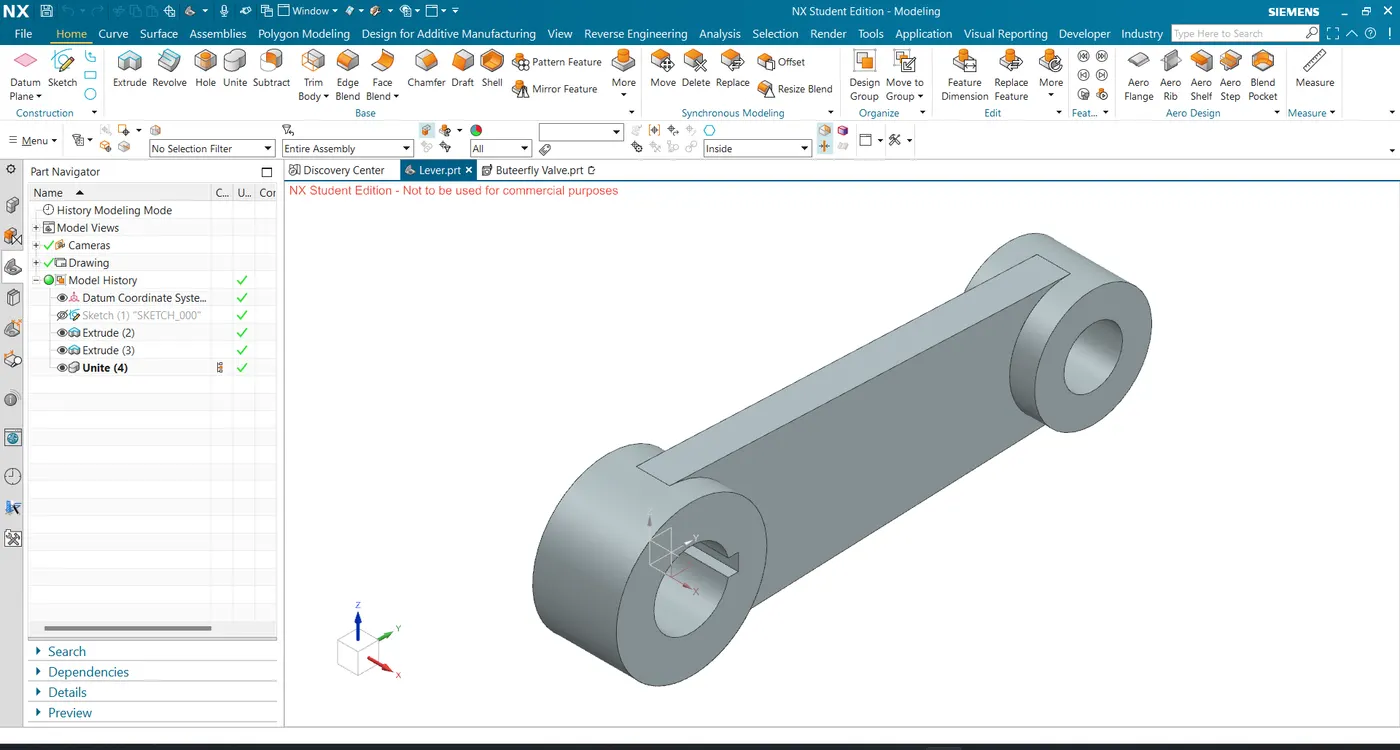
5.Lever:
- Lever acts as handle of butterfly valve to open and close the valve.
- Create the sketch of the lever and extrude it.
- Provide Keyset on the lever to lock the shaft using Key.
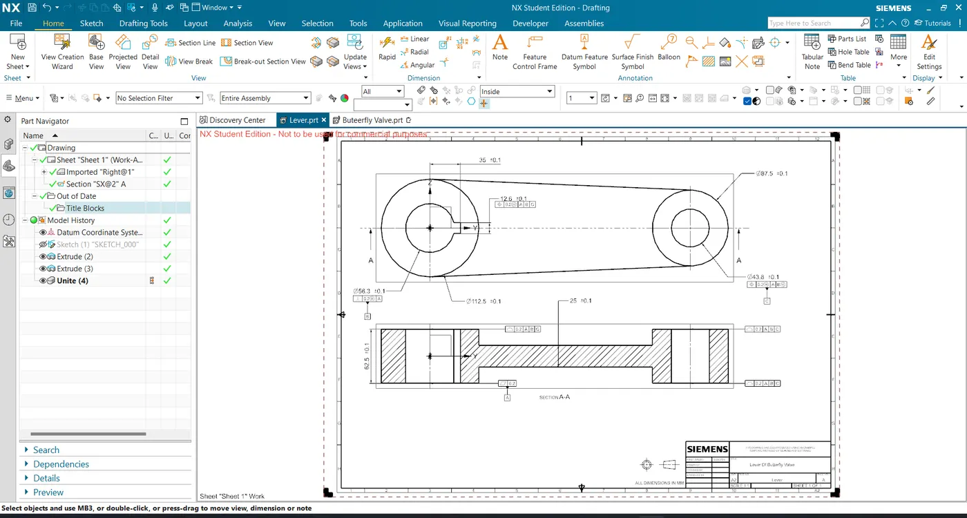
Drafting Sheet Of Lever with GD&T:
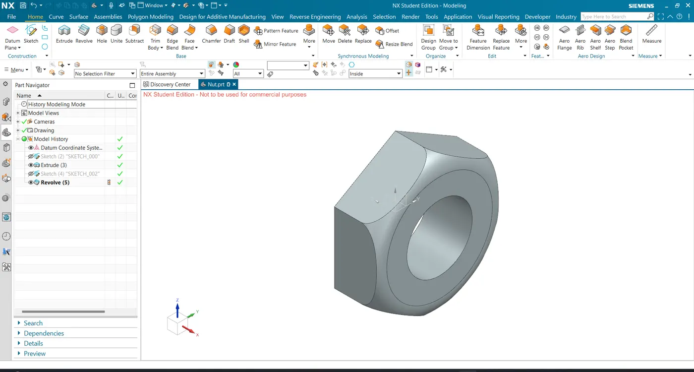
6.Nut:
- Nut is used to lock the parts of butterfly valve.
- Create the sketch of the nut and extrude it.
- Provide the radius of 10mm on the nut.
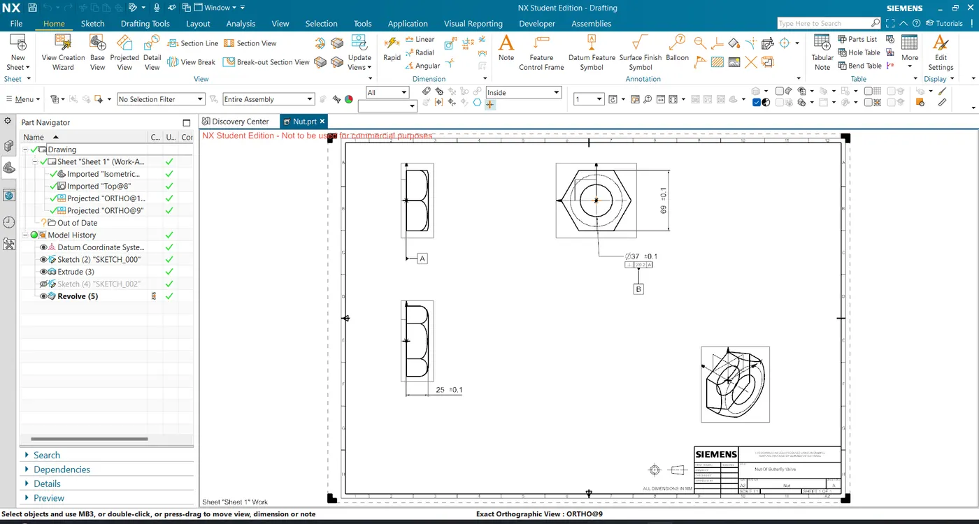
Drafting Sheet Of Nut with GD&T:
BUTTERFLY VALVE ASSEMBLY:
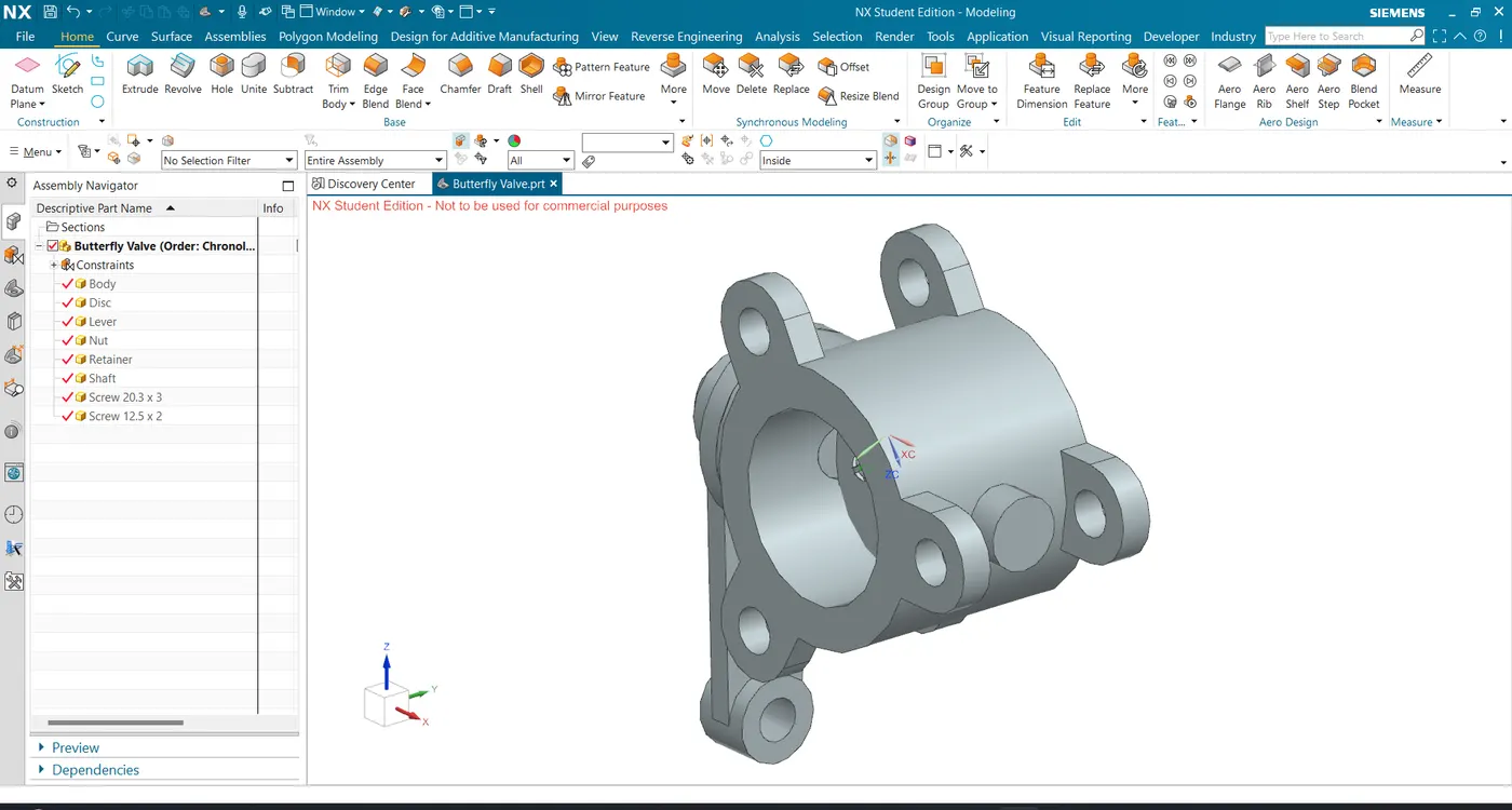
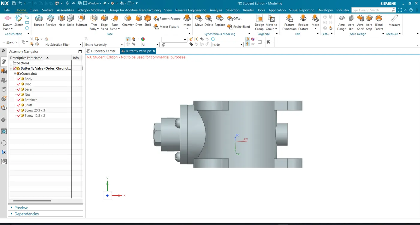
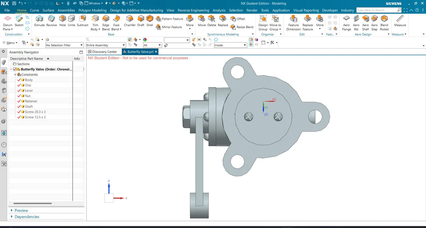
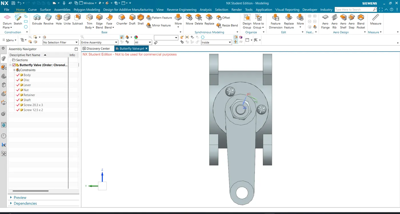
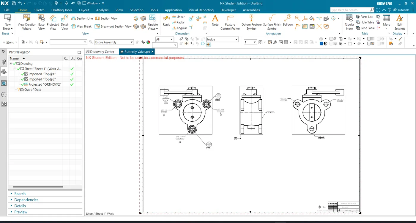
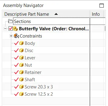
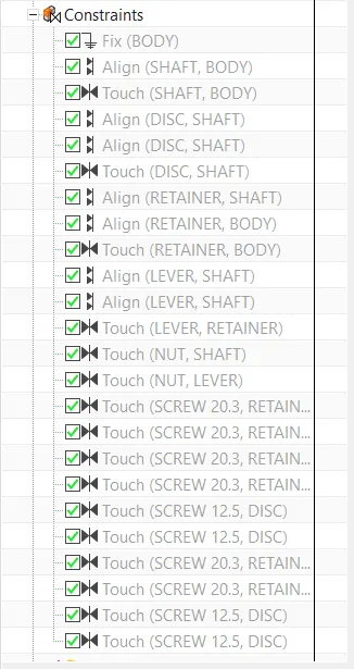
- All the parts of the butterfly valve are assembled together using assembly constraints such as Fix, Align, Touch.
Views:
Isometric View:
Top View:
Front View:
Side View:
Drafting Sheet Of Butterfly Valve with GD&T:
Assembly Navigator:
Assembly Constraints used to assemble the Butterfly Valve:
Result:
- All the parts of the butterfly valve are designed.
- All the Parts of Butterfly Valve is assembled together and GD&T is applied to the butterfly valve assembly drawing.