Week 14 challenge
Objective
To Assemble the Butterfly valve using the parts made with the help of Siemens NX software and also apply GD&T to the assembly.
INTRODUCTION
Butterfly valves are a family of quarter-turn rotational motion valves that are used in pipelines to shut-off flow. It is often said that butterfly valves can be used to regulate the flow. However, we do not recommend doing this, as it can damage the valve disk and have a negative effect on the sealing properties. They are used in a wide variety of process media and industries especially in water supply, collection, and distribution, as well as pumping stations, and have a broad range of use cases especially in flow isolation. A couple of their key advantages over other valve families are there,
<!-- [if !supportLists]-->· <!--[endif]-->Simple construction and compactness
<!-- [if !supportLists]-->· <!--[endif]-->Lighter weights
<!-- [if !supportLists]-->· <!--[endif]-->Lower cost
<!-- [if !supportLists]-->· <!--[endif]-->Smaller installation footprints
<!-- [if !supportLists]-->· <!--[endif]-->Faster actuation speeds
The "butterfly" is a metal disc mounted on a rod. When the valve is closed, the disc is turned so that it completely blocks off the passageway. When the valve is fully open, the disc is rotated a quarter turn so that it allows an almost unrestricted passage of the fluid. The valve may also be opened incrementally to throttle flow.
There are different kinds of butterfly valves, each adapted for different pressures and different usage. The zero-offset butterfly valve, which uses the flexibility of rubber, has the lowest pressure rating. The high-performance double offset butterfly valve, used in slightly higher-pressure systems, is offset from the center line of the disc seat and body seal (offset one), and the center line of the bore (offset two).
The Butterfly Valve is an assembly of 6 part which are listed as below,
<!-- [if !supportLists]-->1. <!--[endif]-->Main body
<!-- [if !supportLists]-->2. <!--[endif]-->Shaft
<!-- [if !supportLists]-->3. <!--[endif]-->Retainer
<!-- [if !supportLists]-->4. <!--[endif]-->Disc plate
<!-- [if !supportLists]-->5. <!--[endif]-->Nut
<!-- [if !supportLists]-->6. <!--[endif]-->Screw
With the help of all these parts we create an assembly called as butterfly valve which is used to control the flow.
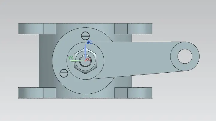
<!-- [if !supportLists]-->· <!--[endif]-->Butterfly valve main body
Butterfly valve main body is the base part of the Butterfly valve which is connected between the pipe. All the other parts of the butterfly valves are attached with the main body.
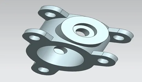
<!-- [if !supportLists]-->· <!--[endif]-->shaft - Butterfly valve
The shaft is the part of the Butterfly valve which is used to control the flow of fluid into the valve with the help of a disc attached to it. The shaft is rotated with the help of the Lever to provide a specific amount or flow of fluid to the other end.
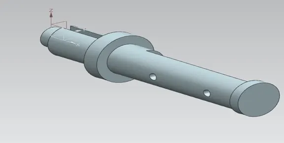
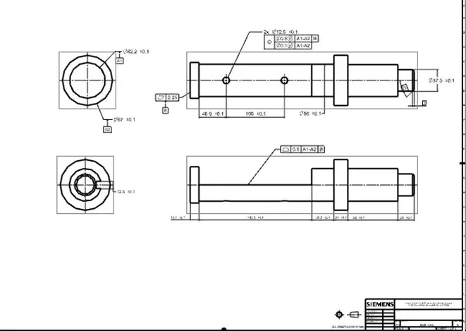
The GD&T is applied to the part as shown below,
<!-- [if !supportLists]-->· <!--[endif]-->Retainer plate
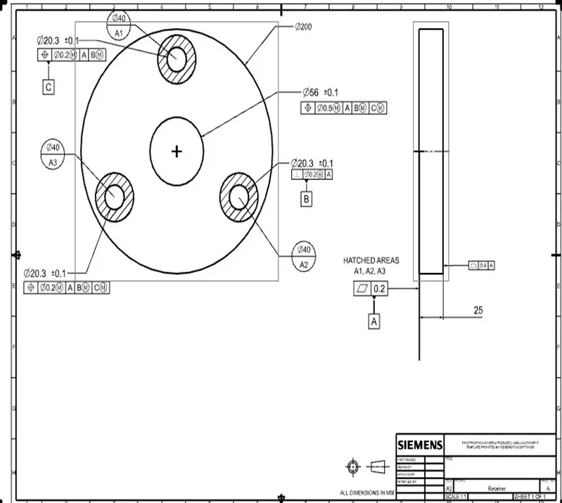
The retainer plate is the part of the Butterfly valve attached to it at the top. It is used to mount the shaft or stem of the butterfly valve and also close the top of the butterfly valve.
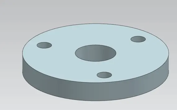
The GD&T is applied to the part as shown below,
<!-- [if !supportLists]-->· <!--[endif]-->DISC plate
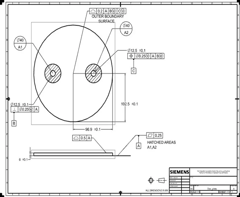
The Disc plate is the part of the Butterfly valve that is attached to the shaft and block or allows the fluid. It is used to control the fluid flow through the butterfly valve with the help of the shaft or stem of the butterfly valve.
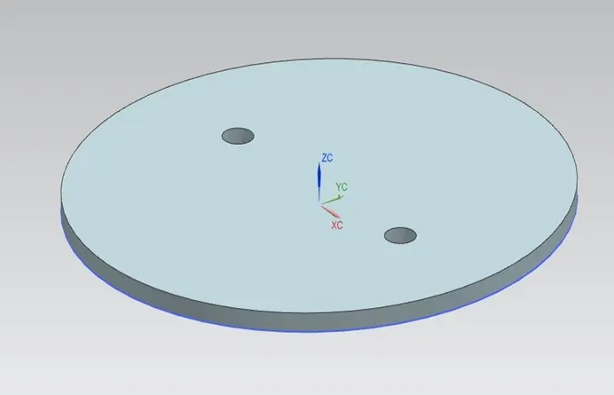
The GD&T is applied to the part as shown below,
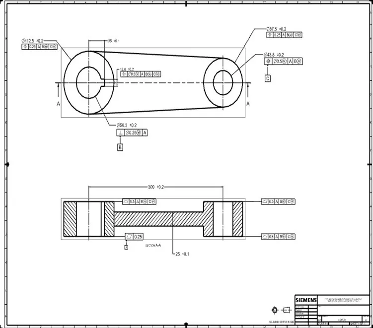
<!-- [if !supportLists]-->· <!--[endif]-->lever
The Lever is the part of the Butterfly valve attached to the shaft of the butterfly valve and controls the movement of the shaft.
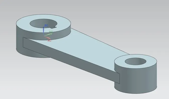
The GD&T is applied to the part as shown below,
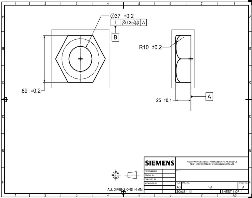
<!-- [if !supportLists]-->· <!--[endif]-->Nut
The Nut is the part of the Butterfly valve attached to the Lever of the butterfly valve by which it joins the lever with the shaft.
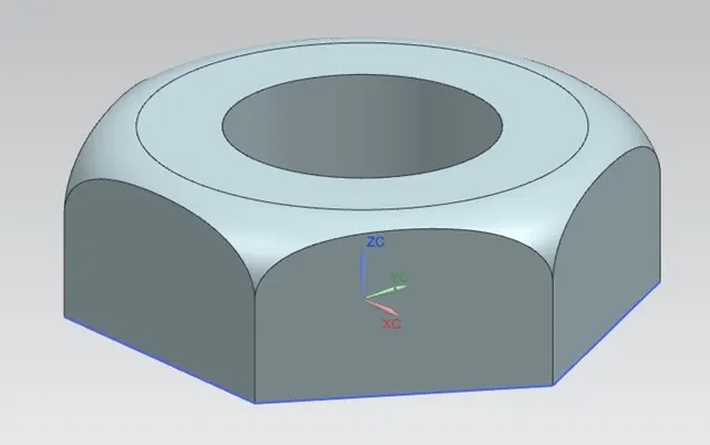
The GD&T is applied to the part as shown below,
<!-- [if !supportLists]-->· <!--[endif]-->SCREW
Screw is used to fix the disc plate with the shaft and also used to fix the retainer plate with the main body as shown below in the image,
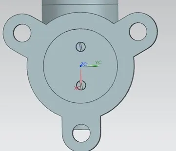
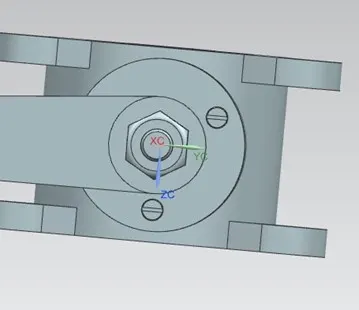
As shown above, all the parts are assembled together to make a Butterfly valve which is used to control flow of fluid between two pipes.
ASSEMBLY- BUTTERFLY VALVE
To assembly the Butterfly valve we are following the below steps,
<!-- [if !supportLists]-->· <!--[endif]-->To assemble the butterfly valve firstly we have to save all parts in same folder from where we can access all that files.
<!-- [if !supportLists]-->· <!--[endif]-->After that we open an assembly file in the software and add all the parts in the assembly workbench.
<!-- [if !supportLists]-->· <!--[endif]-->After that we separate all the parts with the help of move command in assembly workbench.
<!-- [if !supportLists]-->· <!--[endif]-->After that we start to assemble the disc plate to the shaft with the help of Assembly constraints.
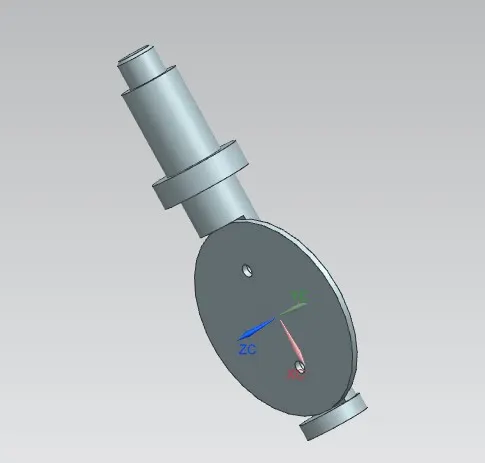
<!-- [if !supportLists]-->· <!--[endif]-->After that we fasten the screw to the disc with the help of assembly constraints.
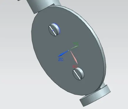
<!-- [if !supportLists]-->· <!--[endif]-->After that we assemble the above assembled parts with the Main body of the butterfly valve as shown below,
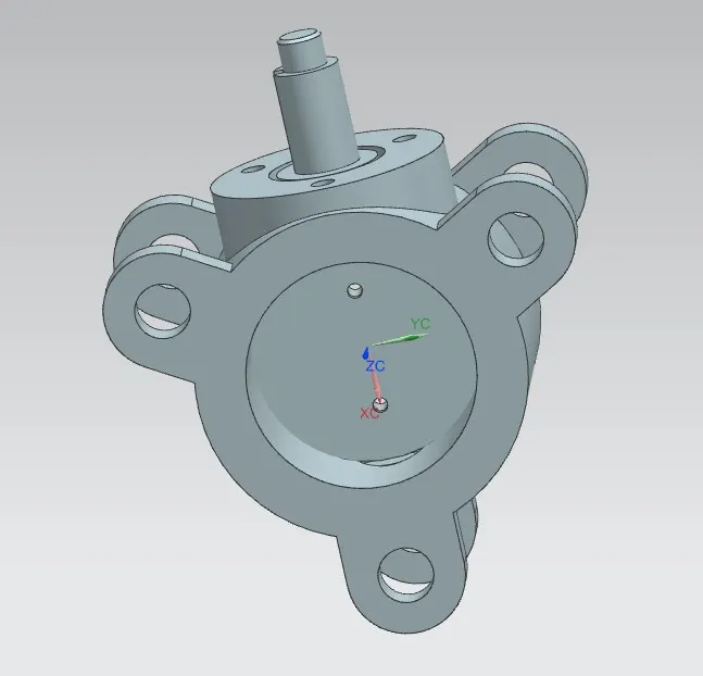
<!-- [if !supportLists]-->· <!--[endif]-->After this we assemble the retainer plate with the above assembly with the help of assembly constraints.
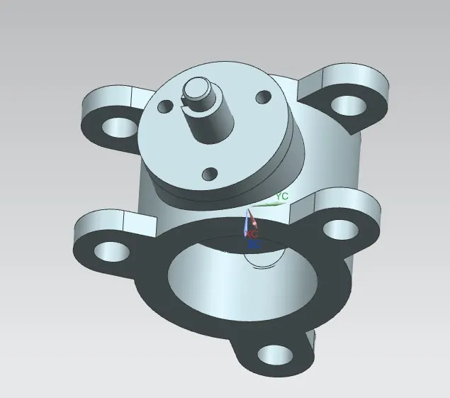
<!-- [if !supportLists]-->· <!--[endif]-->The retainer plate is also screwed just like the disc plate
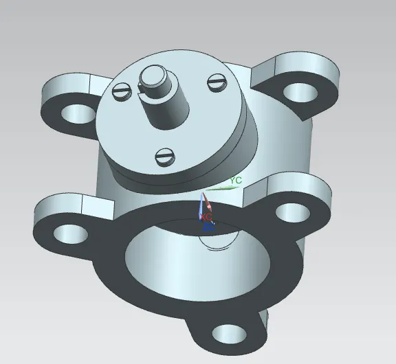
<!-- [if !supportLists]-->· <!--[endif]-->Now the lever is assembled with the above assembly for that we used the slot and centre axis of the lever as a reference.
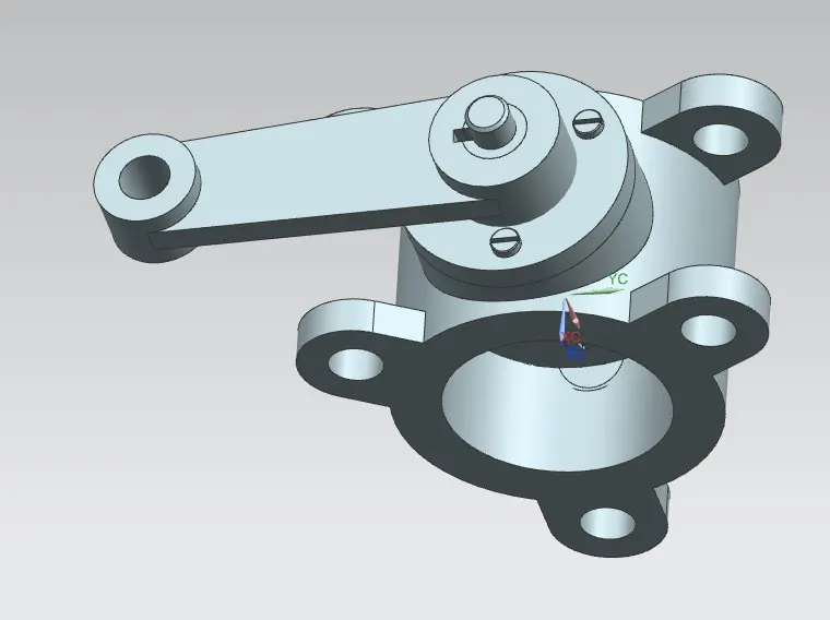
<!-- [if !supportLists]-->· <!--[endif]-->After the assembly of the lever the final part NUT is attached on it to lock the all parts and the assembly is completed.
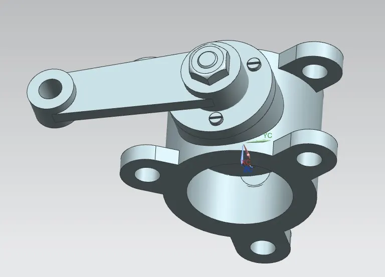
<!-- [if !supportLists]-->· <!--[endif]-->Now we apply the GD&T to the above Butterfly assembly and created a 2D sheet to show the GD&T applied,
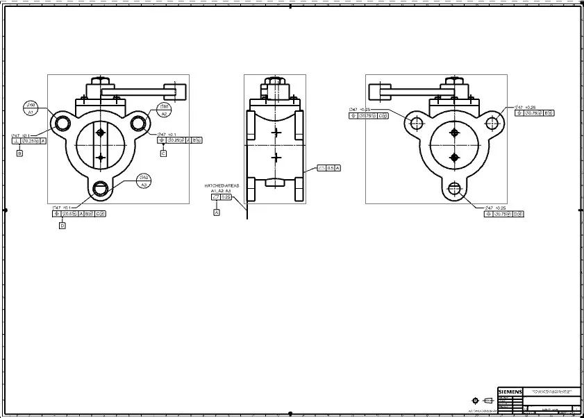
ISOMETRIC VIEW
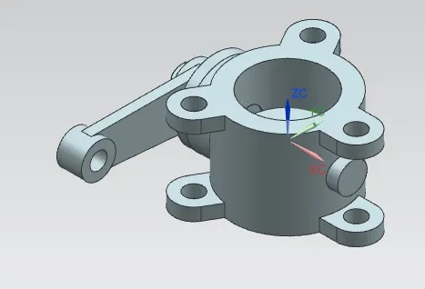
TOP VIEW
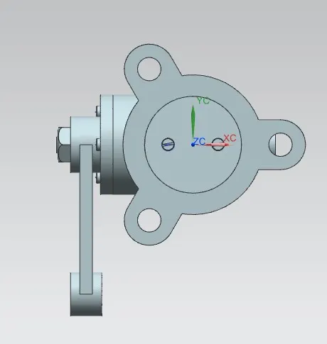
FRONT VIEW
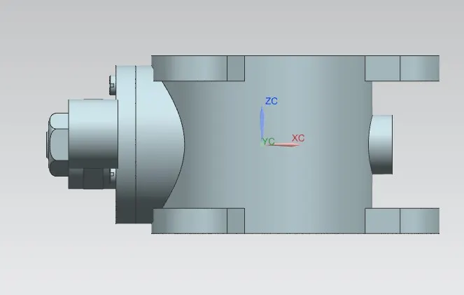
SIDE VIEW