Week 14 challenge
ASSEMBLE ALL THE CAD PARTS OF BUTTERFLY VALVE AND THEN WE NEED TO APPLY GD&T TO IT:
BUTTER FLY VALVE: Butterfly valves are a family of quarter-turn rotational motion valves that are used in pipelines to shut-off flow. It is often said that butterfly valves can be used to regulate the flow. However, we do not recommend doing this, as it can damage the valve disk and have a negative effect on the sealing properties.
USES OF BUTTERFLY VALVE: Butterfly valves are used where space is limited. Unlike gate valves, butterfly valves can be used for throttling or regulating flow as well as in the full open and fully closed position. The pressure loss through a butterfly valve is small in comparison with the gate valve.
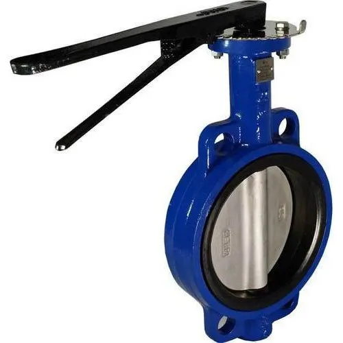
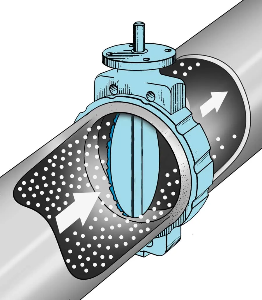
ASSSMBLY OF BUTTERFLY VALVE:
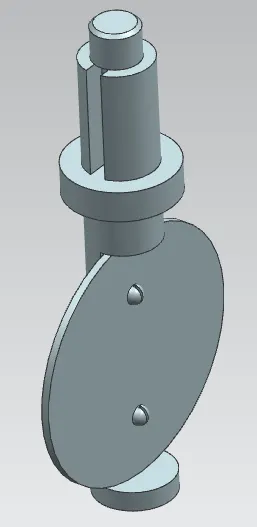
First we will assemble the disc palte with shaft by using assembly constarin as we will align axis of the screw hole of disc plate with screw hole of shaft and then we will give touch constrain for the face of shaft and bottom of the discplate and then we will assemble the screws into the holes of the shaft and disc plate and we will recieve the output as follows:
after that we will assemble this with the body but before that we will fix our body using fix constrain and then we will assemble the shaft assembly with the body using axis align and and touch constrain and then we weill recieve the output as follows:
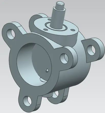
after assembling the shaft with the main body we will assemble the retrainer on the top of the body using align axis and the touch command and then we will reciev e the output as foloows:
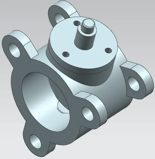
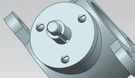
after this we will assemble the screw for the retainer as we did prior for the shaft and then we will recieve the output as follows:
and then we will assemble the lever and the nut by using same constrain and then we will recieve the output as follows:
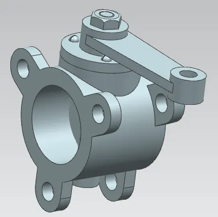
once if we done upto this much our butterfly valve assembly is completed.
now we will apply GD&T to the butterfly valve.
APPLYING GD&T TO THE BUTTERFLY VALVE:
Applying GD&T in the sense we will take control on all the six degrees of freedom of the part. so we will apply GD&T by using some kind of tolerence and and datums.
so for this prt we will appy datum A which will arrest 3 degrees of freedom basically A datum is datum which will be the surface which will get in contact with its mating surface first
so here the surface near the holes on the body is going to be datum A if we apply datum A to the whole surface it will cost too much because we will give some amount of flattness tolerence to it so it will cost too much.
so we will use datum symbol to locate datum A and then we will apply datum B and C for datum B we will select one of the hole and we will give a size tolerence first and then we will give a perpendicularity tolerence of 0.25at maximum material condition a with respected to datum A and then we will apply datum C to other hole and then we will give size tolerence to it and then we will give a position tolerence of 0.25mm at max material condition with respect to datum A and B with max material boundary.
and then we will give a size and position tolerence of 0.25mm at max material condition with respected to datum A and datum B at max material bounady and datum C at max material boundary and then will name it as datum D because we have to control the opposite direction of the surface also.
and then we will apply we will give a position tolerence to all the holes of the opposite side with respect to datum B at maximum material boundary for the datum B hole and datum C at max material condition at datum C hole and datum D at max material condition with respect to datum D hole.
and then we will give a profile tolerence of 0.5mm with respect to datum A either we can give with respect to all datum or we can give only with respect to datum A.
THE FOLLOWING ARE THE GD&T APLLIED TO THE BUTTERFLY VALVE:
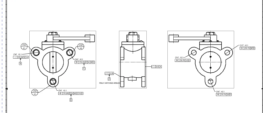
by this way we have applied datums and got control all over the surface
since we can apply some size tolerence to the liver and some other parts but it is not necessary so we didnt applied.