Week 14 challenge
DESIGN AND ASSEMBLE OF BUTTERFLY VALVE
OBJECTIVE:
To Design and create Assembly of Butterfly valve and also apply GD & T to the Butterfly valve Assembly drawing by using NX-CAD.
TOOL USED: NX-12
INTRODUCTION:
Butterfly valves are a quarter turn valve that is simple in design and easy to use. The components of butterfly valves are made up of four main parts: the body, disk, stem, and the seat.
PROCEDURE:
STEP_1: MODELING WORKBENCH
3D MODEL_ BODY OF THE BUTTERFLY VALVE
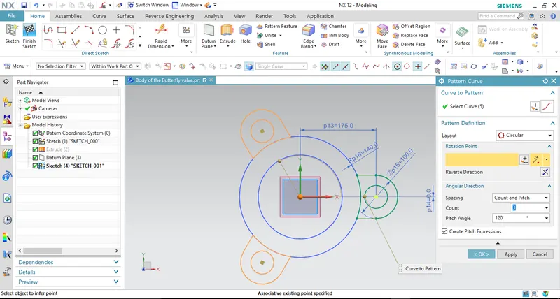
Craating body base sketch curve then apply Extrude.

Creating flange sketch on one of its side by Extrude then apply mirror feature along with the defined plane will get on oppsite end.
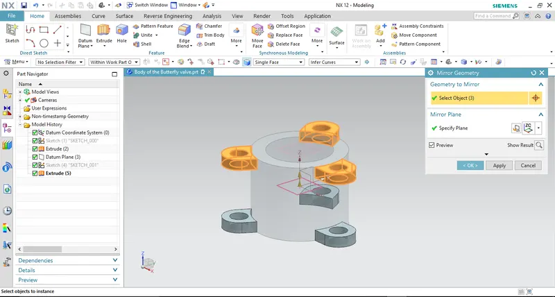
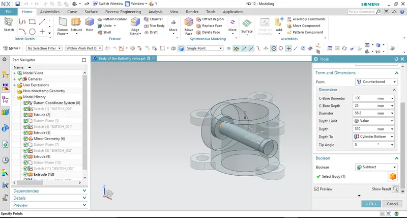
Creating counter bore hole by defining hole feature definition.
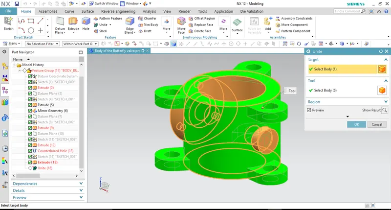
By defining Unite command thus the all bodies gets joined into single part body.
3D MODEL_ SHAFT/STEM OF THE BUTTERFLY VALVE
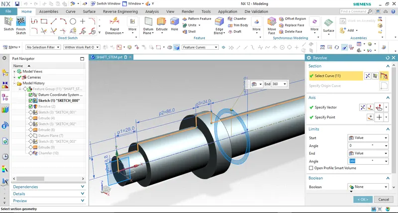
Create base sketch curve of the shaft section then by defining Revole feature along with specified axis which will results as like below,
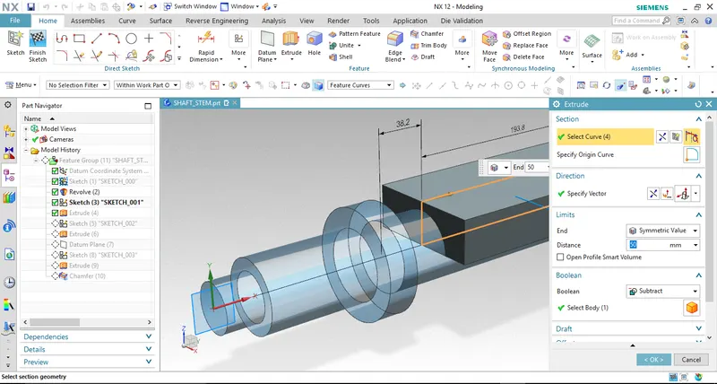
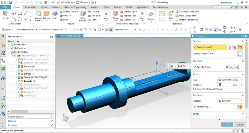
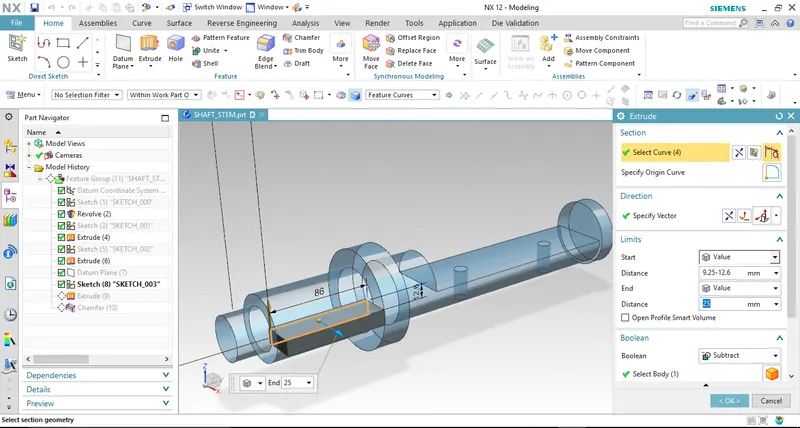
By defining Extrude with subtract boolean operation.
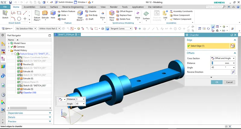
By defining Chamfer feature.
3D MODEL_ DISC PLATE OF BUTTERFLY VALVE
Creating base sketch curves.
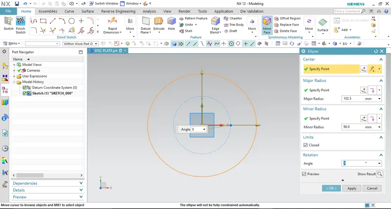
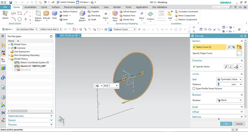
By defining Extrude feature.
3D MODEL_ RETAINER OFBUTTERFLY VALVE
Creating base sketch curves.
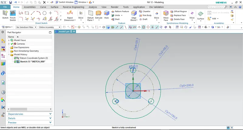
By defining extrude feature.
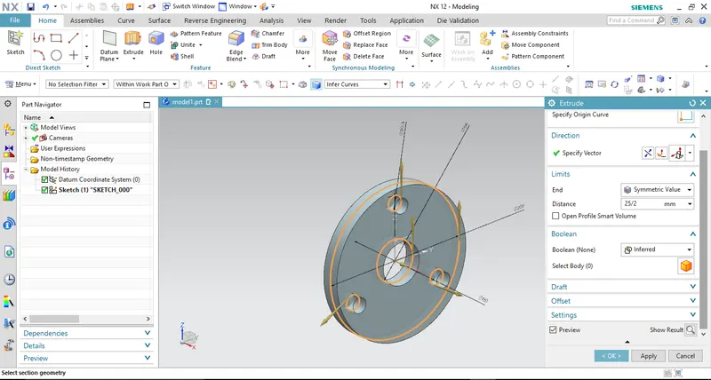
3D MODEL_ HANDLE OF BUTTERFLY VALVE
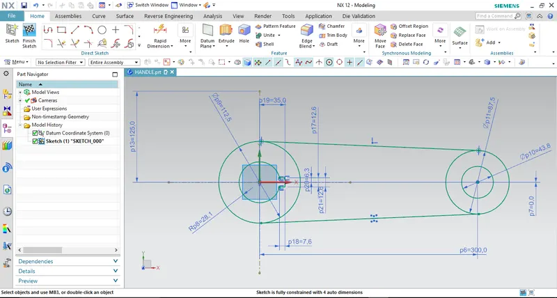
Create base sketch curves.
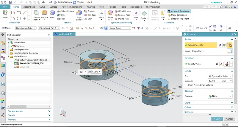
Defining Extrude feature applied on circular sketches then the other closed contour gets extruded.
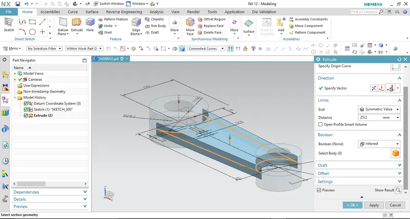
By defining Unite to join the part bodies into Single Object.
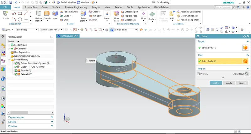
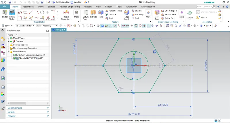
3D MODEL_NUT OF BUTTERFLY VALVE
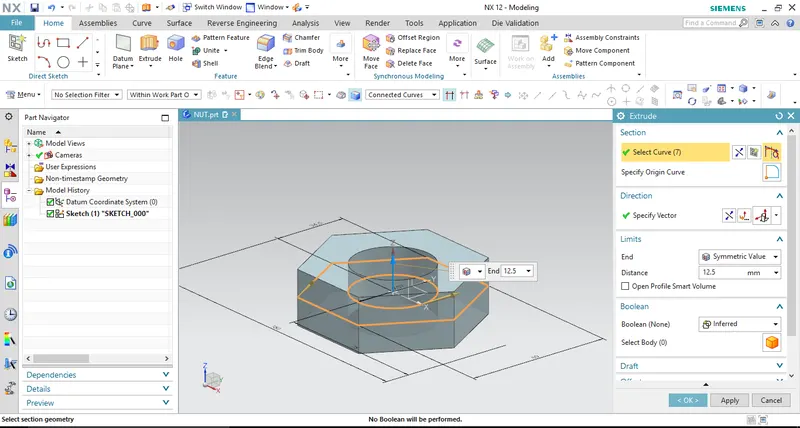
Creating base sketch then applying Extrude definition.
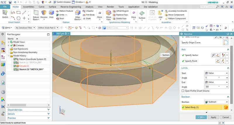
Applying revole feature thus the part body gets cut by defined sketch object with subract boolean operation.
STEP_2: ASSEMBLY WORKBENCH
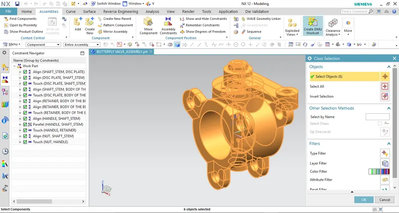
Adding all the Part bodies into Assembly workbench.
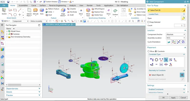
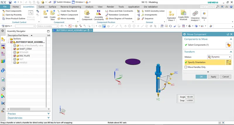
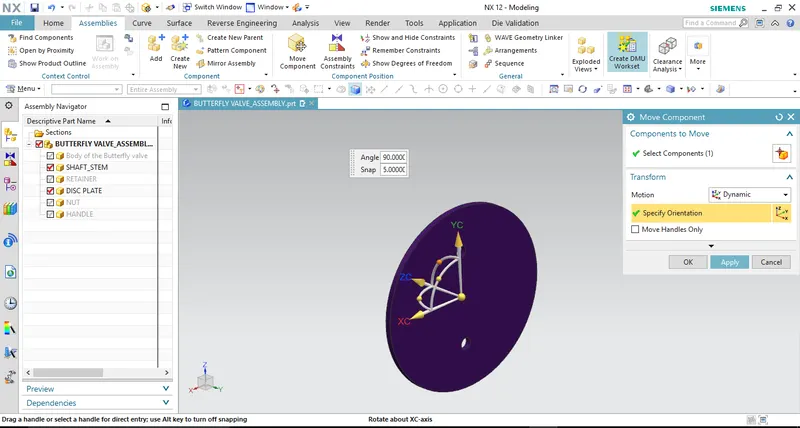
Defining Move component thus the objects gets move,rotate etc.,
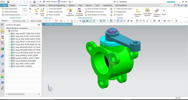
Defining Assembly Constrains like Align,Touch,Parallel,Fix,etc.,
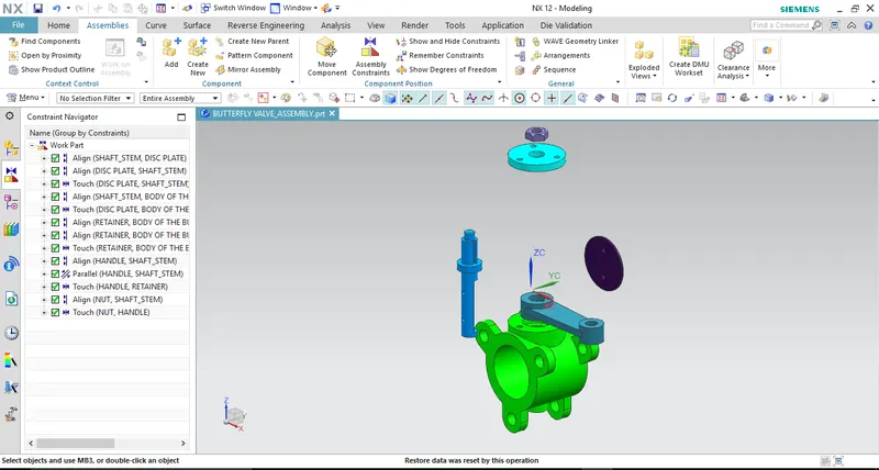
ASSEMBLY_EXPLODED VIEW:
EXPLODE VIEW:
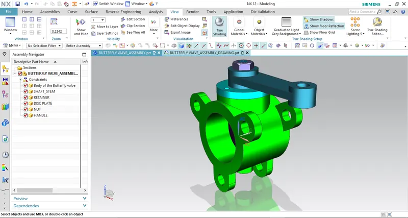
ASSEMBLY VIEW_BUTTERFLY VALVE:
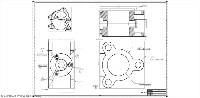
STEP_3: DRAFTING WORKBENCH & APPLYING GD &T
DRAFTING_ BODY OF BUTTERFLY VALVE
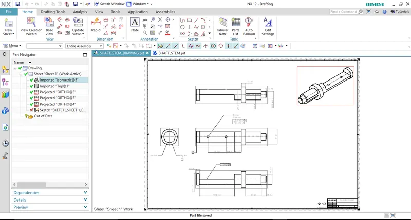
DRAFTING_SHAFT/STEM OF BUTTERFLY VALVE
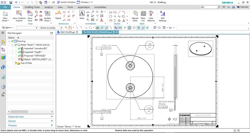
DRAFTING_ DISC PLATE OF BUTTERFLY VALVE
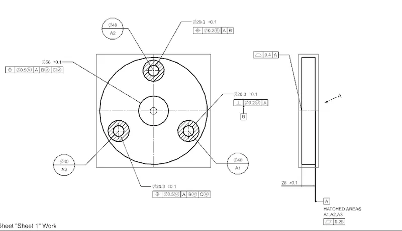
DRAFTING_RETAINER OF BUTTERFLY VALVE
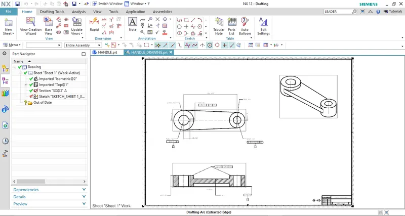
DRAFTING_HANDLE OF BUTTERFLY VALVE
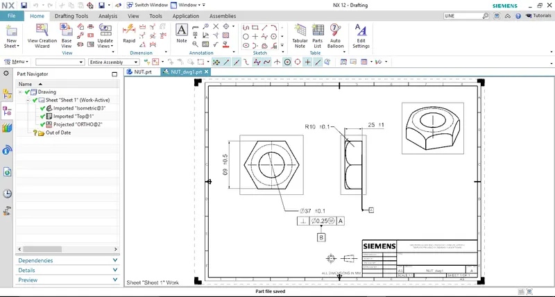
DRAFTING_NUT OF BUTTERFLY VALVE
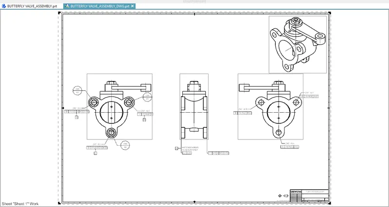
DRAFTING_ASSMBLY OF BUTTERFLY VALVE
CONCLUSION:
Thus the assembly design of Butterfly valve has to be done by using NX-CAD. And also Drafting & GD & T also applied on each of its parts and assembly completed.