Week 14 challenge
Objective -
To assemble and apply GD&T to the butterfly valve assembly drawing.
Tools used :-
- Assembly add component
- move
- allign contraints
- touch constraints
- drafting.
Steps followed :-
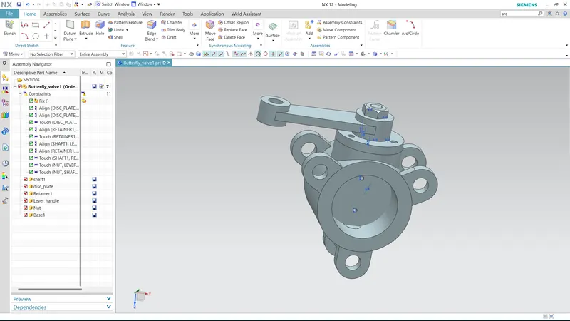
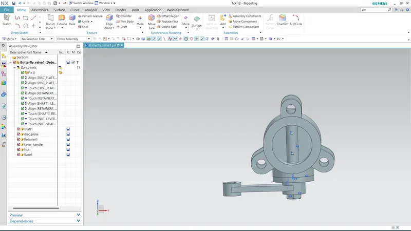
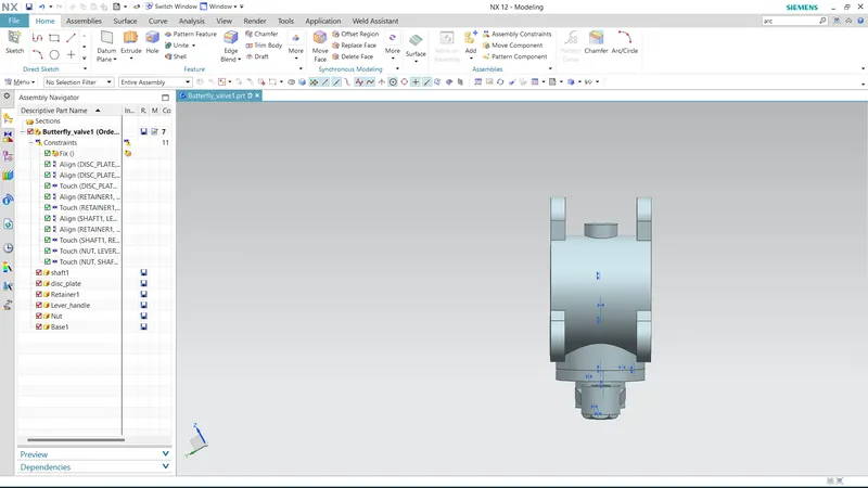
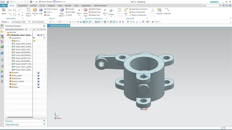
- First the different parts created for butterfly valve are imported to the assembly window.
- here all the imported parts of the valve are seperated individualy by move command.
- after moving the parts constraints are given to the parts one by one to allign with each other.
- At first the disc plate is attached to the shaft.
- after that it is alligned with the valve base and applied align constraints.
- Now the retainer plate is aligned with the base and touch constraints is applied.
- then lever is moved near the top of the base and allign constrain is applied, later touch constraint is given to the lever and base of the valve.
- At last nut is alligned with the shaft and touch constraint is applied to the nut and valve.
Drafting:
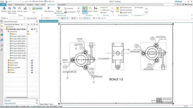
- For drafting first the A0 sheet is selected and since the drawing doesn't fit in the sheet so scale is set to 1:2.
- next the base view is added and datum target is marked to the holes as A1, A2 and A3.
- The marked datum target arc circle is drawn and hatched so that it appers more clearly.
- radial dimensions are provided to the each holes and feature frame with A1 is defined as perpendicularity of 0.25mm at maximum material condition at datum B and A
- position tolerance is given at A2 at datum c at maximum material condition and maximum boundry condition at B.
- Flatness tolerance of 0.25 is given at each outer holes.
- Profile tolerance is given at the outer face of the valve of 0.25 at datum A, B and C at maximum boundry condition.
- Now for the other side feature frame is defined for the position of tolerance 0.75mm at maximum material condition at datum B, C and D at mamimum boundry condition.