Week 14 challenge
Hi,
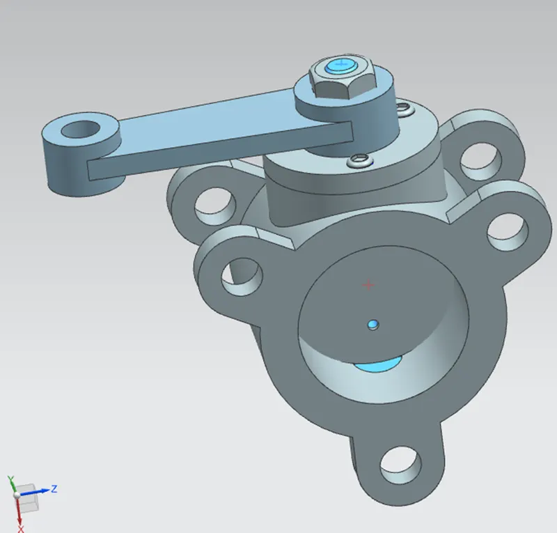
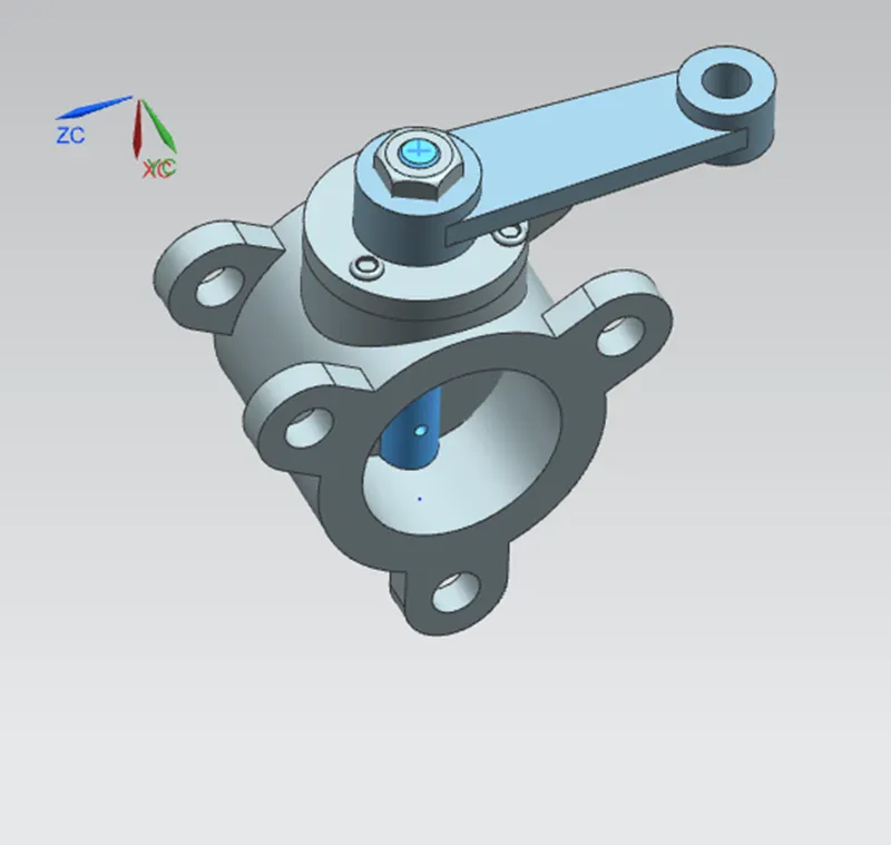
Here I have submitted the assembly constrains & GD&T on a drawing sheet of the butterfly valve assembly.
Procedure followed for butterfly valve assembly:
- The very first I have started with adding a new component to the assembly called butterfly valve head.
- Then inserted the disc plate & by using ‘assembly constrains’ mated the components by ‘prefer touch’ command.
- Then added the other component called retainer plate & added assembly constrains on the top of the head using ‘prefer touch’.
- Then adding the shaft to the assembly & mated on the axis of the retainer plate.
- Then added the lever & on the keyway slot side added the assembly constrains axially by using ‘prefer touch’
- And added the nut to the assembly & by using prefer touch constrained it on the axis of the shaft & on the surface of the lever.
- Finally added screws to the assembly, added on the top of the retainer plate on the three holes by using prefer touch on one hole.
- And copied the screws X3 using ‘move component’ tool & constrained the other screws accordingly.
Procedure followed for butterfly valve assembly GD&T drawing creation:
- First, I have started out with datum coordinate system using Datum CSYS tool.
- For applying GD&T to the assembly, I converted the part file to a drawing file using ‘drafting’ on an application toolbar.
- Then selected an A3 sheet size & filled up the title blocks.
- And created a base view as a top view & projected the side views accordingly.
- Then using ‘rapid dimension’ tool dragged the dimensions created on the assembly of lengths, diameters, hole callouts.
- Then created the side of the butterfly valve head as datum A.
- Then created the datum target areas on the front view of the butterfly valve head with the three 47 diameter holes.
- The datum target areas as 60 diameters of A1, A2, A3.
- And given flatness of the areas as 0.2.
- And defined the A1 hole as the perpendicularity of 0.2 at maximum material condition with respect to datum A & defined the hole as datum B.
- And given the position tolerance for the A2 hole of 0.2 at maximum material condition with respect to A & B at maximum material condition & defined the hole as datum C.
- And given the position tolerance for the A3 hole of 0.5 at maximum material condition with respect to A & B at maximum material condition & C at maximum material condition & defined the hole as datum D.
- And on the mirror view of it, defined the axis of the hole by the position of 0.7 at maximum material condition & datum B at maximum material condition.
- And defined the C datum hole as the position of 0.7 at maximum material condition & datum C at maximum material condition.
- And defined the D datum hole as the position of 0.7 at maximum material condition & datum D at maximum material condition.
- And finally, assigned the opposite surface of the butterfly valve head as the profile of 0.5 with respect to A & B at maximum material condition & C at maximum material condition.
- Thus applied GD&T for the butterfly valve assembly.
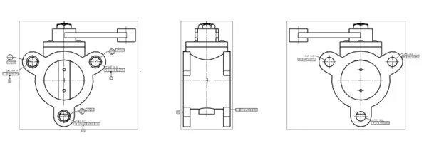
Thus, submitted the Assembly file & GD&T applied drawing sheet for the butterfly valve assembly.
Thanks,
Deepak kumar A S.