Week 14 challenge
Report on design of Butterfly valve as well as application of GD and T on it.
Aim: To assemble all the components of Butterfly valve and then apply GD and T on it.
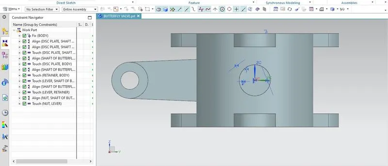
Step 1: Create a new assembly part file on the NX cad software then add all the components of Butterfly valve such as Lever, Nut, Retainer, Disc/plate, Body, Shaft on the assembly workbench.
Step 2: Now start giving the constraints to the components as:
- First we fix the body of valve by giving fix constraint.
- Then we use move component command to move disc plate near the shaft and align the axis of holes of shaft with the corresponding axis of holes. Then apply the touch contraints to fix the disc on the shaft.
- Now align the axis of shaft with the axis of body and use touch contraints between the inner surface of body and disc plate to close the cross- sectional area of the body.
- Then we align the axis of Retainer with the axis of shaft and use touch constraint to fix the retainer on the body.
- Then we place the lever on the top of retainer by aligning the axis of the larger cylinder in the lever with the shaft also we apply align constraint to one face of key cutout in lever with the face of key cutout in the shaft to ensure the placement of Key inside this cutout smoothly.
- Now we apply touch constraint to the lower surface of lever and retainer to fix the lever.
- Finally we align the axis of nut with axis of shaft na duse touch constraint in between the lower surface of nut and top surface of lever to fix the nut on top of lever.
- NOTE: We use move component command to move the component near other then apply the respective constraints as mentioned above.
So our final design will look like this:
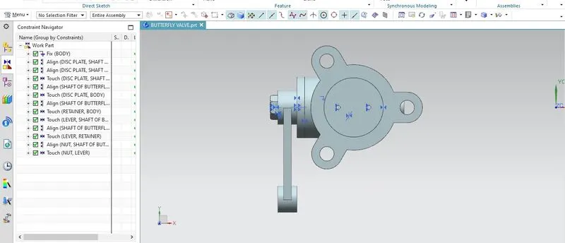
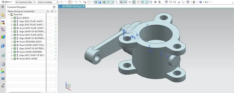
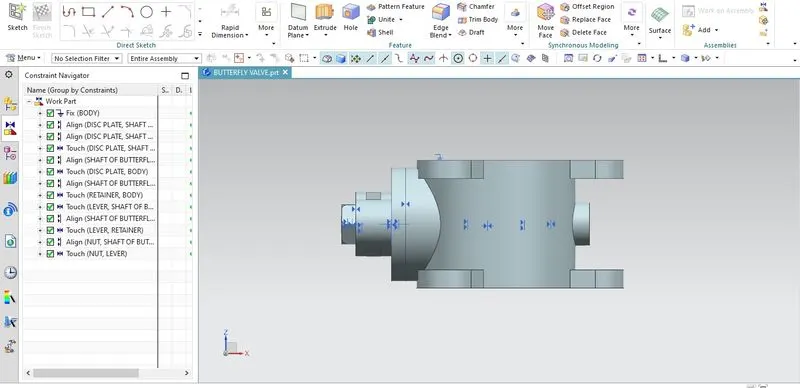
Step 3: Now apply GD and T on the above design, by using the drafting command on the NX CAD.
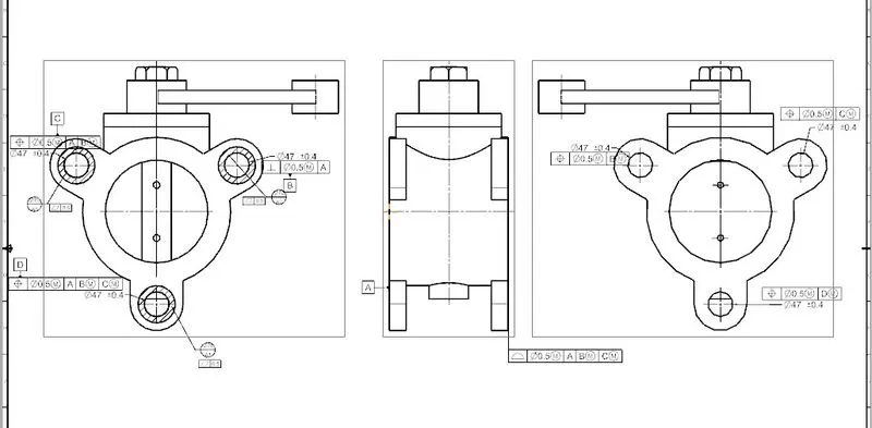
- We are taking top views and projected view to apply GDand T on the above constructed design.
- First fix the datum A to constraint the three degree of freedom of the design, for datum A we apply datum target area the dia is taken to be 70 mm for target area, in this way we create datum targets A1, A2 and A3 and apply flatness tolerance on these targrt areas.
- Now we apply the perpendicularity tolerance to one of the holes in referance to datum A at MMC, so in this way we fix the datum B and the two more degrees of freedom of design are restricted.
- Now we apply the postion tolerance to another hole in referance to datum A and datum B at MMC condtion for tolerance size as well as for the datum B, in this way our datum C has been created.
- Also we give the dimension tolerance to each hole.
- Then we give position tolerance to the remaining hole in reference to datum A, B and C at MMC conditon for tolerance size and datum B and C, By this we fix datum D the purposre for creating this datum is to fix the axis of hole opposite to its surface,
- Now we take opposite surface of design where the three ears with holes in it are present, now we fix these hole by giving position tolerance in referance to datum opposite to them, for instance we gave postion tolerance to on hole in referance to datum B at MMC which means it would fix the axis of that hole with the hole opposite to it, in similar way we gave postion tolerance to other two holes in referance to datum C and D respectively acc. to the hole opposite to them.
- Finally give the profile tolerance to the surface opposit to datum A in referance to datum A, B and C at MMC.
- So our final drawing will look like this: