Week 14 challenge
1.After creating a new file naming Butterfly assembly in the Assembly work environment.Load the Body at the origin and apply fix contraint for a reference to the other parts of the assembly.
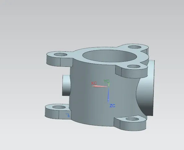
2.
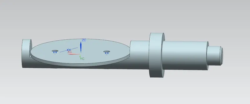
a)Load the shaft and disc plate in a scattering condition.
b)Move the disc plate in such a way that it comes parallel to the shaft's flat surface .
c)Apply align with the centre line contraint and select the centre lines of the holes of the plate and the shaft.
d)Apply touch Constraint between the lower portion of the plate and the upper part of the shaft flat surface ,so now the plate is fully constraint in the shaft.
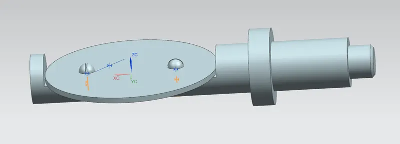
e) Load the small screw and move them closer to the plates hole axis.
f)Apply align with the centre line contraint and select the centre lines of the holes and the screws .
g)Apply touch constraint between the upper plate layer and the screw's lower flat surface.
3.
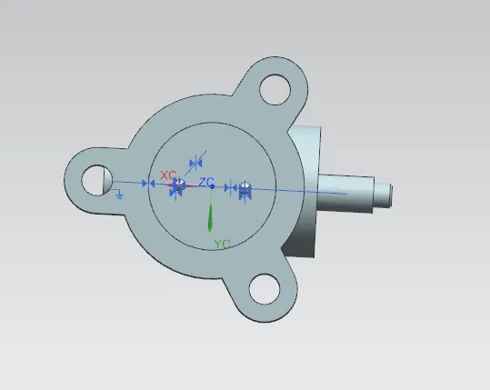
a)Align the upper prepared shaft & plate assembly with the centre line of the main hole.
b)Apply touch constraint to the disc plate side strip and the body inner surface .
4.Fixing the Retainer onto the body.
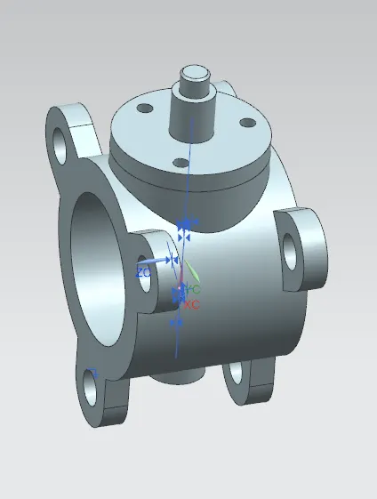
a)Load the retainer and apply align with centre line constraint between the three holes of body and the retainer.
b)apply touch constraint to fix the retainer onto the body.
5.Fixing the bigger screws into the body and retainer.
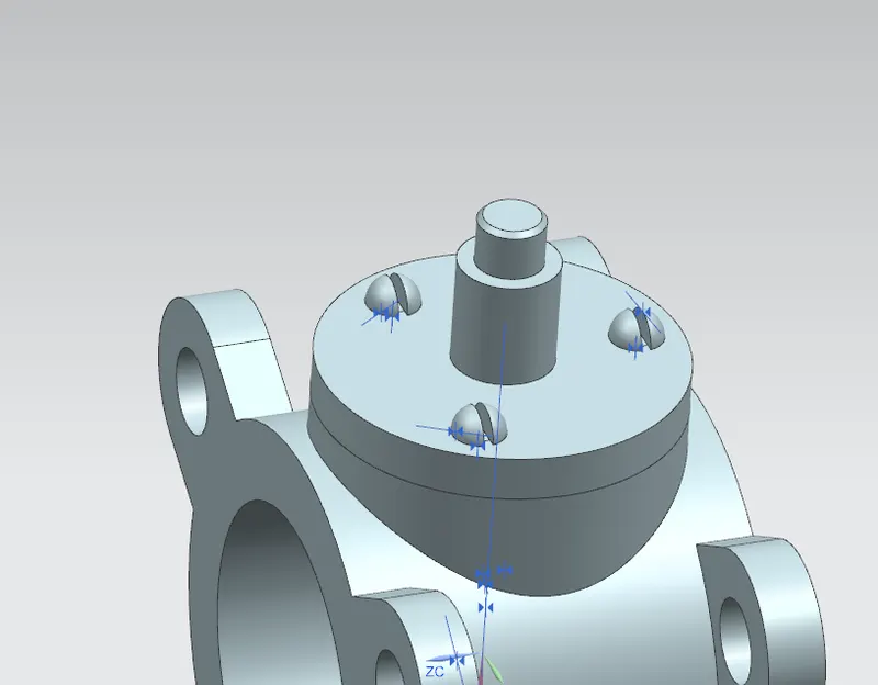
a)Load the bigger screw and move them closer to the plates hole axis.
b)Apply align with the centre line contraint and select the centre lines of the holes and the screws .
c)Apply touch constraint between the upper layer of retainer and the screw's lower flat surface.
6.Fixing of the handle
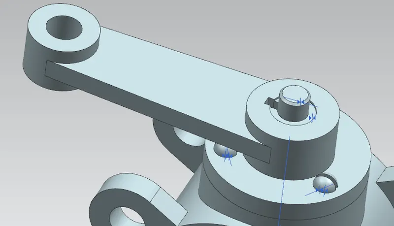
a)Load the handle and move it close to the assembly.
b)Apply align with centre line between the shaft and the bigger hole of the handle .
c) Apply align to the surfaces of the key ways of both shaft and handle.
d) Apply touch constraint to the lower surface of the handle and upper surface of the retainer.
7.Setting the final Nut at the top.
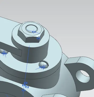
a) Load and align the centres of nut and the shaft .
b)Apply touch align to the bottom nut surface and the upper handle surface .
8.Drafting & gd&t
1.
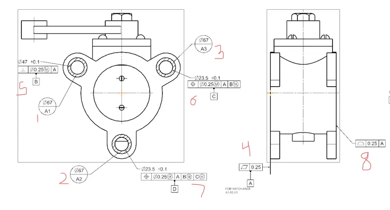
1. POINT 1-3 :- These are the Datum target areas A1,A2,A3 on the body as this part is going to touch the other assemblies.
2.POINT 4 :- this is Datum A surface consisting datum target areas A1,A2,A3 ,with Flatness 0.25 along the hatched areas.
3.POINT 5:- hole with the tolerance +-0.1 and the perpendicularity tolerance with dia 0.25mm with maximum material condition along the centre axis with reference to Datum A ,and this is named as Datum B.
4.POINT 6:- hole with the tolerance +-0.1 and the position tolerance with dia 0.25mm with maximum material condition along the centre axis with reference to Datum A,B with maximum material condition.This is Datum C.
5.POINT 7:-hole with the tolerance +-0.1 and the position tolerance with dia 0.25mm with maximum material condition along the centre axis with reference to Datum A,B with maximum material condition & C with maximum material condition .This is Sub datum D to give reference to the opposite side hole.
6.POINT 8:- Profile tolerance of 0.25mm with reference to datum A to maintain tight tolerance .
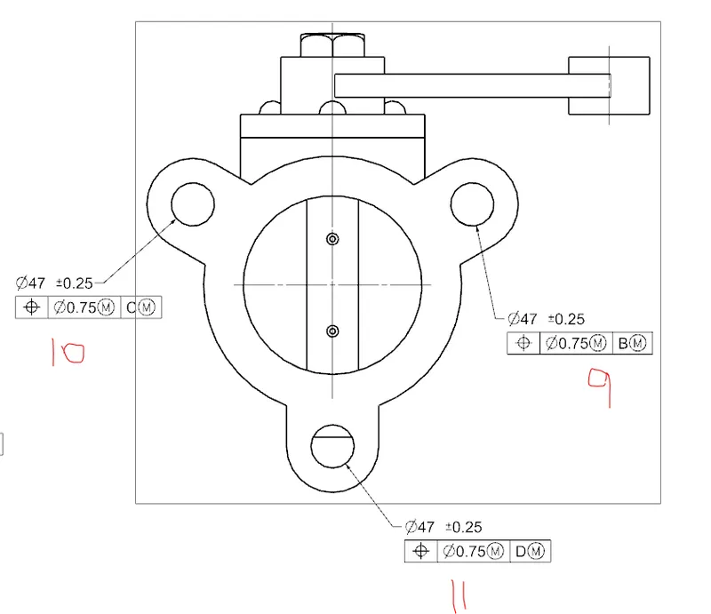
7.POINT 9:- Hole with the tolerance of +-0.25,Position tolerance of 0.75mm with maximum material condition with reference to Datum B with Maximum material condition.
8.POINT 10:- Hole with the tolerance of +-0.25,Position tolerance of 0.75mm with maximum material condition with reference to Datum C with Maximum material condition.
9.POINT 11:- Hole with the tolerance of +-0.25,Position tolerance of 0.75mm with maximum material condition with reference to Datum D with Maximum material condition.