Week 14 challenge
ASSEMBLE THE COMPONENTS OF A BUTTERFLY VALVE AND APPLYING GD&T TO THE ASSEMBLY DRAWING
Aim
The aim of the project is to assemble the various components of a butterfly valve and apply GD&T to the drawing to constraint sketch.
Introduction
A butterfly valve is a rotary motion valve that is used to stop, regulate, and start fluid flow. Butterfly valves are easily and quickly operated because a 90degree rotation of the handle moves the disk from a fully closed to fully opened position. Butterfly valves are especially well-suited for the handling of large flows of liquids or gases at relatively low pressures and for the handling of slurries or liquids with large amounts of suspended solids.
Butterfly valves are built on the principle of a pipe damper. The components of a butterfly valve are made up of seven main parts Body, stem/shaft, disc, retainer, nut, screw and lever.
The body of the butterfly valve is the part that fits between the two pipes. It is connected to the pipes with bolt holes that run through the body of the valve. This design is easy to install and primarily used to prevent backflow in universal flow systems.
The flow control element of a butterfly valves is a disk of approximately the same diameter as the inside diameter of the adjoining pipe, which rotates on either a vertical or horizontal axis. The disc has an interference fit with the seat in the closed position and the disk is bored through and secured to the stem with bolts or pins.
When the disk lies parallel to the piping run, the valve is fully opened. When the disk approaches the perpendicular position, the valve is shut. Intermediate positions, for throttling purposes, can be secured in place by handle-locking devices.
Steps followed
- Understand the drawing and noted the functional contact between various components of a butterfly valve.
- Adding all the components in to one single file by using assembly workbench in the NX.
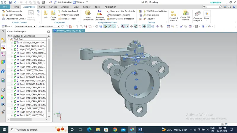
First the main body of the butterfly valve is fixed by using fix constraint
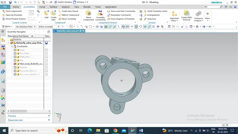
Assemble the disc with the shaft/stem by constraining the center axis of screw holes in the disc with the provision holes in the stem and by touch constraint between the mating surface.
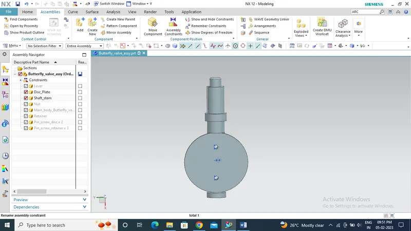
Insert screws/pins to the holes with reference to the central axis and by touch constraint
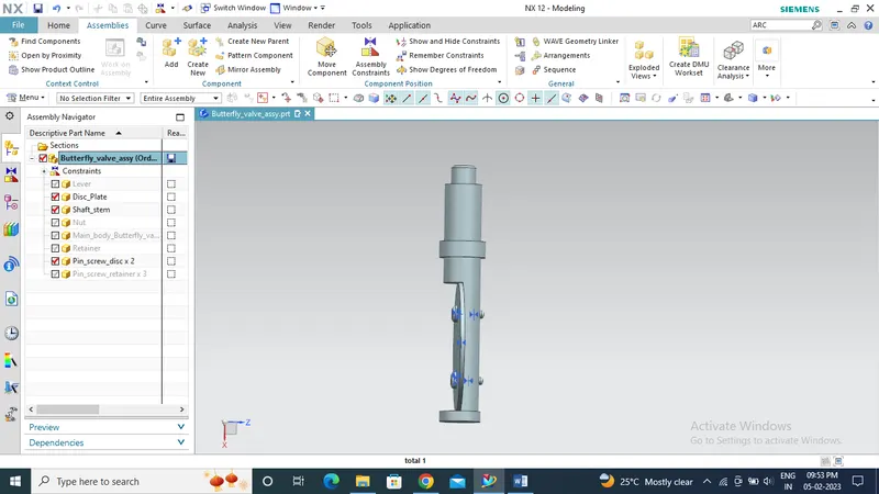
Bring the subassembly of shaft/stem and disc to the main body by aligning the center axis of both and applying touch constrain to the surface of disc with the inner surface of main body.
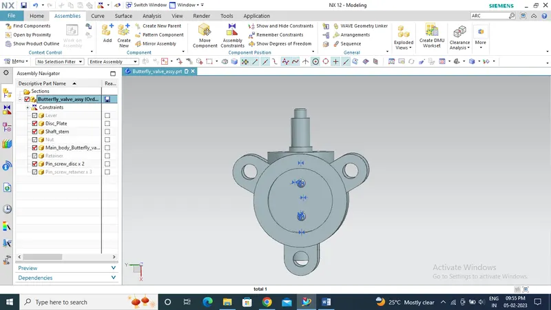
Retainer comes in a position with the main body by aligning the center axis and applying touch constraint between the surfaces.
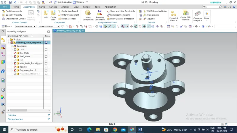
Insert the screw/holes for joining the retainer with the main body by aligning the center axis and touch constraint
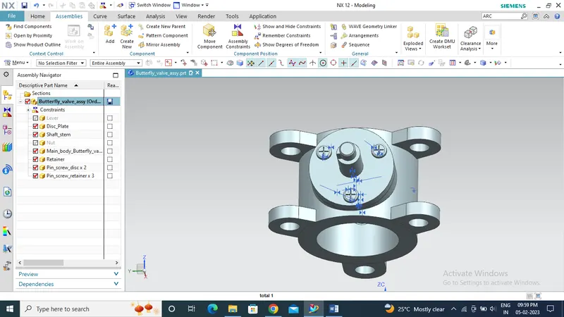
Now the Lever is constraint in such a way that the bigger hole with a slot in it with the shaft/stem by applying center axis and touch constraint
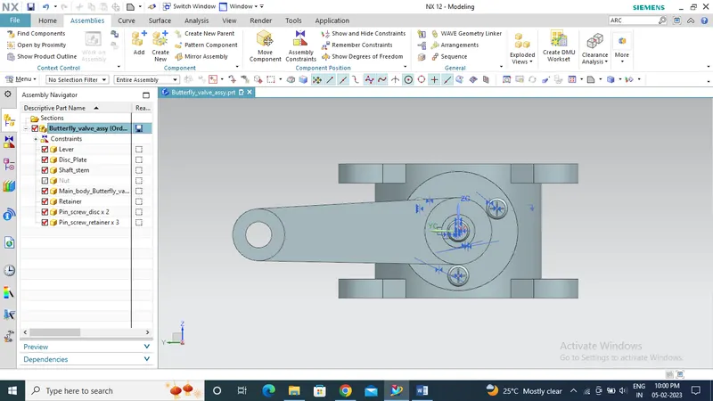
Finally, the nut is assembled to tighten the entire assembly by aligning the center axis and applying touch constraint with the shaft/stem of the butterfly valve
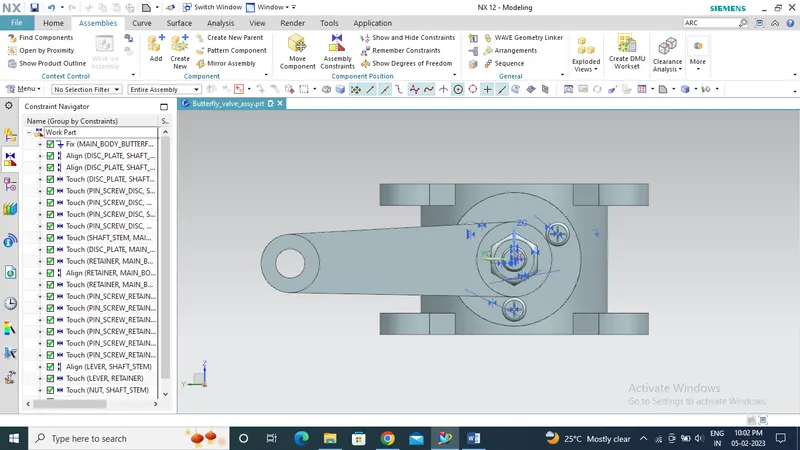
Fully constrained assembled butterfly valve
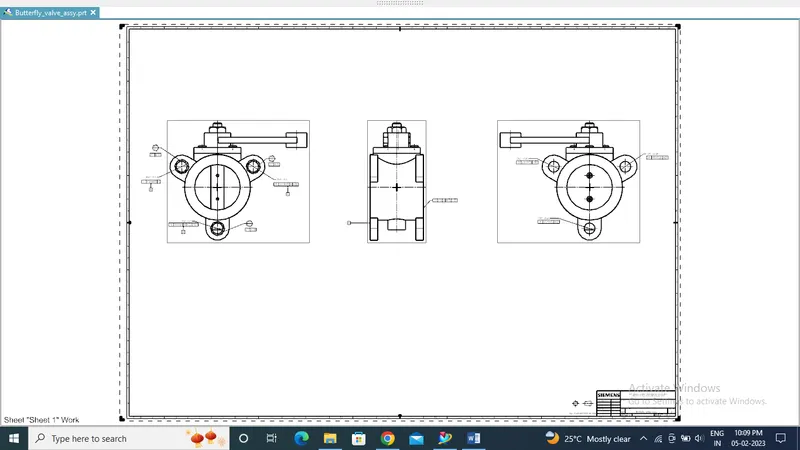
Applying GD&T to the assembly of Butterfly valve
- From the assembly we can understand that the body of the butterfly valve is the part that fits between the two pipes and thus control the fluid flow accordingly we need to apply GD&T and constraint the assembly of butterfly valve.
- By using drafting workbench in the NX software we can add base view to the drafting template and as well as the required projection views. GD&T symbols can be applied to the projected views in the drafting template by using various tool bars available in NX software.
- Identifying the primary, secondary and other datum points with respect to functional contact of the assembly and constraint them with respect to the mating parts
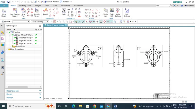
- The primary datum point will be the surface which is going to be in contact with the external pipes which can be controlled by defining three datum target area around the holes and flatness tolerance is applied to the them.
- A nominal diameter shape tolerance is applied to the holes
- One of the hole inside the datum target area ‘A’ will be the secondary datum point B. Perpendicularity tolerance is applied with reference to the datum target point ‘A’.
- Tertiary datum target point will be the either one of the balance two holes and a position tolerance is applied to it with reference to the datum target point ‘A’ and ‘B’.
- And for the third hole we will provide a position tolerance with respect to the datum points A,B,C and this will our fourth datum target point.
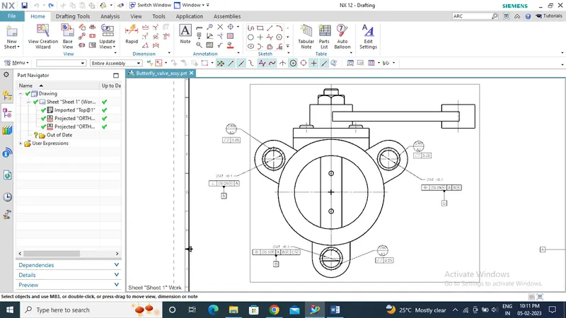
- A tight surface profile tolerance is applied to the opposite side of datum target point ‘A’ thus we are constraining the opposite surface.
- All the holes in the opposite side should be in coaxial with respect to the respective datum target points so we have applied a position tolerance to it and constrained the entire assembly.
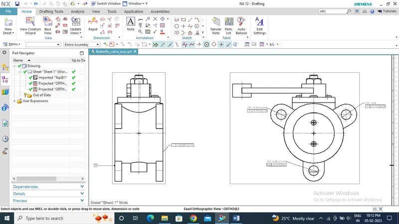
Fully constraint GD&T sketch
Conclusion
Thus we have successfully constraint and assembled the various parts and features of butterfly valve and applied GD&T.