Week 14 challenge
AIM:
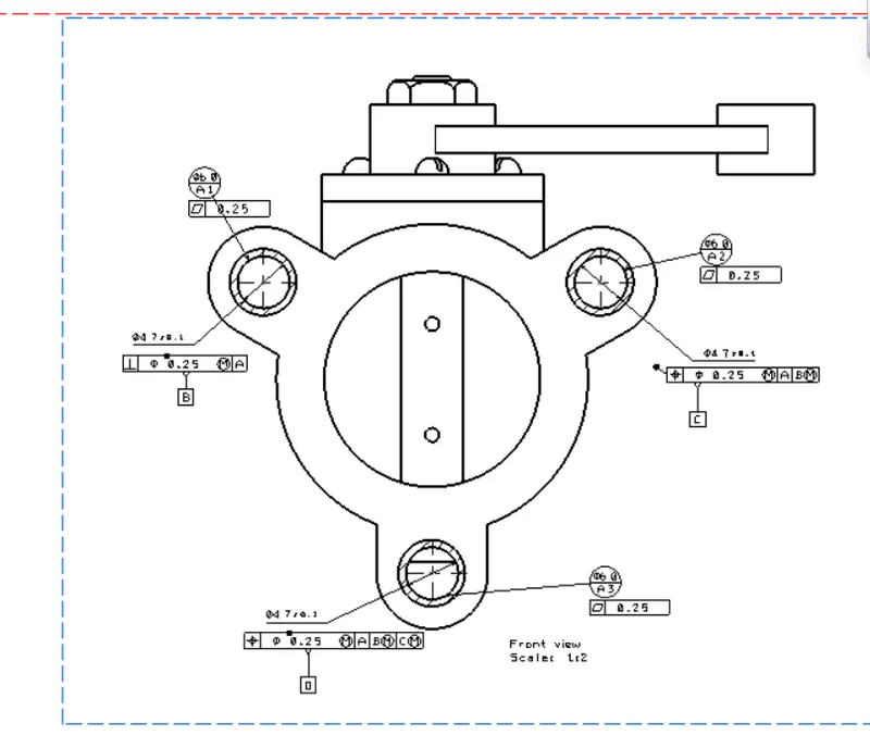
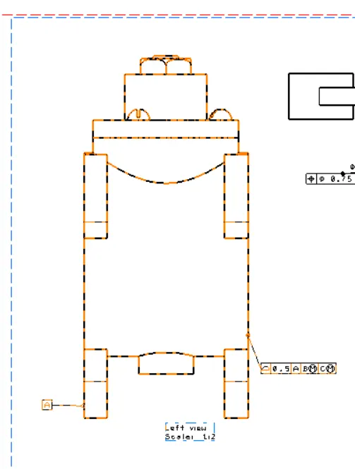
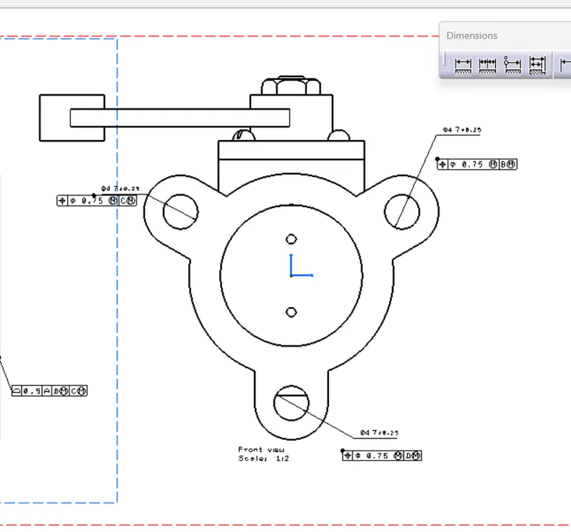
To design a butterfly valve and apply to apply GD&T symbols to the drawing and finally to apply all the parts in the butterfly valve to make it as one assembly file and the assembly consist of all the parts. this process are done by using CATIA V5.
DESIGNING SOFTWARE:
CATIA V5
INTRODUCTION:
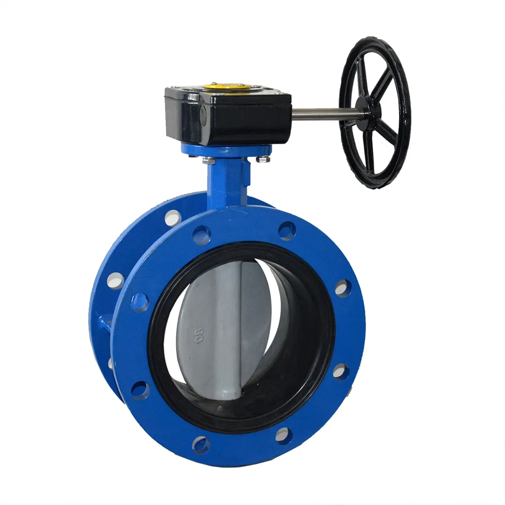
A butterfly valve is from a family of valves called quarter-turn valves. In operation, the valve is fully open or closed when the disc is rotated a quarter turn. The "butterfly" is a metal disc mounted on a rod. When the valve is closed, the disc is turned so that it completely blocks off the passageway.Butterfly valves are used where space is limited. Unlike gate valves, butterfly valves can be used for throttling or regulating flow as well as in the full open and fully closed position. The pressure loss through a butterfly valve is small in comparison with the gate valve.Butterfly valves are often distinguished by the three main types: zero, double, or triple offset.There are several standards available worldwide that describe the symbols and define the rules used in GD&T. One such standard is American Society of Mechanical Engineers (ASME) Y14.5. This article is based on that standard, but other standards, such as those from the International Organization for Standardization (ISO), may vary slightly. The Y14.5 standard has the advantage of providing a fairly complete set of standards for GD&T in one document. The ISO standards, in comparison, typically only address a single topic at a time.
COMPONENTS ARE IN THE BUTTERFLY VALVE:
- BODY
- SHAFT
- RETAINER
- DISC PLATE
- LEVER HANDLE
- NUT
BODY:
The one of the major component in butterfly valve is body that is fit between two pipe flanges.
(1)
Create a 2D sketch of outerbody of butterfly valve using given diamention
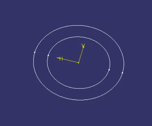
then pad it for the given Diamention
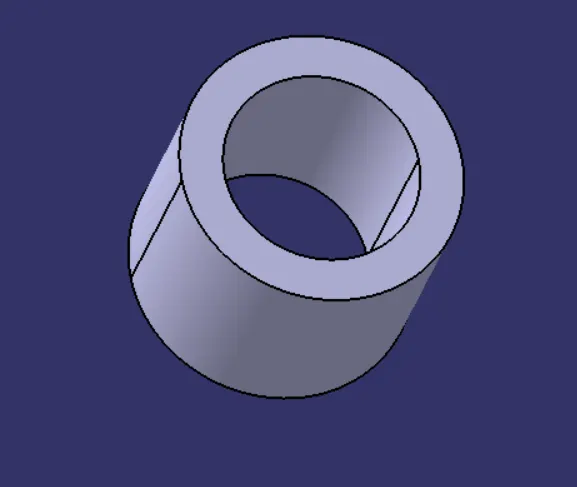
now we need to create the 3 circular flange holes to it
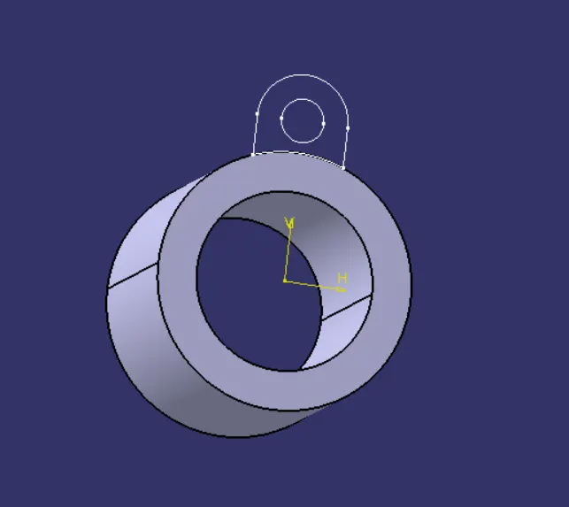
now we need to pad it in right direction
and also we need circular pattern of it 3 at 120 degree apart of each other and also we need to mirror att solid body in right plane
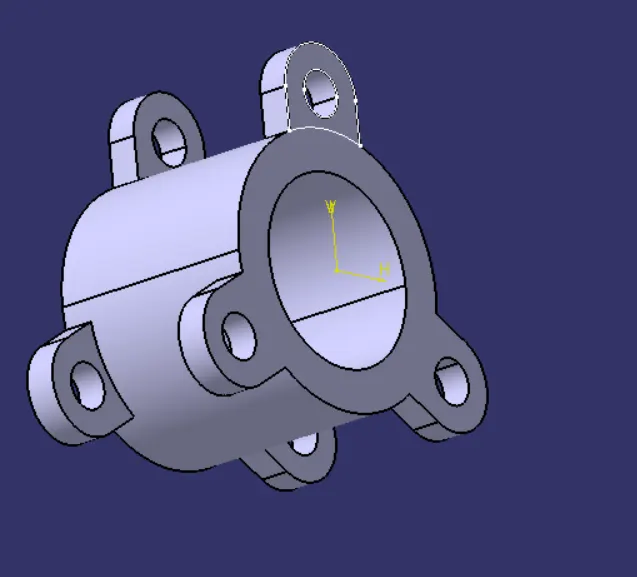
now we need to create one small pocket and other big pocket
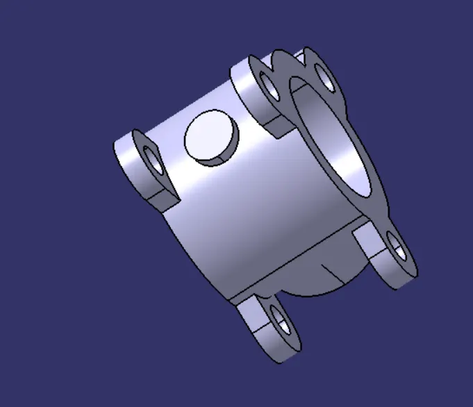
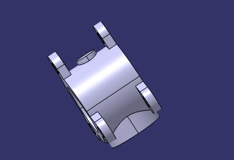
now we need yo make holes in it with given diamention and also need to Union trim it to make whole body as one body
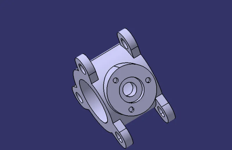
our final component is
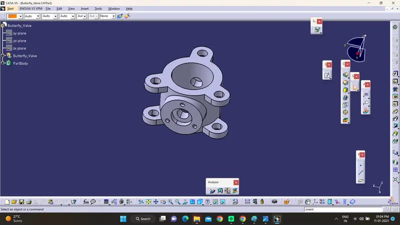
(2)
SHAFT
Design Shaft of Butterfly Valve Using Software CATIA V5
Procedure =
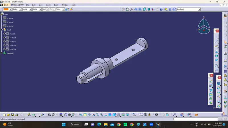
here from given diamention we need to draw a sketch of shaft

then with given diamention we need to shaft it using shaft command
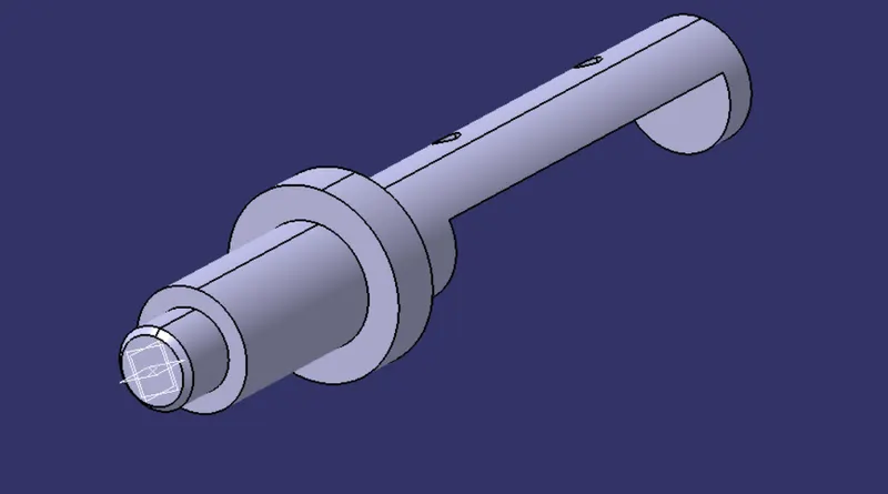
then with given command we need to make slot in it and also need to make holes in it
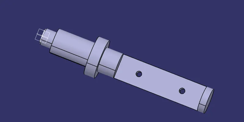
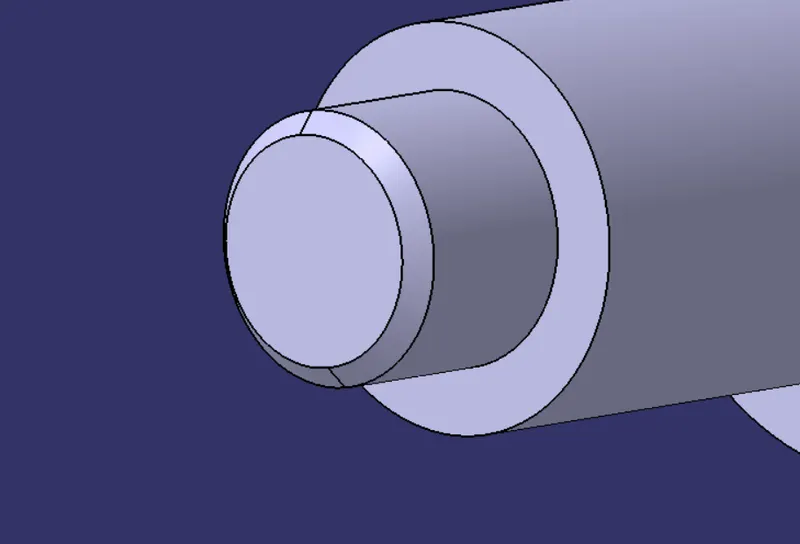
after that we need to make chamfer to the entry of shaft of given diamention
then we need to make slot in it with given diamention
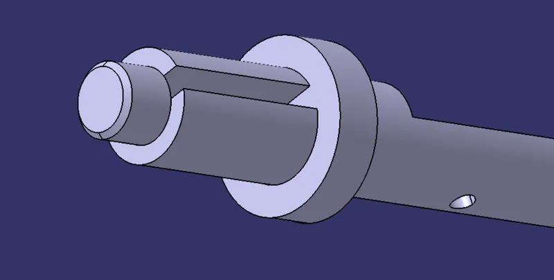
now our shaft body is ready...
(final component)
(3)
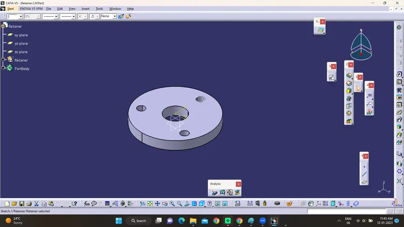
RETAINER
To create 3D solide body of retainer of butterfly valve using software CATIA V5
PROCEDURe =
we need to create sketch of given diamentions
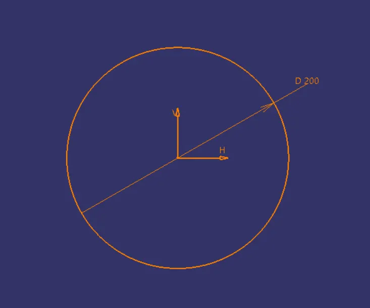
then we need to pad it for given diamentions
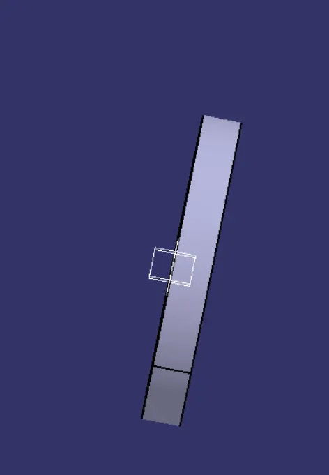
the we need to make pocket in it with given diamentions
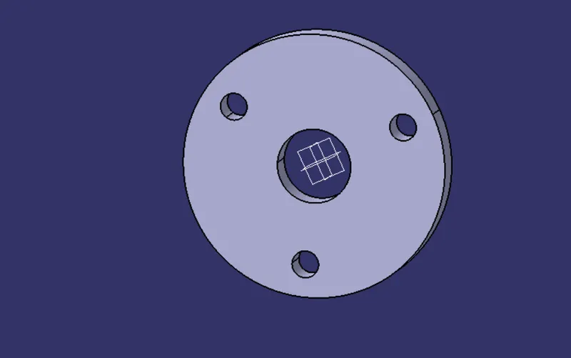
and also need to circulate pattern the pocket with 120 degree apart from each other and the defination of 1st pocket is need to draw 150 BCD in sketch
the our final component is ready
(4)
DISC
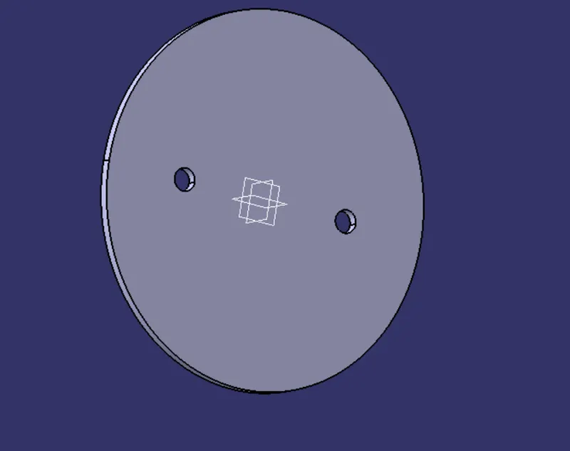
to create disc plate of butterfly valve using software CATIA V5
PROCEDURE =
we need to create sketch of given diamentions
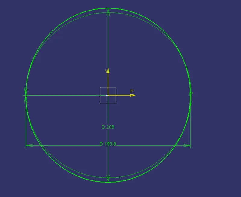
noe we need to pad it with given diamentions

now we need to make holes in it with given diamentions
(5)
HANDLE
to create 3D solid body of handle usinmg software CATUIA V5
PROCEDURE =
create a sketch of given diamention
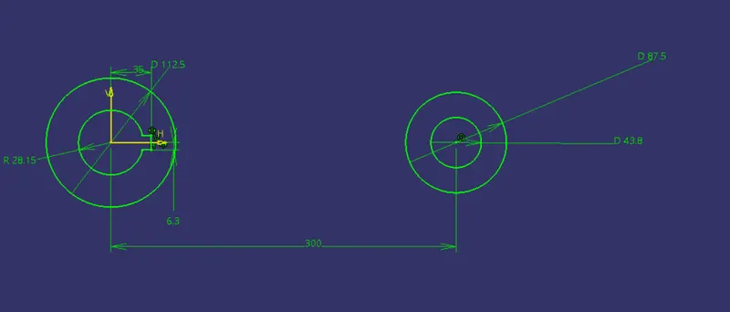
now we need to pad it for given diamention
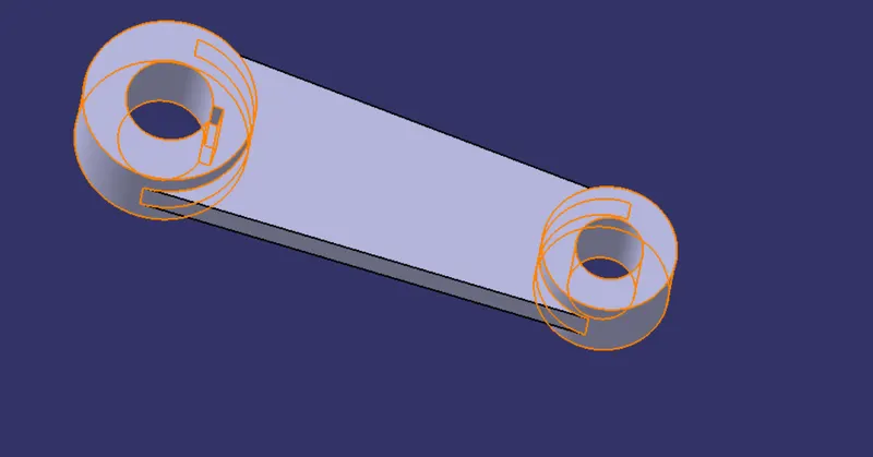
now our final component is
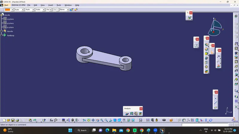
(6)
NUT AND SCREW
to create Nut solide body using software CATIA V5
PROCEDURE =
creatre a sketch of given diamention
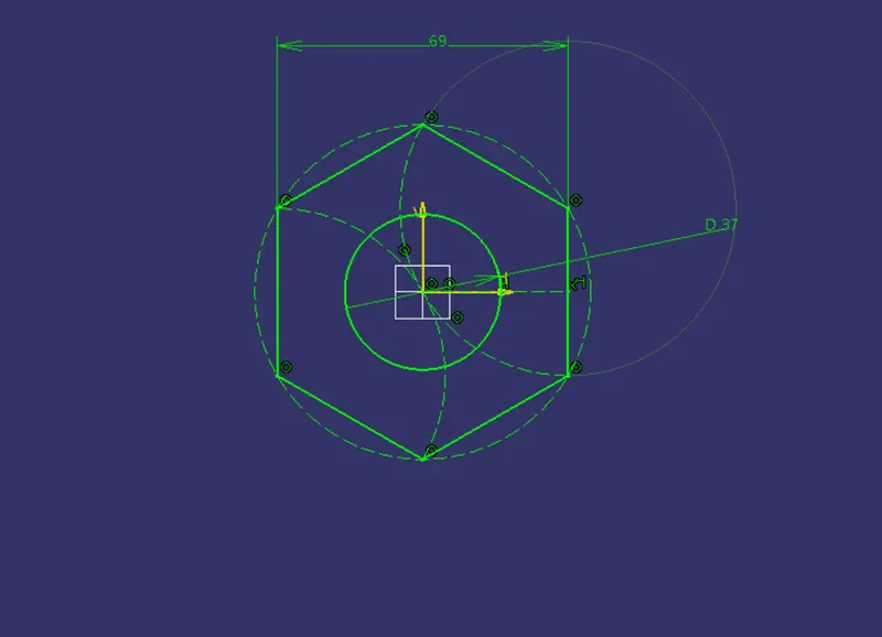
now we need to pad it with given diamention
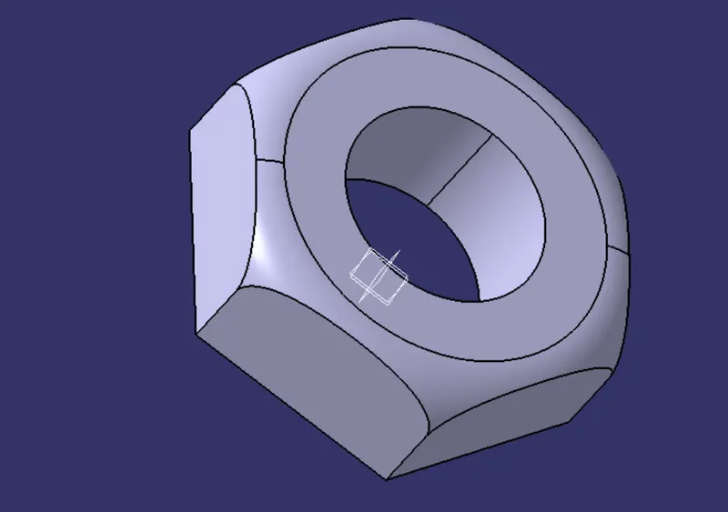
our final component is

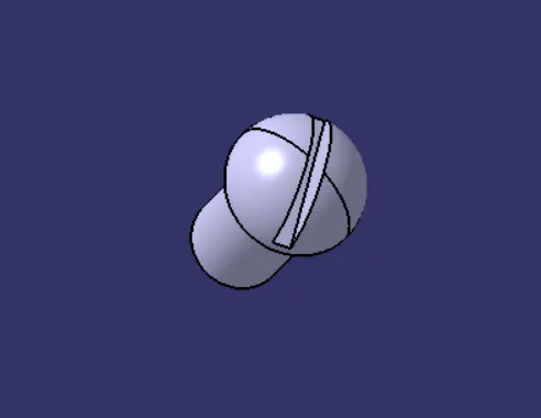
NOW WE NEED TO ASSEMBLE ALL COMPONENTS TOGETHER TO MAKE WHOLE ASSEMBLY...
ASSEMBLY
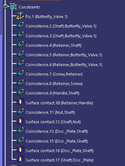
- Align the center axis of holes in disc and shaft
- provide touch constrain to face of shaft and bottomface of disc
- Align the center axis of screw and center axis of disc
- provide touch constrain to inside face of screw and inside face of disc
- disc is assembled with shaft
- Align the center axis of shaft and center axis of body
- provide touch constrain to inside face of body and side face of disc
- shaft is assembled inside body
- Align the center axis of holes in retainer and body
- provide touch constrain to bottom face of retainer and body
- Align the center axis of screw and center axis of hole in retainer
- provide touch constrain to inside face of screw and face of retainer
- retainer is assembled in body
- Align the center axis of hole in lever and shaft
- Align the edge of slot in lever and slot in shaft
- handle is assembled
- Align the center axis of nut and shaft
- provide touch constrain to bottom face of nut and retainer
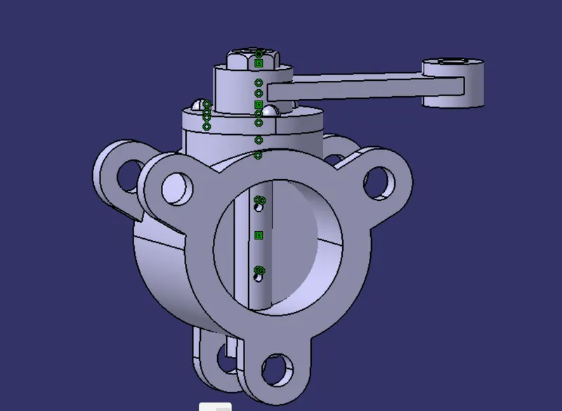
BUTTERFLY VAVLE ASSEMBLY IS CREATED
CONSTRAINTS I USED IN ASSEMBLY
BEFORE ASSEMBLE
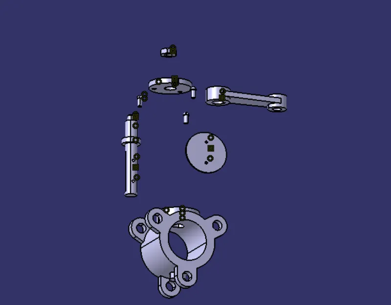
AFTER ASSEMBLE
ALSO WE CREATED SPECIFIC TOLERANCE TO WHOLE ASSEMBLY