Validation studies of Symmetry vs Wedge in Open FOAM vs Analytical H.P equation
AIM:
The aim of this project is to simulate the fully developed Hagen Poiseuille’s flow (Re = 2100) through a circular pipe and compare the effect of the type of boundary used in the solution obtained.
PROCEDURE:
The assumptions for Hagen Poiseuille equations are to be considered here as well. Referenced from FM white’s fluid mechanics. Le = 0.06 x Re x D. Where D is the diameter of the pipe.
Le = 0.06 x 2100 x 0.01
Le = 1.26m
The hydrodynamic entrance length is the length of the pipe through which a fluid travels before becoming a fully developed flow. The flow would have the velocity profile as shown.
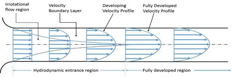
The above picture is taken from a Wikipedia article.
We assume that the pipe length is greater than the hydrodynamic entrance length. Lippe = 1.5 m
And since the fluid inside the pipe is water, we take the properties of water at NTP
C and 1atm
Density `rho=998frac{kg}{m^3}`
Dynamic Viscosity `mu=0.00089frac{Ns}{m^2}`
Kinematic Viscosity `nu = 1.005e-6 m^2/s`
`V_{avg}=frac{Re. mu}{rho.D}`= 0.187 m/s
`V_{max}=2.V_{avg}`= 0.374 m/s
`Delta P=frac{8.mu.L.V_{avg}}{r^2}` = 101.583 pa
`DeltaP_k=frac{Delta P}{rho}`= 0.101 (m/s) ^2
`tau=mu.frac{dx}{dy}`
We use the post-processing software i.e., Para View to plot shear stress graph
In the blockmeshdict file, we change the type to symmetry from wedge.
blockmeshdict file
/*--------------------------------*- C++ -*----------------------------------*
  =========                |
        /  F ield         | OpenFOAM: The Open Source CFD Toolbox
       /   O peration     | Website:  https://openfoam.org
      /    A nd           | Version:  8
     /     M anipulation  |
/*---------------------------------------------------------------------------*/
FoamFile
{
    version     2.0;
    format      ascii;
    class       dictionary;
    object      blockMeshDict;
}
// * * * * * * * * * * * * * * * * * * * * * * * * * * * * * * * * * * * * * //

convertToMeters 1;

vertices
(
	(0 0 0)//0
	(0.004981 0.000436 0)//1
	(0.004981 -0.000436 0)//2
	(0 0 1.500000)//3
	(0.004981 0.000436 1.500000)//4
	(0.004981 -0.000436 1.500000)//5
);


blocks
(
	 hex (0 2 1 0 3 5 4 3) (30 1 300)simpleGrading(0.2 1 1)
);

edges
(
	 arc 1 2 (0.005000 0 0)
	 arc 4 5 (0.005000 0 1.500000)
);

boundary
(
	inlet
	{
		 type patch;
		 faces
		 (
			(0 2 1 0)
		 );
	}
	outlet
	{
		 type patch;
		 faces
		 (
			(3 5 4 3)
		 );
	}
	top
	{
		 type wall;
		 faces
		 (
			(2 1 4 5)
		 );
	}
	front
	{
		 type symmetry;
		 faces
		 (
			(0 3 4 1)
		 );
	}
	back
	{
		 type symmetry;
		 faces
		 (
			(0 2 5 3)
		 );
	}
	axis
	{
		 type empty;
		 faces
		 (
			(0 3 3 0)
		 );
	}
);

mergePatchPairs
(
);

// ************************************************************************* //
The controlDict file should look something like this
/*--------------------------------*- C++ -*----------------------------------*
  =========                 |
        /  F ield         | OpenFOAM: The Open Source CFD Toolbox
       /   O peration     | Website:  https://openfoam.org
      /    A nd           | Version:  8
     /     M anipulation  |
*---------------------------------------------------------------------------*/
FoamFile
{
    version     2.0;
    format      ascii;
    class       dictionary;
    location    "system";
    object      controlDict;
}
// * * * * * * * * * * * * * * * * * * * * * * * * * * * * * * * * * * * * * //

application     icoFoam;

startFrom       startTime;

startTime       0;

stopAt          endTime;

endTime         10;

deltaT          0.001;

writeControl    timeStep;

writeInterval   20;

purgeWrite      0;

writeFormat     ascii;

writePrecision  6;

writeCompression off;

timeFormat      general;

timePrecision   6;

runTimeModifiable true;


// ************************************************************************* //
Now we need to set up the initial conditions, we make the same changes as we did in blockmeshdict here as well.
Once coded the files should look like this
Pressure
/*--------------------------------*- C++ -*----------------------------------*
  =========                 |
        /  F ield         | OpenFOAM: The Open Source CFD Toolbox
       /   O peration     | Website:  https://openfoam.org
      /    A nd           | Version:  8
     /     M anipulation  |
*---------------------------------------------------------------------------*/
FoamFile
{
    version     2.0;
    format      ascii;
    class       volScalarField;
    object      p;
}
// * * * * * * * * * * * * * * * * * * * * * * * * * * * * * * * * * * * * * //

dimensions      [0 2 -2 0 0 0 0];

internalField   uniform 0;

boundaryField
{
    inlet
    {
        type            zeroGradient;
    }

    outlet
    {
        type            fixedValue;
        value           uniform 0.0800;
    }

    axis
    {
        type            empty;
    }

    top
    {
        type            zeroGradient;
    }

    front
    {
        type            symmetry;
    }

    back
    {
        type            symmetry;
    }
}

// ************************************************************************* //
Velocity
/*--------------------------------*- C++ -*----------------------------------*
  =========                 |
        /  F ield         | OpenFOAM: The Open Source CFD Toolbox
       /   O peration     | Website:  https://openfoam.org
      /    A nd           | Version:  8
     /     M anipulation  |
*---------------------------------------------------------------------------*/
FoamFile
{
    version     2.0;
    format      ascii;
    class       volVectorField;
    object      U;
}
// * * * * * * * * * * * * * * * * * * * * * * * * * * * * * * * * * * * * * //

dimensions      [0 1 -1 0 0 0 0];

internalField   uniform (0 0 0.1874);

boundaryField
{
    inlet
    {
        type            fixedValue;
        value           uniform (0 0 0.1874);
    }

    outlet
    {
        type            zeroGradient;
    }

    axis
    {
        type            empty;
    }

    top
    {
        type            fixedValue;
        value           uniform (0 0 0);
    }

    front
    {
        type            symmetry;
    }

    back
    {
        type            symmetry;
    }
}

// ************************************************************************* //
To specify the type of fluid flowing inside the pipe we edit the transport properties file in the constant folder. In the transport properties file, we edit the nu value using a standard text editor and set it to 1.005e-6 m^2/s. Once edited the transport properties file should look like this.
/*--------------------------------*- C++ -*----------------------------------*
  =========                 |
        /  F ield         | OpenFOAM: The Open Source CFD Toolbox
       /   O peration     | Website:  https://openfoam.org
      /    A nd           | Version:  8
     /     M anipulation  |
*---------------------------------------------------------------------------*/
FoamFile
{
    version     2.0;
    format      ascii;
    class       dictionary;
    location    "constant";
    object      transportProperties;
}
// * * * * * * * * * * * * * * * * * * * * * * * * * * * * * * * * * * * * * //

nu              [0 2 -1 0 0 0 0] 1.005e-6;


// ************************************************************************* //
Now we run the following commands in the terminal
$blockMesh
$checkMesh (not required mostly but just to be sure)
$icoFoam
$paraFoam
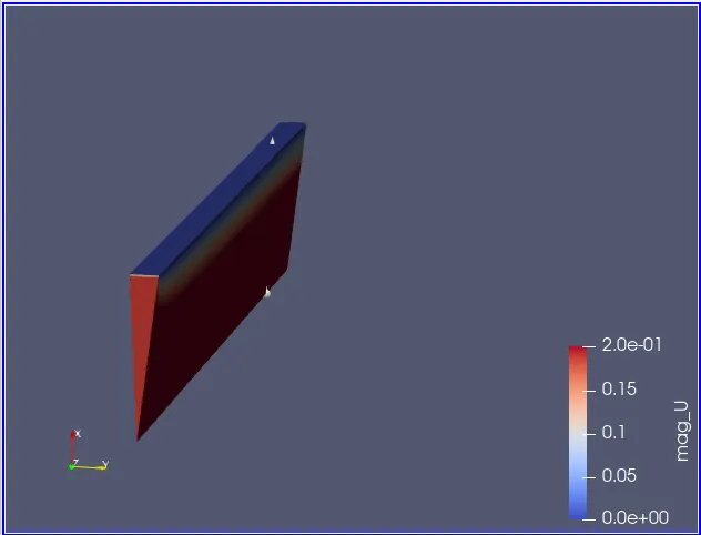
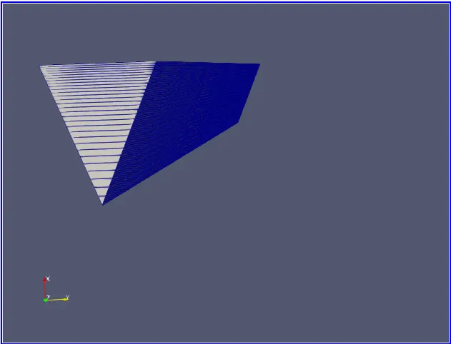
In the Paraview once our geometry is loaded it should look like this.
10 degree 25 degree
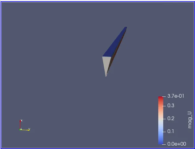
45 degree
After running the simulation, the velocity profile would look like this. We used the plot over line tool in Para view to plot at the required location.
10 degree
symmetry wedge
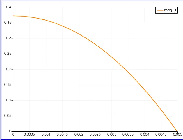
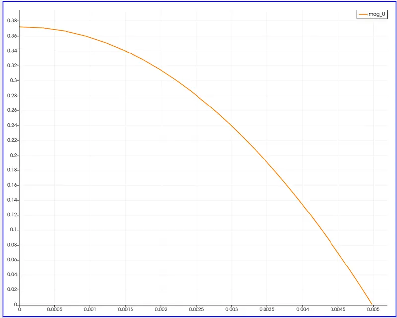
25 degree
symmetry wedge
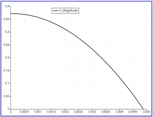
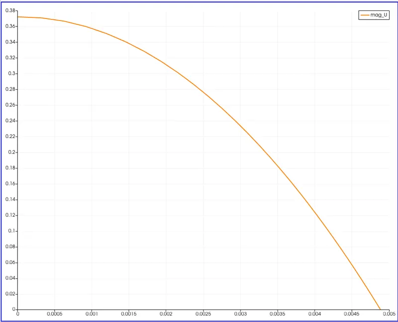
45 degree
symmetry wedge
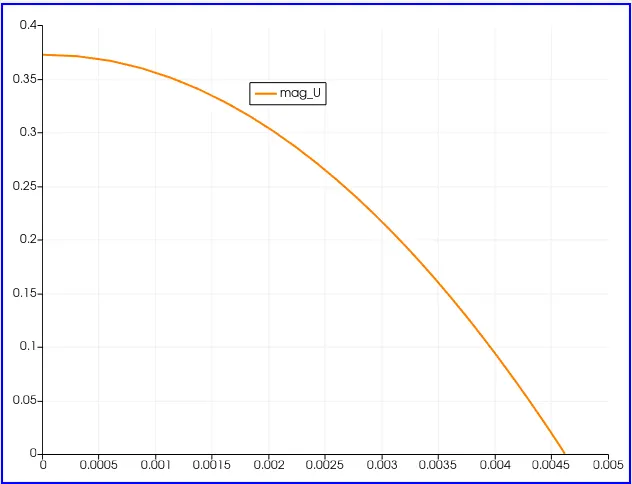
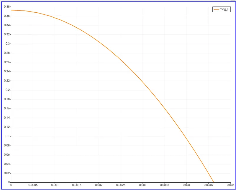
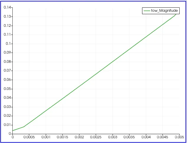
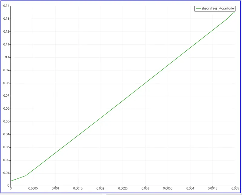
To calculate the shear stress, we use the calculator tool in paraview to calculate the gradients and then multiply the gradients with mu to get the shear stress. The generated shear stress plot would look like this.
10 degree
symmetry wedge
25 degree
symmetry wedge
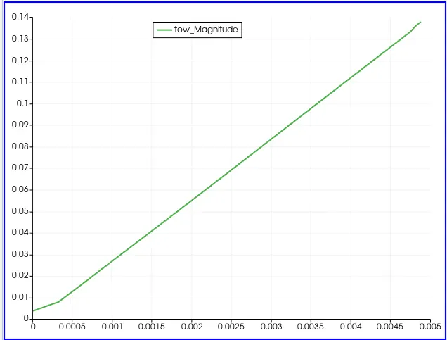
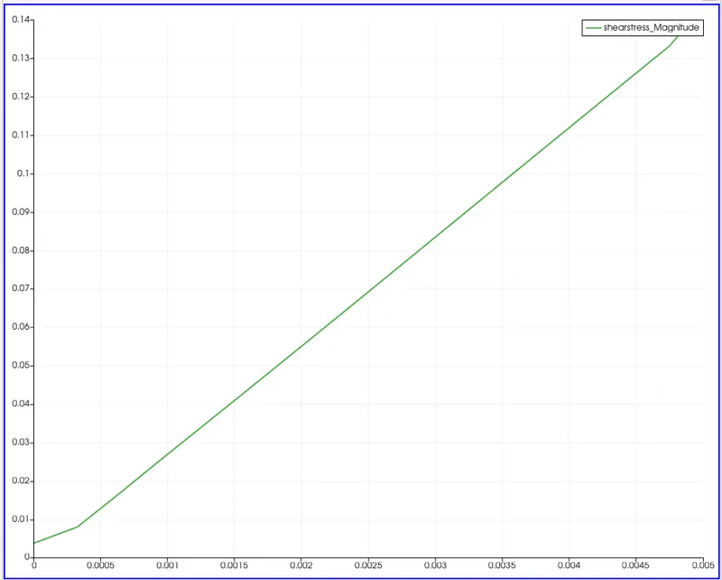
45 degree
symmetry wedge
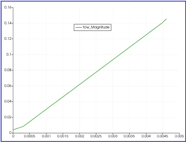
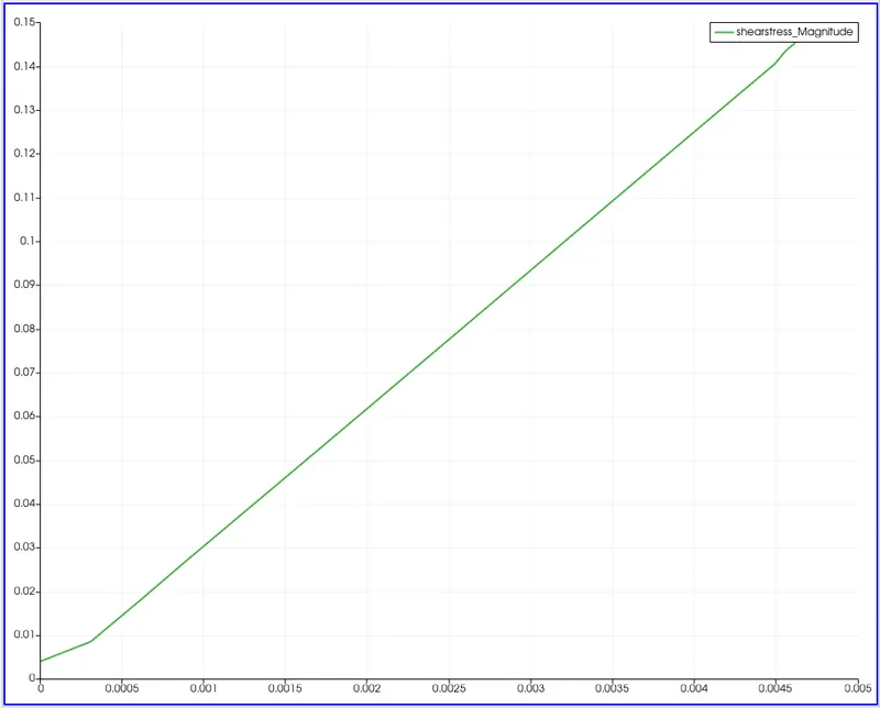
CONCLUSION.
The results obtained are as follows
10 degree
| Parameters | Symmetry | Wedge | Analytical HP equation solution |
| Velocity (max) | 0.371963 | 0.371963 | 0.374m/s |
| shear stress (max) | 0.135149 | 0.13539 | 0.135 N/m2 |
25 degree
| Parameters | Symmetry | Wedge | Analytical HP equation solution |
| Velocity (max) | 0.372234 | 0.372233 | 0.374m/s |
| shear stress (max) | 0.137835 | 0.137835 | 0.135 N/m2 |
45 degree
| Parameters | Symmetry | Wedge | Analytical HP equation solution |
| Velocity (max) | 0.372795 | 0.372795 | 0.374m/s |
| shear stress (max) | 0.145382 | 0.145382 | 0.135 N/m2 |
- From the above results, we can say that the results obtained for both wedge type and symmetry type do not have much difference between them and they comply with the analytical solution.
- Also, both the conditions seem to be grid-independent. While execution time changes with the grid size, it is also observed that on running both the conditions in OpenFOAM, the execution time needed for the symmetry condition is more than the wedge condition.