Week 12 - Validation studies of Symmetry BC vs Wedge BC in OpenFOAM vs Analytical H.P equation
Aim & Objective:
Note: This challenge is a continuation of the week 11 challenge.
In this challenge you will simulate the same problem as in week 1 but by applying Symmetry Boundary Condition. You will do the simulation for the below mentioned angles using both symmetry and wedge boundary conditions and validate them with HP equations like you did in week 11 challenge.
Angles to test:
- 10 degree
- 25 degree
- 45 degree
Expected Results
- Validate Hydro-dynamic length with the numerical result
- Validate the fully developed flow velocity profile with its analytical profile
- Validate maximum velocity and pressured drop for fully developed flow
- Post-process Shear stress and validate wall shear stress for fully developed flow
- Highligh the differences in both boundary conditions in terms of their usage and aplication
Answer:
In this project, the boundary condition needs to change for the front & back faces mentioned in the blockMeshDict dictionary file & also in U & p dictionary files for the same faces and the wedge angle is required to change from 5 degree to 10, 25 & 45 degree respectively for each new case.
The simulation time is the only change made in this simulation apart from the BC & wedge angle. The week 11 challenge was ran for 60 seconds with 0.001 time step size while the week 12 challenge was simulate for only 40 seconds because of limitation of computational power.
As the blockMeshDict file has been creaed using Octave software, the code was changed to create new boundary condition and also to change wedge angle to 10 degree. The code written in the Octave is displayed in the below attachment. Similar code was also written for 25 & 45 degree wedge angle case.
Main Code:
% Module - Introduction to CFD using MATLAB & OpenFOAM
% Challenge Week 11 - Simulation of Flow through a pipe in OpenFoam

% Author - Kartik Mehta
% Date - 3/10/2021

% The aim is to simulate laminar & incompressible flow in the circular pipe.
% This code will be used to generate blockMeshDict file in OpenFOAM to perform
% simualtion.
% OpenFOAM Solver - icoFOAM
% Fluid - Water

close all
clear all
clc

% Inputs
Re = 2100; % Reynolds Number

% Fluid properties
rho = 1000; % Density (kg/m^3)
mu = 8.9e-04; % Dynamic Viscosity (Pa.sec)
nu = mu/rho; % Kinematic Viscosity (m^2/s)

% Pipe dimensions
D = 0.01; % Pipe diameter (m)
Radius = D/2; % Radius of pipe (m)
Ac = (pi/4)*D^2; % Cross Section area of the pipe (m^2)
p_w = D*pi; % Wetted Perimeter(m)
Dh = 4*Ac/p_w; % Hydraulic Diameter(m)
rh = Dh/2; % Hydraulic Radius of pipe(m)

% Average Inlet velocity(m/s)
v_avg = (Re * mu)/(rho*Dh);

% Maximum velocity(m/s)
v_max = v_avg*2;

% Maximum shear stress
tau_max = (2*mu*v_max)/rh;

% Entracne Length of the pipe(m)
Le = 0.06*Re*Dh;

% Length of pipe(m)
L = Le + 0.18;

% Calculating Pressure Loss using Haigen Poiseulle's Equation
p_loss = (32*mu*(L-Le)*v_avg)/D^2;
head_loss = p_loss/(rho*9.81); % head loss
p_kinematic = p_loss/(rho*9.81); % Kinematic Pressure (psi)

% Wedge angle
angle = 10; % in degrees

% Printing variables in the command window
fprintf("Kinematic Viscosity = %d m^2/s\n", nu)
fprintf("Length of Pipe = %d m\n", L)
fprintf("Maximum Velocity = %d m/s\n", v_max)
fprintf("Kinematic Pressure = %d psi \n", p_kinematic)

% blockMeshDict header

l1 = '/*--------------------------------*- C++ -*----------------------------------*\';
l2 = '  =========                 |';
l3 = '  \\      /  F ield         | OpenFOAM: The Open Source CFD Toolbox';
l4 = '   \\    /   O peration     | Website:  https://openfoam.org';
l5 = '    \\  /    A nd           | Version:  8';
l6 = '     \\/     M anipulation  |';
l7 = '\*---------------------------------------------------------------------------*/';
l8 = 'FoamFile';
l9 = '{';
l10 = '    version     2.0;';
l11 = '    format      ascii;';
l12 = '    class       dictionary;';
l13 = '    object      blockMeshDict;';
l14 = '}';
l15 = '// * * * * * * * * * * * * * * * * * * * * * * * * * * * * * * * * * * * * * //';

% Creating file to write code
file = fopen('blockMeshDict.txt','wt');

% Writing first l1 tp l15 lines into text file
fprintf(file, '%s\n', l1);
fprintf(file, '%s\n', l2);
fprintf(file, '%s\n', l3);
fprintf(file, '%s\n', l4);
fprintf(file, '%s\n', l5);
fprintf(file, '%s\n', l6);
fprintf(file, '%s\n', l7);
fprintf(file, '%s\n', l8);
fprintf(file, '%s\n', l9);
fprintf(file, '%s\n', l10);
fprintf(file, '%s\n', l11);
fprintf(file, '%s\n', l12);
fprintf(file, '%s\n', l13);
fprintf(file, '%s\n', l14);
fprintf(file, '%s\n', l15);
fprintf(file, '\n');

% Unit Conversion
l16 = 'convertToMeters 1;';

% Vertices Header
l17 = 'vertices';
l18 = '(';

% Vertices
v_0 = [0 0 0];
v_1 = [rh*sind(angle/2) rh*cosd(angle/2) 0];
v_2 = [-rh*sind(angle/2) rh*cosd(angle/2) 0];
v_3 = [0 0 L];
v_4 = [rh*sind(angle/2) rh*cosd(angle/2) L];
v_5 = [-rh*sind(angle/2) rh*cosd(angle/2) L];

% Block definition
b = 'hex (3 5 4 3 0 2 1 0) (50 1 200) simpleGrading (0.5 1 1)';

% For arc edges
eg1 = 'arc 1 2';
eg2 = 'arc 4 5';

% Arc edges vertices
v_6 = [-rh rh 0];
v_7 = [-rh rh L];

% Defining spaces
spaces4 = blanks(4);
spaces8 = blanks(8);
spaces10 = blanks(10);


% Writing l16, l17 & vertices information to file
fprintf(file, '%s\n', l16);
fprintf(file, '\n');
fprintf(file, '%s\n', l17);
fprintf(file, '%s\n', l18);
fprintf(file, '%s(%f %f %f)\n', spaces4, v_0);
fprintf(file, '%s(%f %f %f)\n', spaces4, v_1);
fprintf(file, '%s(%f %f %f)\n', spaces4, v_2);
fprintf(file, '%s(%f %f %f)\n', spaces4, v_3);
fprintf(file, '%s(%f %f %f)\n', spaces4, v_4);
fprintf(file, '%s(%f %f %f)\n', spaces4, v_5);
fprintf(file, ');\n\n');
fprintf(file, 'blocks\n');
fprintf(file, '(\n');
fprintf(file, '%s%s\n', spaces4, b);
fprintf(file, ');\n\n');
fprintf(file, 'edges\n')
fprintf(file, '(\n');
fprintf(file, '%s %s (%f %f %f)\n', spaces4, eg1, v_6);
fprintf(file, '%s %s (%f %f %f)\n', spaces4, eg2, v_7);
fprintf(file, ');\n\n');

% boundary faces information
inlet = '(0 1 2 0)';
outlet = '(3 5 4 3)';
wedge_1 = '(3 4 1 0)';
wedge_2 = '(0 2 5 3)';
wall = '(1 4 5 2)';
axis = '(0 3 3 0)';

% Writing boundary faces information
fprintf(file, 'boundary\n');
fprintf(file, '(\n');
% Inlet
fprintf(file, '%sinletWall\n', spaces4);
fprintf(file, '%s{\n', spaces4);
fprintf(file, '%stype patch;\n', spaces8);
fprintf(file, '%sfaces\n', spaces8);
fprintf(file, '%s(\n', spaces8);
fprintf(file, '%s%s\n', spaces10, inlet);
fprintf(file, '%s);\n', spaces8);
fprintf(file, '%s}\n', spaces4);
% outlet
fprintf(file, '%soutletWall\n', spaces4);
fprintf(file, '%s{\n', spaces4);
fprintf(file, '%stype patch;\n', spaces8);
fprintf(file, '%sfaces\n', spaces8);
fprintf(file, '%s(\n', spaces8);
fprintf(file, '%s%s\n', spaces10, outlet);
fprintf(file, '%s);\n', spaces8);
fprintf(file, '%s}\n', spaces4);
% front face
fprintf(file, '%sfront\n', spaces4);
fprintf(file, '%s{\n', spaces4);
fprintf(file, '%stype symmetry;\n', spaces8);
fprintf(file, '%sfaces\n', spaces8);
fprintf(file, '%s(\n', spaces8);
fprintf(file, '%s%s\n', spaces10, wedge_1);
fprintf(file, '%s);\n', spaces8);
fprintf(file, '%s}\n', spaces4);

% back face
fprintf(file, '%sback\n', spaces4);
fprintf(file, '%s{\n', spaces4);
fprintf(file, '%stype symmetry;\n', spaces8);
fprintf(file, '%sfaces\n', spaces8);
fprintf(file, '%s(\n', spaces8);
fprintf(file, '%s%s\n', spaces10, wedge_2);
fprintf(file, '%s);\n', spaces8);
fprintf(file, '%s}\n', spaces4);

% wall
fprintf(file, '%swall\n', spaces4);
fprintf(file, '%s{\n', spaces4);
fprintf(file, '%stype wall;\n', spaces8);
fprintf(file, '%sfaces\n', spaces8);
fprintf(file, '%s(\n', spaces8);
fprintf(file, '%s%s\n', spaces10, wall);
fprintf(file, '%s);\n', spaces8);
fprintf(file, '%s}\n', spaces4);
% axis
fprintf(file, '%saxis\n', spaces4);
fprintf(file, '%s{\n', spaces4);
fprintf(file, '%stype empty;\n', spaces8);
fprintf(file, '%sfaces\n', spaces8);
fprintf(file, '%s(\n', spaces8);
fprintf(file, '%s%s\n', spaces10, axis);
fprintf(file, '%s);\n', spaces8);
fprintf(file, '%s}\n', spaces4);
fprintf(file, ');\n\n');

% mergePatchPairs
fprintf(file, 'mergePatchPairs\n');
fprintf(file, '(\n');
fprintf(file, ');\n\n');
fprintf(file, '%s\n', l15);
fclose(file);
The results of the variable was made printed in the command window for the reference.
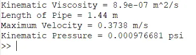
The generated blockMeshDict file was replaced with the original blockMeshDict file of the case.
blockMeshDict for 10 degree
The text file of blockMeshDict is very long & not possible to fit inside the screenshot. Because of that the text file has been presented here using insert code option.
/*--------------------------------*- C++ -*----------------------------------*\
  =========                 |
  \\      /  F ield         | OpenFOAM: The Open Source CFD Toolbox
   \\    /   O peration     | Website:  https://openfoam.org
    \\  /    A nd           | Version:  8
     \\/     M anipulation  |
\*---------------------------------------------------------------------------*/
FoamFile
{
    version     2.0;
    format      ascii;
    class       dictionary;
    object      blockMeshDict;
}
// * * * * * * * * * * * * * * * * * * * * * * * * * * * * * * * * * * * * * //

convertToMeters 1;

vertices
(
    (0.000000 0.000000 0.000000)
    (0.000436 0.004981 0.000000)
    (-0.000436 0.004981 0.000000)
    (0.000000 0.000000 1.440000)
    (0.000436 0.004981 1.440000)
    (-0.000436 0.004981 1.440000)
);

blocks
(
    hex (3 5 4 3 0 2 1 0) (50 1 200) simpleGrading (0.5 1 1)
);

edges
(
     arc 1 2 (-0.005000 0.005000 0.000000)
     arc 4 5 (-0.005000 0.005000 1.440000)
);

boundary
(
    inletWall
    {
        type patch;
        faces
        (
          (0 1 2 0)
        );
    }
    outletWall
    {
        type patch;
        faces
        (
          (3 5 4 3)
        );
    }
    front
    {
        type symmetry;
        faces
        (
          (3 4 1 0)
        );
    }
    back
    {
        type symmetry;
        faces
        (
          (0 2 5 3)
        );
    }
    wall
    {
        type wall;
        faces
        (
          (1 4 5 2)
        );
    }
    axis
    {
        type empty;
        faces
        (
          (0 3 3 0)
        );
    }
);

mergePatchPairs
(
);

// * * * * * * * * * * * * * * * * * * * * * * * * * * * * * * * * * * * * * //
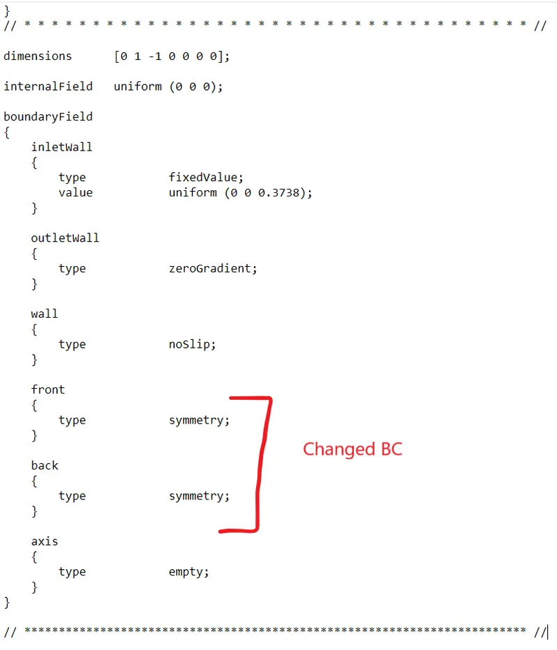
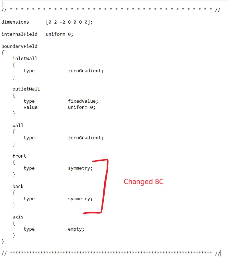
Parallel to the blockMeshDict file, the symmetry BC was also changed in the U & p dictionary file in following way.
U dictionary
p Dictionary
Results:
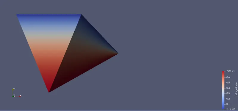
U magnitude
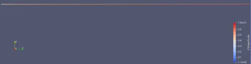
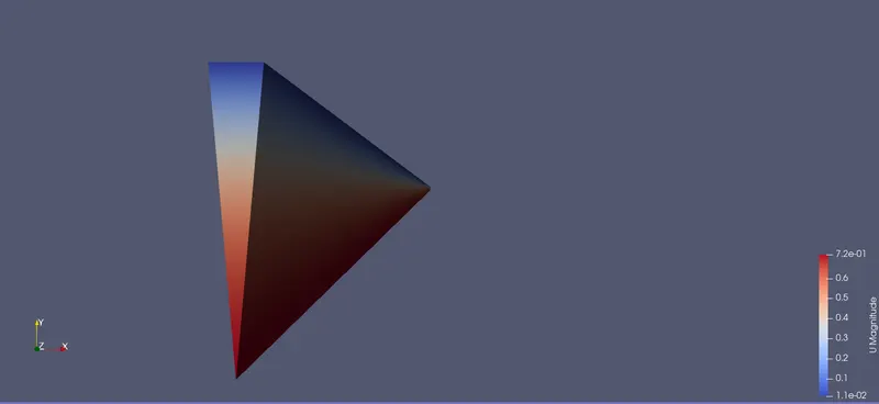
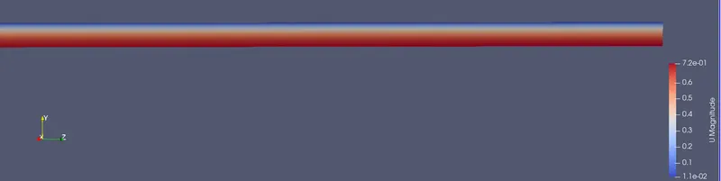
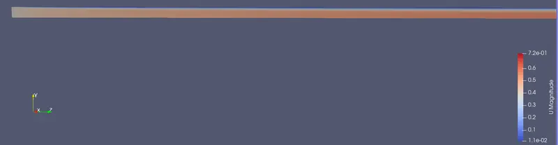
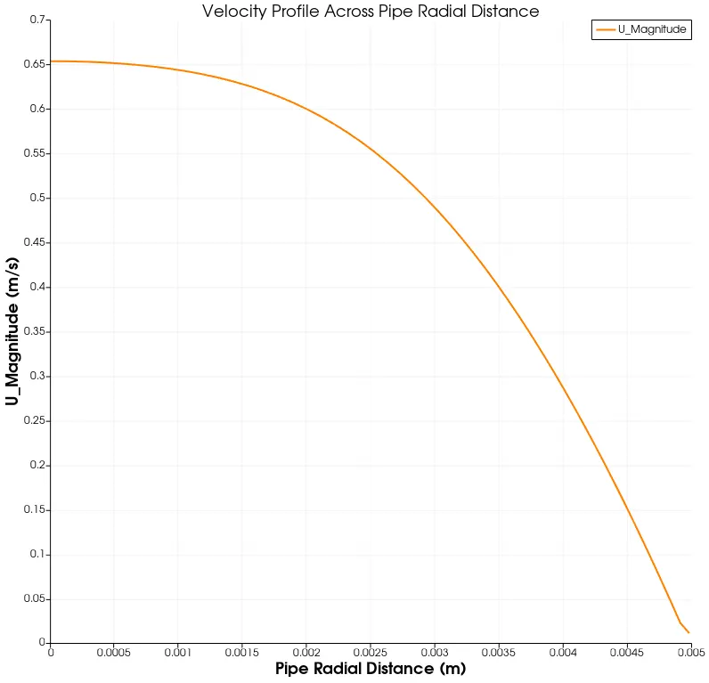
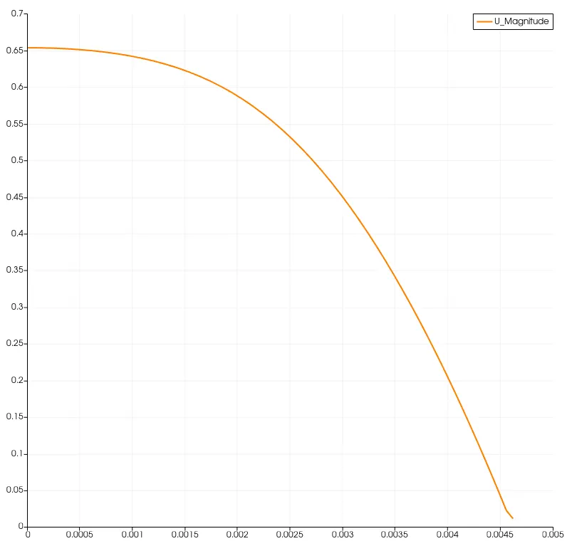
Line plot also plotted using "Plot over line" option to study the change in the velocity magnitude in the pipe radial direction. The line has been created in the middle of the pipe towards z-direction at a distance of 0.72m.
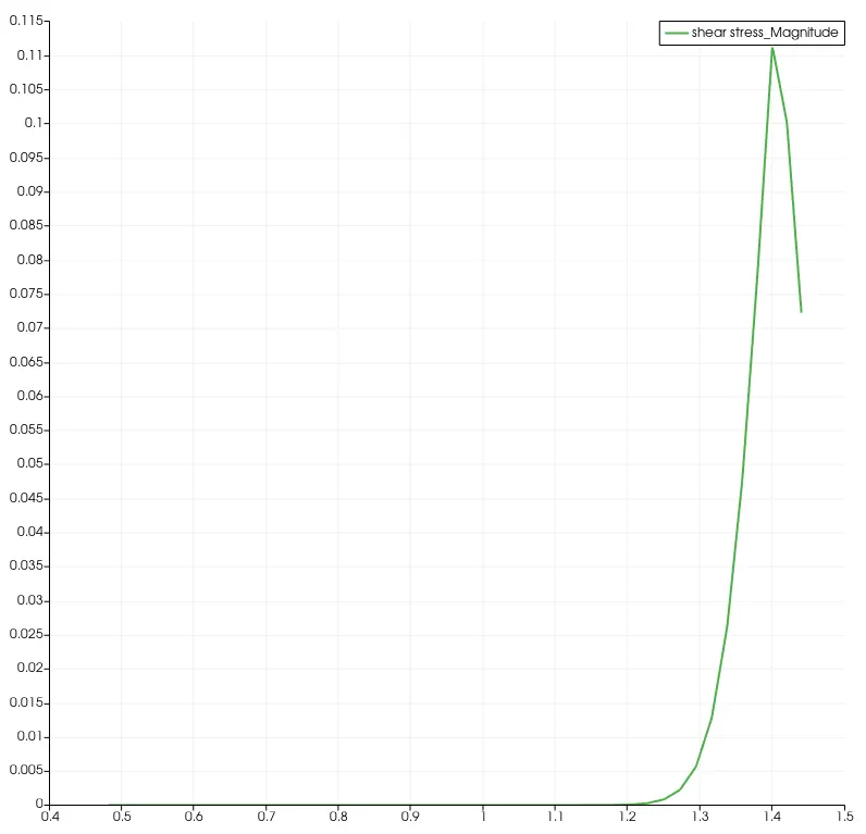
Shear Stress Plot
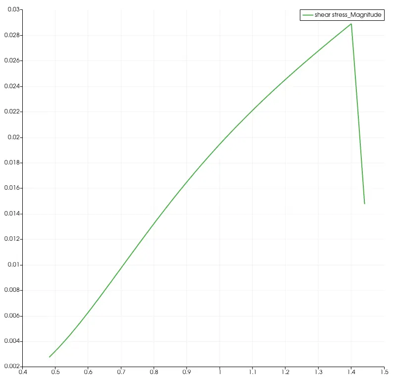
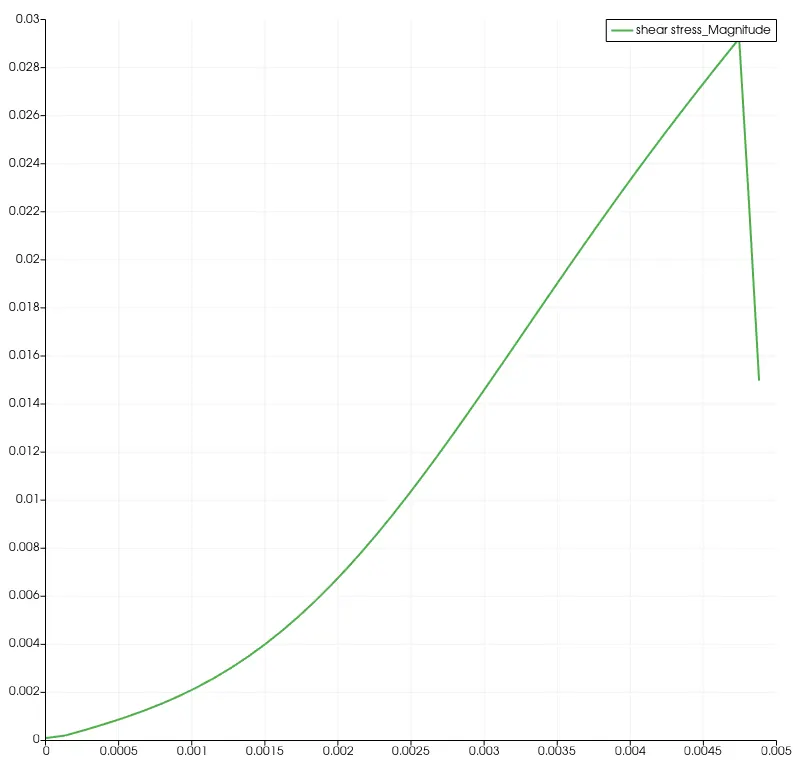
Shear Stress Plot has also beed created after creating magnitude of U varaible using "calculator" provided in the Paraview software. And "Gradient of the Unstructured Dataset" of previously created variable of U magnitude.
To create shear stress parameter in Paraview, the eqaution Dynamic Viscosity*U Magnitude needs to enter into the calculator. The created parameter of shear stress will be plotted using "Plot over Line" option. Only shear stress variable has been kept in the plot to visualize it properly.
In similar way, the results for 25 degree & 45 degree case has been executed. Results for both cases are as follows.
For 25 Degree:
blockMeshDict
/*--------------------------------*- C++ -*----------------------------------*\
  =========                 |
  \\      /  F ield         | OpenFOAM: The Open Source CFD Toolbox
   \\    /   O peration     | Website:  https://openfoam.org
    \\  /    A nd           | Version:  8
     \\/     M anipulation  |
\*---------------------------------------------------------------------------*/
FoamFile
{
    version     2.0;
    format      ascii;
    class       dictionary;
    object      blockMeshDict;
}
// * * * * * * * * * * * * * * * * * * * * * * * * * * * * * * * * * * * * * //

convertToMeters 1;

vertices
(
    (0.000000 0.000000 0.000000)
    (0.001082 0.004881 0.000000)
    (-0.001082 0.004881 0.000000)
    (0.000000 0.000000 1.440000)
    (0.001082 0.004881 1.440000)
    (-0.001082 0.004881 1.440000)
);

blocks
(
    hex (3 5 4 3 0 2 1 0) (50 1 200) simpleGrading (0.5 1 1)
);

edges
(
     arc 1 2 (-0.005000 0.005000 0.000000)
     arc 4 5 (-0.005000 0.005000 1.440000)
);

boundary
(
    inletWall
    {
        type patch;
        faces
        (
          (0 1 2 0)
        );
    }
    outletWall
    {
        type patch;
        faces
        (
          (3 5 4 3)
        );
    }
    front
    {
        type symmetry;
        faces
        (
          (3 4 1 0)
        );
    }
    back
    {
        type symmetry;
        faces
        (
          (0 2 5 3)
        );
    }
    wall
    {
        type wall;
        faces
        (
          (1 4 5 2)
        );
    }
    axis
    {
        type empty;
        faces
        (
          (0 3 3 0)
        );
    }
);

mergePatchPairs
(
);

// * * * * * * * * * * * * * * * * * * * * * * * * * * * * * * * * * * * * * //
Results for velocity
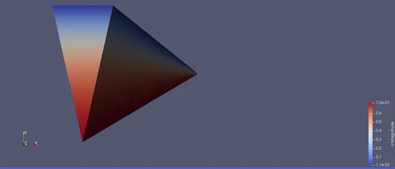
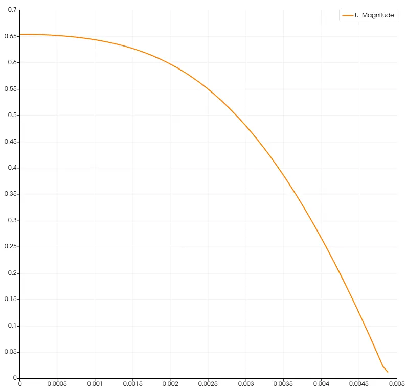
Remaining files of pressure (p) & velocity (U) are same as in the case of 10 degree case.
U_plot
Shear Stress Plot
For 45 Degree:
blockMeshDict
/*--------------------------------*- C++ -*----------------------------------*\
  =========                 |
  \\      /  F ield         | OpenFOAM: The Open Source CFD Toolbox
   \\    /   O peration     | Website:  https://openfoam.org
    \\  /    A nd           | Version:  8
     \\/     M anipulation  |
\*---------------------------------------------------------------------------*/
FoamFile
{
    version     2.0;
    format      ascii;
    class       dictionary;
    object      blockMeshDict;
}
// * * * * * * * * * * * * * * * * * * * * * * * * * * * * * * * * * * * * * //

convertToMeters 1;

vertices
(
    (0.000000 0.000000 0.000000)
    (0.001913 0.004619 0.000000)
    (-0.001913 0.004619 0.000000)
    (0.000000 0.000000 1.440000)
    (0.001913 0.004619 1.440000)
    (-0.001913 0.004619 1.440000)
);

blocks
(
    hex (3 5 4 3 0 2 1 0) (50 1 200) simpleGrading (0.5 1 1)
);

edges
(
     arc 1 2 (-0.005000 0.005000 0.000000)
     arc 4 5 (-0.005000 0.005000 1.440000)
);

boundary
(
    inletWall
    {
        type patch;
        faces
        (
          (0 1 2 0)
        );
    }
    outletWall
    {
        type patch;
        faces
        (
          (3 5 4 3)
        );
    }
    front
    {
        type symmetry;
        faces
        (
          (3 4 1 0)
        );
    }
    back
    {
        type symmetry;
        faces
        (
          (0 2 5 3)
        );
    }
    wall
    {
        type wall;
        faces
        (
          (1 4 5 2)
        );
    }
    axis
    {
        type empty;
        faces
        (
          (0 3 3 0)
        );
    }
);

mergePatchPairs
(
);

// * * * * * * * * * * * * * * * * * * * * * * * * * * * * * * * * * * * * * //
Results:
U magnitude
U Plot
Shear Stress Plot