Week 12 - Validation studies of Symmetry BC vs Wedge BC in OpenFOAM vs Analytical H.P equation
Challenges to be done in this exercise:
- Validate Hydro-dynamic length with the numerical result
- Validate the fully developed flow velocity profile with its analytical profile
- Validate maximum velocity and pressured drop for fully developed flow
- Post-process Shear stress and validate wall shear stress for fully developed flow
- Highligh the differences in both boundary conditions in terms of their usage and aplication
In the previous exercise we did only with the wedge boundary condition but in this challenge we will be doing the challenge with both symmetric boundary conditions and wedge boundary conditions at angle `10^o , 25^o and 45^o`respectively.
Wedge Boundary Conditions:
The wedge boundary condition is used in computational fluid dynamics to define an axisymmetric situation, for eg. a cylinder. The model and flow must be axisymmetric along a central line such that all physical variables of the flow have the same value and distribution at a given radius for all angles.
For the Symmetry BC, the angular changes that are considered don't affect or create an unsteady pattern for the path of attaining the convergence.
A Wedge boundary is different from the symmetry boundary condition in the sense that the wedge boundary condition applies the Navier-Stokes (NS) equations in cylindrical coordinates whereas the symmetric applies the NS equations in cartesian coordinates. One big advantage of wedge boundary is that it allows for the rotational flow around the axis and this is possible only because the fluxes and normal components are not assumed as zero.
This boundary condition is specified by two planes that must be selected on separate sides of the domain (referred to as front and back) on surfaces running along the axis.
Symmetry Boundary Conditions
The symmetry boundary condition defines a mirror face/surface. It should only be used if the physical object or geometry and the expected flow field pattern of the developed solution are mirrored along that surface. By using this boundary condition, the domain can essentially be halved, reducing the time to achieve a solution.
In detail, the symmetry condition applies the following constraints on the flow variables:
- The fluxes across the symmetry are zero.
- The normal components of all variables are set to zero.
It can be applied to both planar or non-planar faces/surfaces on the domain boundaries.
This boundary condition is used to apply mirror-symmetry conditions on a structure.
It can be applied to faces of a structure and no other user input is needed. If a symmetry plane condition is applied to a face, the displacement of this face is locked in a normal direction but free to slide in tangential directions.
For Wedge boundary conditions at an angle of 10*
Generate a code in the MATLAB similarly to the previous challenge where we have to change the angle to 10 degrees as per the requirement as shown below:
% SIMULATION OF FLOW THROUGH A PIPE
% Code to automate generation of blockMeshDict file
clear all
close all
clc


% INPUTS
% Assumptions
% Diameter of Pipe (m)
D = 0.02;

% Radius of Pipe (m)
R = D/2;

% Reynold's Number
Re = 2100;

% Wedge Angle (degrees)
theta = 10;

% Total Length of the Pipe (m)
L = 2.8;


% Assuming working fluid is water at 25° C
% Density of water (kg/m³)
rho = 997;

% Dynamic Viscosity of Water (Pa.s)
mu = 8.90 * 10^-4;

% Kinematic Viscosity of Water (m^2/s)
nu = mu/rho;


% Hydrodynamic Entrance Length (m)
L_h = 138* D;


% HAGEN - POISEUILLE'S FLOW EQUATIONS
% Average Velocity (m/s)
V_avg = (mu * Re)/(rho * D);

% Maximum Velocity (m/s)
V_max = 2 * V_avg;

% Pressure Drop (Pa)
delta_p = (32*mu*V_avg*L)/(D^2);

% Kinematic Pressure Drop (Pa)
kinematic_delta_p = delta_p/rho;


% DEFINING THE GEOMETRY
% Vertices
V0 = [0 0 0];
V1 = [0 R*cosd(theta/2) -R*sind(theta/2)];
V2 = [0 R*cosd(theta/2) R*sind(theta/2)];

V3 = [L 0 0];
V4 = [L R*cosd(theta/2) -R*sind(theta/2)];
V5 = [L R*cosd(theta/2) R*sind(theta/2)];


% BLOCKMESHDICT FILE
% Creating the file
% Header
h1 = '/*--------------------------------*- C++ -*----------------------------------*\';
h2 = '  =========                 |';
h3 = '  \\      /  F ield         | OpenFOAM: The Open Source CFD Toolbox';
h4 = '   \\    /   O peration     | Website:  https://openfoam.org';
h5 = '    \\  /    A nd           | Version:  9';
h6 = '     \\/     M anipulation  |';
h7 = '\*---------------------------------------------------------------------------*/';
h8 = 'FoamFile';
h9 = '{';
h10 = '    format      ascii;';
h11 = '    class       dictionary;';
h12 = '    object      blockMeshDict;';
h13 = '}';
h14 = '// * * * * * * * * * * * * * * * * * * * * * * * * * * * * * * * * * * * * * //';


% Creating BlockMesh File
f1 = fopen('blockMeshDict.txt','w');

% Header
fprintf(f1,'%s\n',h1);
fprintf(f1,'%s\n',h2);
fprintf(f1,'%s\n',h3);
fprintf(f1,'%s\n',h4);
fprintf(f1,'%s\n',h5);
fprintf(f1,'%s\n',h6);
fprintf(f1,'%s\n',h7);
fprintf(f1,'%s\n',h8);
fprintf(f1,'%s\n',h9);
fprintf(f1,'%s\n',h10);
fprintf(f1,'%s\n',h11);
fprintf(f1,'%s\n',h12);
fprintf(f1,'%s\n',h13);
fprintf(f1,'%s\n\n',h14);

% Conversion Factor
fprintf(f1,'%s\n\n','convertToMeters 1;');

% Vertices
fprintf(f1,'%s\n','vertices');
fprintf(f1,'%s\n','(');
fprintf(f1,'\t(%d %d %d)\n',V0);
fprintf(f1,'\t(%d %f %f)\n',V1);
fprintf(f1,'\t(%d %f %f)\n',V2);
fprintf(f1,'\t(%.2f %d %d)\n',V3);
fprintf(f1,'\t(%.2f %f %f)\n',V4);
fprintf(f1,'\t(%.2f %f %f)\n',V5);
fprintf(f1,'%s\n\n',');');

% Blocks
fprintf(f1,'%s\n','blocks');
fprintf(f1,'%s\n','(');
fprintf(f1,'\t hex (0 3 4 1 0 3 5 2) (50 10 1) simpleGrading (1 1 1)\n');
fprintf(f1,'%s\n\n',');');

% Edges
fprintf(f1,'%s\n','edges');
fprintf(f1,'%s\n','(');
fprintf(f1,'\tarc 2 1 (%d %.3f %d)\n',0,R,0);
fprintf(f1,'\tarc 4 5 (%.3f %.3f %d)\n',L,R,0);
fprintf(f1,'%s\n\n',');');

% Boundary
fprintf(f1,'%s\n','boundary');
fprintf(f1,'%s\n','(');

% Axis
fprintf(f1,'\taxis\n');
fprintf(f1,'\t{\n');
fprintf(f1,'\t\ttype empty;\n');
fprintf(f1,'\t\tfaces\n');
fprintf(f1,'\t\t(\n');
fprintf(f1,'\t\t\t(0 3 3 0)\n');
fprintf(f1,'\t\t);\n');
fprintf(f1,'\t}\n\n');

% Inlet
fprintf(f1,'\tinlet\n');
fprintf(f1,'\t{\n');
fprintf(f1,'\t\ttype patch;\n');
fprintf(f1,'\t\tfaces\n');
fprintf(f1,'\t\t(\n');
fprintf(f1,'\t\t\t(0 2 1 0)\n');
fprintf(f1,'\t\t);\n');
fprintf(f1,'\t}\n\n');

% Outlet
fprintf(f1,'\toutlet\n');
fprintf(f1,'\t{\n');
fprintf(f1,'\t\ttype patch;\n');
fprintf(f1,'\t\tfaces\n');
fprintf(f1,'\t\t(\n');
fprintf(f1,'\t\t\t(3 4 5 3)\n');
fprintf(f1,'\t\t);\n');
fprintf(f1,'\t}\n\n');

% Front Face
fprintf(f1,'\tfront\n');
fprintf(f1,'\t{\n');
fprintf(f1,'\t\ttype wedge;\n');
fprintf(f1,'\t\tfaces\n');
fprintf(f1,'\t\t(\n');
fprintf(f1,'\t\t\t(0 3 5 2)\n');
fprintf(f1,'\t\t);\n');
fprintf(f1,'\t}\n\n');

% Back Face
fprintf(f1,'\tback\n');
fprintf(f1,'\t{\n');
fprintf(f1,'\t\ttype wedge;\n');
fprintf(f1,'\t\tfaces\n');
fprintf(f1,'\t\t(\n');
fprintf(f1,'\t\t\t(0 1 4 3)\n');
fprintf(f1,'\t\t);\n');
fprintf(f1,'\t}\n\n');

% Top Wall
fprintf(f1,'\tpipeWall\n');
fprintf(f1,'\t{\n');
fprintf(f1,'\t\ttype wall;\n');
fprintf(f1,'\t\tfaces\n');
fprintf(f1,'\t\t(\n');
fprintf(f1,'\t\t\t(1 2 5 4)\n');
fprintf(f1,'\t\t);\n');
fprintf(f1,'\t}\n');

fprintf(f1,'%s\n\n',');');
fprintf(f1,'%s\n','mergePatchPairs');
fprintf(f1,'%s\n','(');
fprintf(f1,'%s\n\n',');');
fprintf(f1,'%s\n','// ************************************************************************* //');
After writing the code in the matlab and running it we will be getting the file named blockMeshDict which we have to paste it in the directory of the open foam where we are running it to get the geometry as shown below:
/*--------------------------------*- C++ -*----------------------------------*\
  =========                 |
  \\      /  F ield         | OpenFOAM: The Open Source CFD Toolbox
   \\    /   O peration     | Website:  https://openfoam.org
    \\  /    A nd           | Version:  9
     \\/     M anipulation  |
\*---------------------------------------------------------------------------*/
FoamFile
{
    format      ascii;
    class       dictionary;
    object      blockMeshDict;
}
// * * * * * * * * * * * * * * * * * * * * * * * * * * * * * * * * * * * * * //

convertToMeters 1;

vertices
(
	(0 0 0)
	(0 0.009962 -0.000872)
	(0 0.009962 0.000872)
	(2.80 0 0)
	(2.80 0.009962 -0.000872)
	(2.80 0.009962 0.000872)
);

blocks
(
	hex (0 3 4 1 0 3 5 2) (50 10 1) simpleGrading (1 1 1)
);

edges
(
	arc 2 1 (0 0.010 0)
	arc 4 5 (2.800 0.010 0)
);

boundary
(
	axis
	{
		type empty;
		faces
		(
			(0 3 3 0)
		);
	}

	inlet
	{
		type patch;
		faces
		(
			(0 2 1 0)
		);
	}

	outlet
	{
		type patch;
		faces
		(
			(3 4 5 3)
		);
	}

	front
	{
		type wedge;
		faces
		(
			(0 3 5 2)
		);
	}

	back
	{
		type wedge;
		faces
		(
			(0 1 4 3)
		);
	}

	pipeWall
	{
		type wall;
		faces
		(
			(1 2 5 4)
		);
	}
);

mergePatchPairs
(
);

// ************************************************************************* //
After changing it we have to change the properties in controlDict file pressure file and velocity file.
ControlDict file:
/*--------------------------------*- C++ -*----------------------------------*\
  =========                 |
  \\      /  F ield         | OpenFOAM: The Open Source CFD Toolbox
   \\    /   O peration     | Website:  https://openfoam.org
    \\  /    A nd           | Version:  10
     \\/     M anipulation  |
\*---------------------------------------------------------------------------*/
FoamFile
{
    format      ascii;
    class       dictionary;
    location    "system";
    object      controlDict;
}
// * * * * * * * * * * * * * * * * * * * * * * * * * * * * * * * * * * * * * //

application     icoFoam;

startFrom       startTime;

startTime       0;

stopAt          endTime;

endTime         30;

deltaT          0.05;

writeControl    timeStep;

writeInterval   200;

purgeWrite      0;

writeFormat     ascii;

writePrecision  6;

writeCompression off;

timeFormat      general;

timePrecision   6;

runTimeModifiable true;


// ************************************************************************* //
- End Time :- To decide suitable end time we will first decide minimum time required to run simulation by formula Velocity = Dist / Time
Time required = Total length / Avg velocity
= 2.8/0.0937 =29.88 Sec
So, we will put value of end time 30 Sec
- Delta T :- We will check for 0.01 if found error we will change value according to required number of Iterations to solve.
- In this case for Delta T = 0.01 it took so much time to run so we will change Delta T = 0.05
- Write Interval :- This defines time after which new interval decides and new folder created for that each interval. So if interval value is less, solver take so many intervals so we will increase value accordingly.
- In this case for Write Interval = 20, it took so many interval to run so we will change Write Interval = 200
Pressure File (p):
Change the file as per requirement as shown below:
/*--------------------------------*- C++ -*----------------------------------*\
  =========                 |
  \\      /  F ield         | OpenFOAM: The Open Source CFD Toolbox
   \\    /   O peration     | Website:  https://openfoam.org
    \\  /    A nd           | Version:  10
     \\/     M anipulation  |
\*---------------------------------------------------------------------------*/
FoamFile
{
    format      ascii;
    class       volScalarField;
    object      p;
}
// * * * * * * * * * * * * * * * * * * * * * * * * * * * * * * * * * * * * * //

dimensions      [0 1 -1 0 0 0 0];

internalField   uniform 0;

boundaryField
{
    axis
    {
        type            empty;
    }

    inlet
    {
        type            zeroGradient;
    }

    outlet
    {
        type            fixedValue;
        value           uniform 0;
    }

    front
    {
        type            wedge;
    }

    back
    {
        type            wedge;
    }

    pipeWall
    {
        type            zeroGradient;
    }
}

// ************************************************************************* //
Velocity file (U):
Change the file as per the requirement as shown below:
/*--------------------------------*- C++ -*----------------------------------*\
  =========                 |
  \\      /  F ield         | OpenFOAM: The Open Source CFD Toolbox
   \\    /   O peration     | Website:  https://openfoam.org
    \\  /    A nd           | Version:  10
     \\/     M anipulation  |
\*---------------------------------------------------------------------------*/
FoamFile
{
    format      ascii;
    class       volVectorField;
    object      U;
}
// * * * * * * * * * * * * * * * * * * * * * * * * * * * * * * * * * * * * * //

dimensions      [0 1 -1 0 0 0 0];

internalField   uniform (0 0 0);

boundaryField
{
    axis
    {
        type            empty;
    }

    inlet
    {
        type            fixedValue;
        value           uniform (1 0 0);
    }

    outlet
    {
        type            zeroGradient;
    }

    front
    {
        type            wedge;
    }

    back
    {
        type            wedge;
    }

    pipeWall
    {
        type            noSlip;
    }
}

// ************************************************************************* //
Physical Properties:
/*--------------------------------*- C++ -*----------------------------------*\
  =========                 |
  \\      /  F ield         | OpenFOAM: The Open Source CFD Toolbox
   \\    /   O peration     | Website:  https://openfoam.org
    \\  /    A nd           | Version:  10
     \\/     M anipulation  |
\*---------------------------------------------------------------------------*/
FoamFile
{
    format      ascii;
    class       dictionary;
    location    "constant";
    object      physicalProperties;
}
// * * * * * * * * * * * * * * * * * * * * * * * * * * * * * * * * * * * * * //

nu              [0 1 -1 0 0 0 0] 8.92e-7;


// ************************************************************************* //
After editing all the files in the directory we have to check the blockMesh and then check the mesh with the checkMesh comand then run the icoFoam after checking all of it then we can enter the paraView to check the mesh and to simulate it.
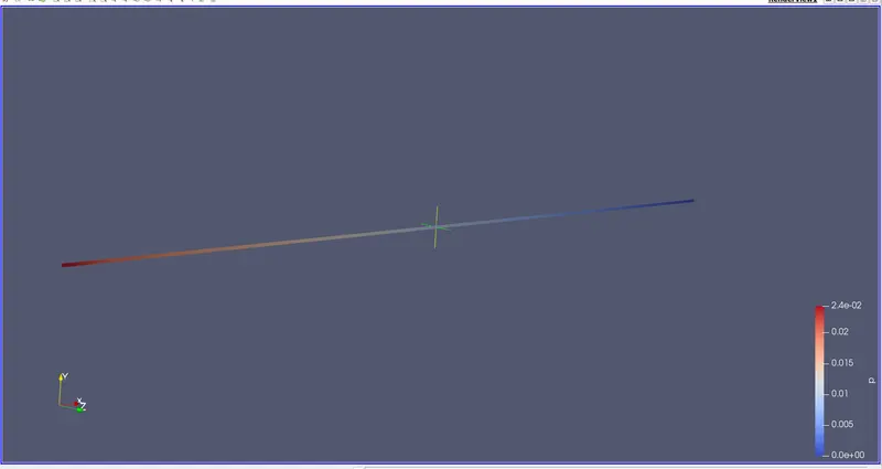
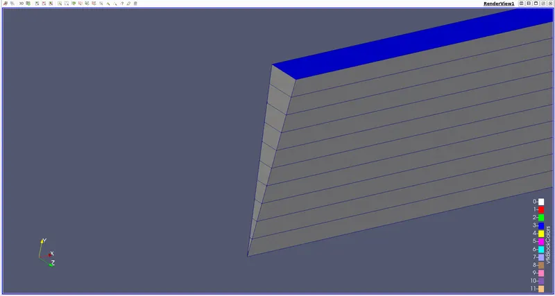
The below is the geometry of the file which we edited it through matlab code. We can see the meshing is done and the angle of the wedge is 10 degrees.
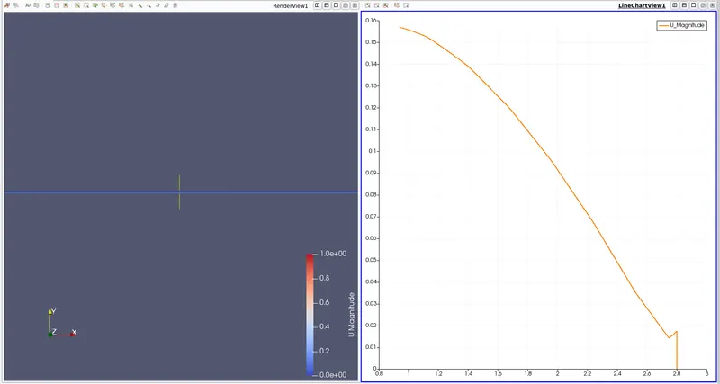
NOw the velocity contour and velocity profile of the wedge:
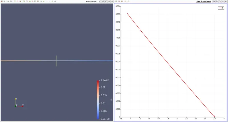
Now the pressure contour and pressure profile of the geometry.
Now the fully developed flow velocity profile is obtained at the length of 1.9m from the inlet where can see the velocity profile of it.
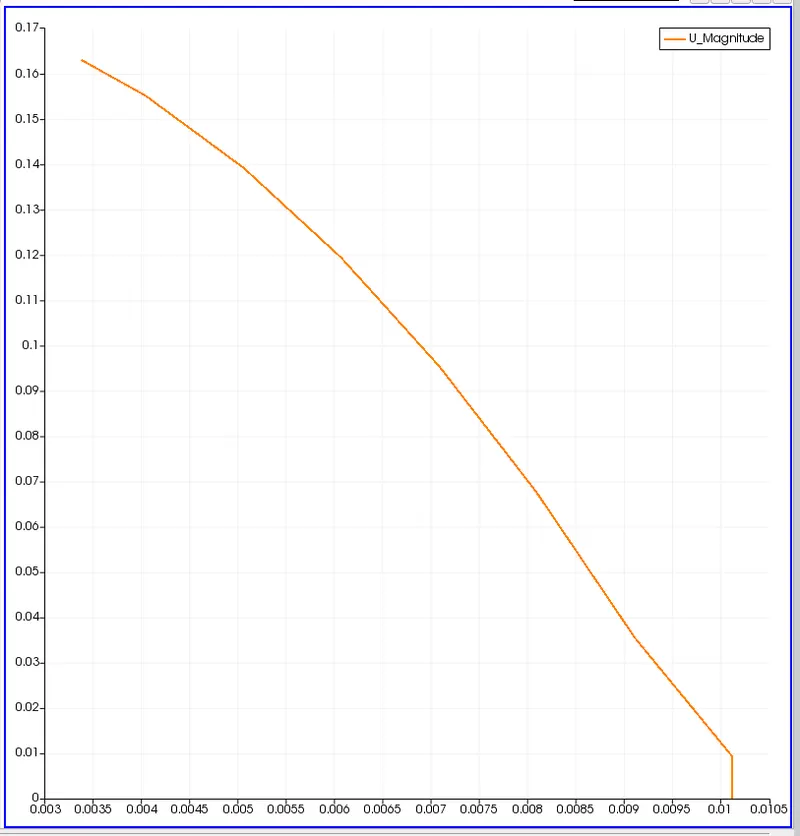
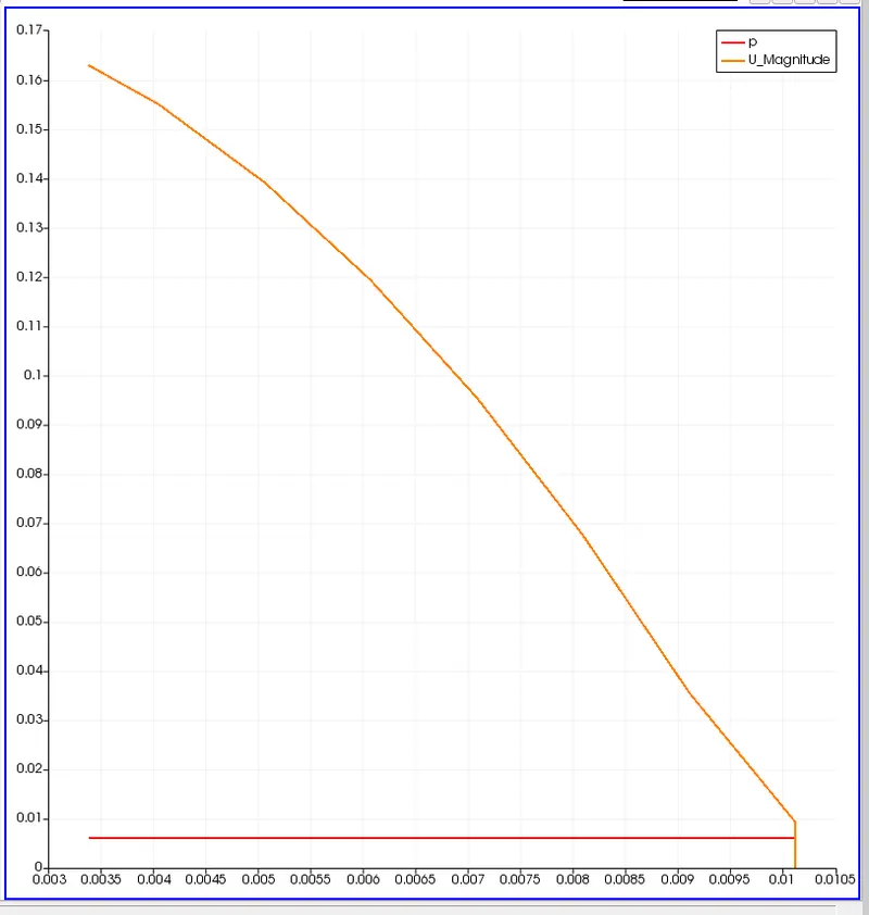
Now we are validating the maximum velocity and pressured drop for fully developed flow:
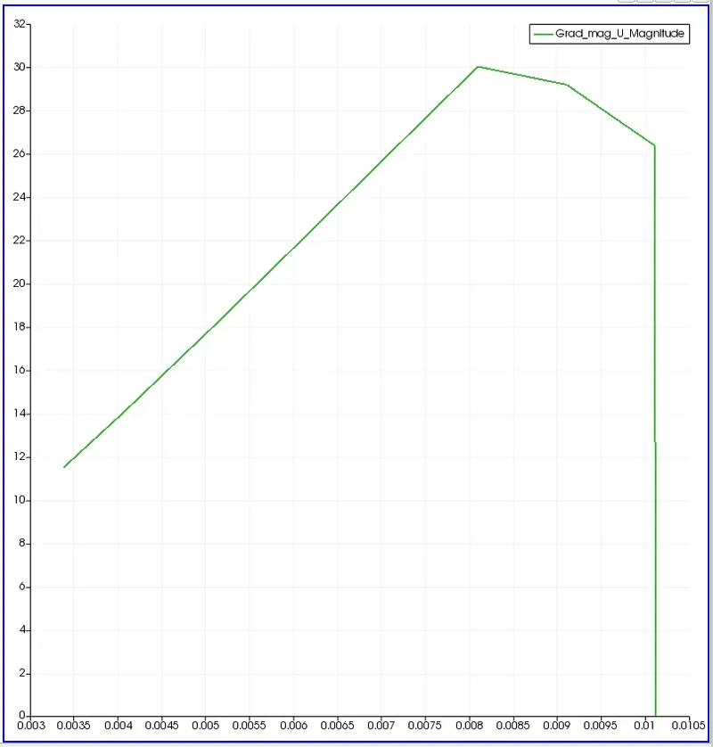
Post-process Shear stress and validating wall shear stress for fully developed flow of the geometry.
Wall shear stress for fully developed flow of the geometry
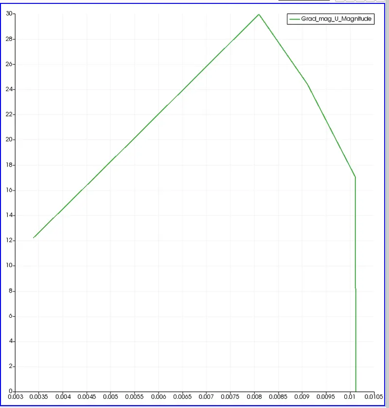
Post shear stress for the fully developed flow of the geometry.
For wedge boundary Conditions at an angloe of 25 degrees:
Generate a code in the MATLAB similarly to the previous angle of 10 degress where we have to change the angle to 25 degrees as per the requirement as shown below:
% SIMULATION OF FLOW THROUGH A PIPE
% Code to automate generation of blockMeshDict file
clear all
close all
clc


% INPUTS
% Assumptions
% Diameter of Pipe (m)
D = 0.02;

% Radius of Pipe (m)
R = D/2;

% Reynold's Number
Re = 2100;

% Wedge Angle (degrees)
theta = 25;

% Total Length of the Pipe (m)
L = 2.8;


% Assuming working fluid is water at 25° C
% Density of water (kg/m³)
rho = 997;

% Dynamic Viscosity of Water (Pa.s)
mu = 8.90 * 10^-4;

% Kinematic Viscosity of Water (m^2/s)
nu = mu/rho;


% Hydrodynamic Entrance Length (m)
L_h = 138* D;


% HAGEN - POISEUILLE'S FLOW EQUATIONS
% Average Velocity (m/s)
V_avg = (mu * Re)/(rho * D);

% Maximum Velocity (m/s)
V_max = 2 * V_avg;

% Pressure Drop (Pa)
delta_p = (32*mu*V_avg*L)/(D^2);

% Kinematic Pressure Drop (Pa)
kinematic_delta_p = delta_p/rho;


% DEFINING THE GEOMETRY
% Vertices
V0 = [0 0 0];
V1 = [0 R*cosd(theta/2) -R*sind(theta/2)];
V2 = [0 R*cosd(theta/2) R*sind(theta/2)];

V3 = [L 0 0];
V4 = [L R*cosd(theta/2) -R*sind(theta/2)];
V5 = [L R*cosd(theta/2) R*sind(theta/2)];


% BLOCKMESHDICT FILE
% Creating the file
% Header
h1 = '/*--------------------------------*- C++ -*----------------------------------*\';
h2 = '  =========                 |';
h3 = '  \\      /  F ield         | OpenFOAM: The Open Source CFD Toolbox';
h4 = '   \\    /   O peration     | Website:  https://openfoam.org';
h5 = '    \\  /    A nd           | Version:  9';
h6 = '     \\/     M anipulation  |';
h7 = '\*---------------------------------------------------------------------------*/';
h8 = 'FoamFile';
h9 = '{';
h10 = '    format      ascii;';
h11 = '    class       dictionary;';
h12 = '    object      blockMeshDict;';
h13 = '}';
h14 = '// * * * * * * * * * * * * * * * * * * * * * * * * * * * * * * * * * * * * * //';


% Creating BlockMesh File
f1 = fopen('blockMeshDict.txt','w');

% Header
fprintf(f1,'%s\n',h1);
fprintf(f1,'%s\n',h2);
fprintf(f1,'%s\n',h3);
fprintf(f1,'%s\n',h4);
fprintf(f1,'%s\n',h5);
fprintf(f1,'%s\n',h6);
fprintf(f1,'%s\n',h7);
fprintf(f1,'%s\n',h8);
fprintf(f1,'%s\n',h9);
fprintf(f1,'%s\n',h10);
fprintf(f1,'%s\n',h11);
fprintf(f1,'%s\n',h12);
fprintf(f1,'%s\n',h13);
fprintf(f1,'%s\n\n',h14);

% Conversion Factor
fprintf(f1,'%s\n\n','convertToMeters 1;');

% Vertices
fprintf(f1,'%s\n','vertices');
fprintf(f1,'%s\n','(');
fprintf(f1,'\t(%d %d %d)\n',V0);
fprintf(f1,'\t(%d %f %f)\n',V1);
fprintf(f1,'\t(%d %f %f)\n',V2);
fprintf(f1,'\t(%.2f %d %d)\n',V3);
fprintf(f1,'\t(%.2f %f %f)\n',V4);
fprintf(f1,'\t(%.2f %f %f)\n',V5);
fprintf(f1,'%s\n\n',');');

% Blocks
fprintf(f1,'%s\n','blocks');
fprintf(f1,'%s\n','(');
fprintf(f1,'\t hex (0 3 4 1 0 3 5 2) (50 10 1) simpleGrading (1 1 1)\n');
fprintf(f1,'%s\n\n',');');

% Edges
fprintf(f1,'%s\n','edges');
fprintf(f1,'%s\n','(');
fprintf(f1,'\tarc 2 1 (%d %.3f %d)\n',0,R,0);
fprintf(f1,'\tarc 4 5 (%.3f %.3f %d)\n',L,R,0);
fprintf(f1,'%s\n\n',');');

% Boundary
fprintf(f1,'%s\n','boundary');
fprintf(f1,'%s\n','(');

% Axis
fprintf(f1,'\taxis\n');
fprintf(f1,'\t{\n');
fprintf(f1,'\t\ttype empty;\n');
fprintf(f1,'\t\tfaces\n');
fprintf(f1,'\t\t(\n');
fprintf(f1,'\t\t\t(0 3 3 0)\n');
fprintf(f1,'\t\t);\n');
fprintf(f1,'\t}\n\n');

% Inlet
fprintf(f1,'\tinlet\n');
fprintf(f1,'\t{\n');
fprintf(f1,'\t\ttype patch;\n');
fprintf(f1,'\t\tfaces\n');
fprintf(f1,'\t\t(\n');
fprintf(f1,'\t\t\t(0 2 1 0)\n');
fprintf(f1,'\t\t);\n');
fprintf(f1,'\t}\n\n');

% Outlet
fprintf(f1,'\toutlet\n');
fprintf(f1,'\t{\n');
fprintf(f1,'\t\ttype patch;\n');
fprintf(f1,'\t\tfaces\n');
fprintf(f1,'\t\t(\n');
fprintf(f1,'\t\t\t(3 4 5 3)\n');
fprintf(f1,'\t\t);\n');
fprintf(f1,'\t}\n\n');

% Front Face
fprintf(f1,'\tfront\n');
fprintf(f1,'\t{\n');
fprintf(f1,'\t\ttype wedge;\n');
fprintf(f1,'\t\tfaces\n');
fprintf(f1,'\t\t(\n');
fprintf(f1,'\t\t\t(0 3 5 2)\n');
fprintf(f1,'\t\t);\n');
fprintf(f1,'\t}\n\n');

% Back Face
fprintf(f1,'\tback\n');
fprintf(f1,'\t{\n');
fprintf(f1,'\t\ttype wedge;\n');
fprintf(f1,'\t\tfaces\n');
fprintf(f1,'\t\t(\n');
fprintf(f1,'\t\t\t(0 1 4 3)\n');
fprintf(f1,'\t\t);\n');
fprintf(f1,'\t}\n\n');

% Top Wall
fprintf(f1,'\tpipeWall\n');
fprintf(f1,'\t{\n');
fprintf(f1,'\t\ttype wall;\n');
fprintf(f1,'\t\tfaces\n');
fprintf(f1,'\t\t(\n');
fprintf(f1,'\t\t\t(1 2 5 4)\n');
fprintf(f1,'\t\t);\n');
fprintf(f1,'\t}\n');

fprintf(f1,'%s\n\n',');');
fprintf(f1,'%s\n','mergePatchPairs');
fprintf(f1,'%s\n','(');
fprintf(f1,'%s\n\n',');');
fprintf(f1,'%s\n','// ************************************************************************* //');
Now the blockMeshDict file is generated as shown below:
/*--------------------------------*- C++ -*----------------------------------*\
  =========                 |
  \\      /  F ield         | OpenFOAM: The Open Source CFD Toolbox
   \\    /   O peration     | Website:  https://openfoam.org
    \\  /    A nd           | Version:  9
     \\/     M anipulation  |
\*---------------------------------------------------------------------------*/
FoamFile
{
    format      ascii;
    class       dictionary;
    object      blockMeshDict;
}
// * * * * * * * * * * * * * * * * * * * * * * * * * * * * * * * * * * * * * //

convertToMeters 1;

vertices
(
	(0 0 0)
	(0 0.009763 -0.002164)
	(0 0.009763 0.002164)
	(2.80 0 0)
	(2.80 0.009763 -0.002164)
	(2.80 0.009763 0.002164)
);

blocks
(
	 hex (0 3 4 1 0 3 5 2) (50 10 1) simpleGrading (1 1 1)
);

edges
(
	arc 2 1 (0 0.010 0)
	arc 4 5 (2.800 0.010 0)
);

boundary
(
	axis
	{
		type empty;
		faces
		(
			(0 3 3 0)
		);
	}

	inlet
	{
		type patch;
		faces
		(
			(0 2 1 0)
		);
	}

	outlet
	{
		type patch;
		faces
		(
			(3 4 5 3)
		);
	}

	front
	{
		type wedge;
		faces
		(
			(0 3 5 2)
		);
	}

	back
	{
		type wedge;
		faces
		(
			(0 1 4 3)
		);
	}

	pipeWall
	{
		type wall;
		faces
		(
			(1 2 5 4)
		);
	}
);

mergePatchPairs
(
);

// ************************************************************************* //
Let the remaining files be same as the previous one no need to change any of the pressure, velocity, controlDict and physical properties.
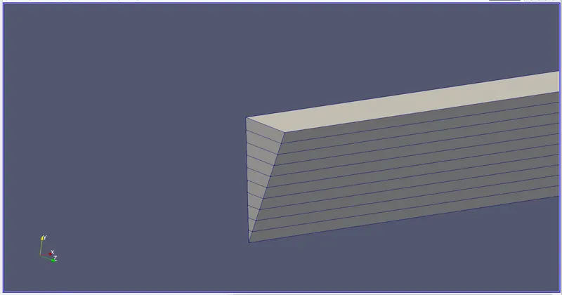
Now the geometry of the figure with the meshing of angle 25 degrees is as shown below:
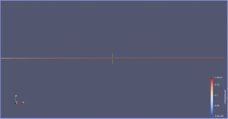
Below is the wedge boundary conditions with an angle of 25 with meshing
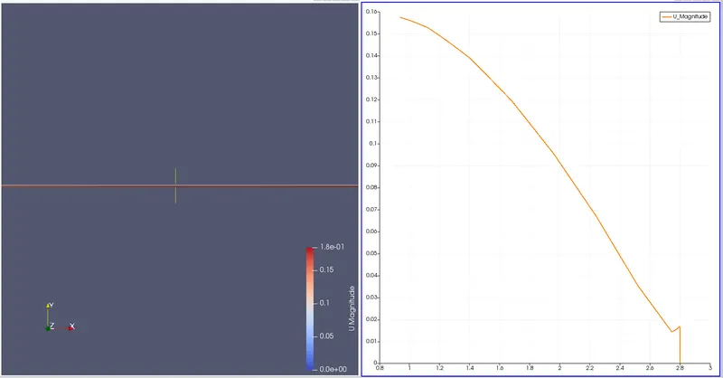
Velocity contour and velocity profile:
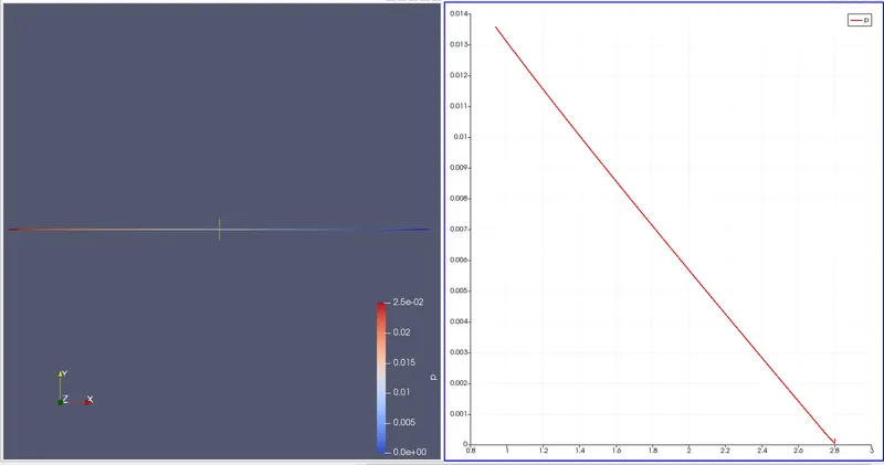
Pressure contour and pressure profile:
Max velocity and pressure drop for fully developed flow:
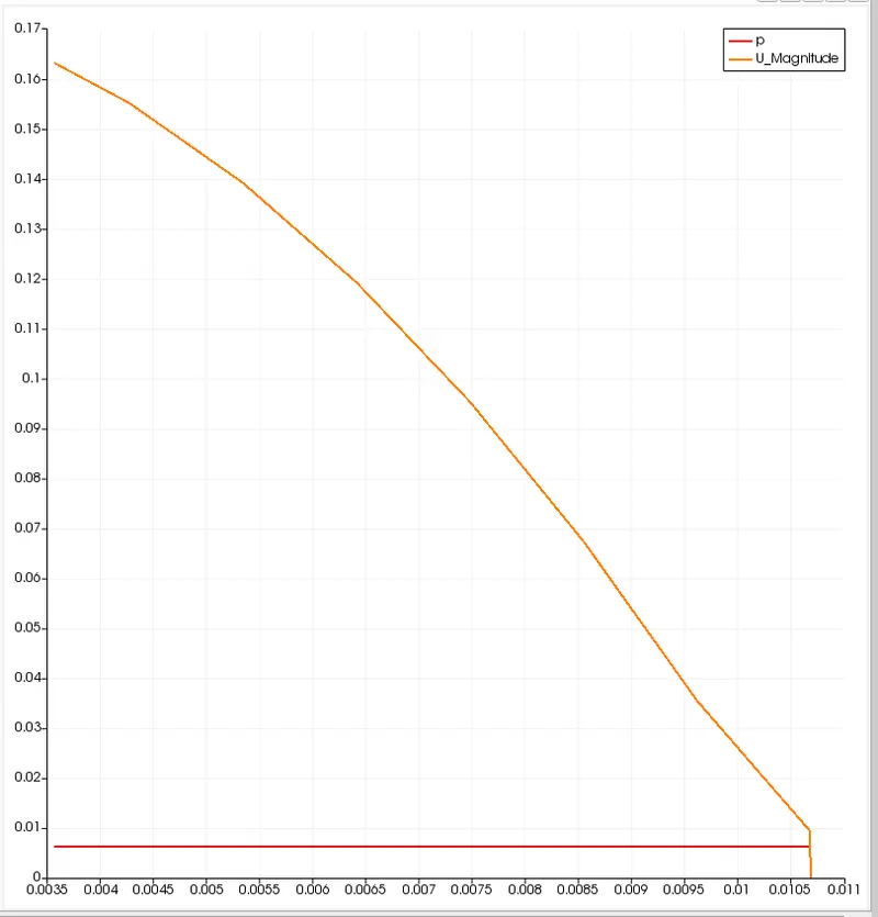
Fully developed flow velocity profile :
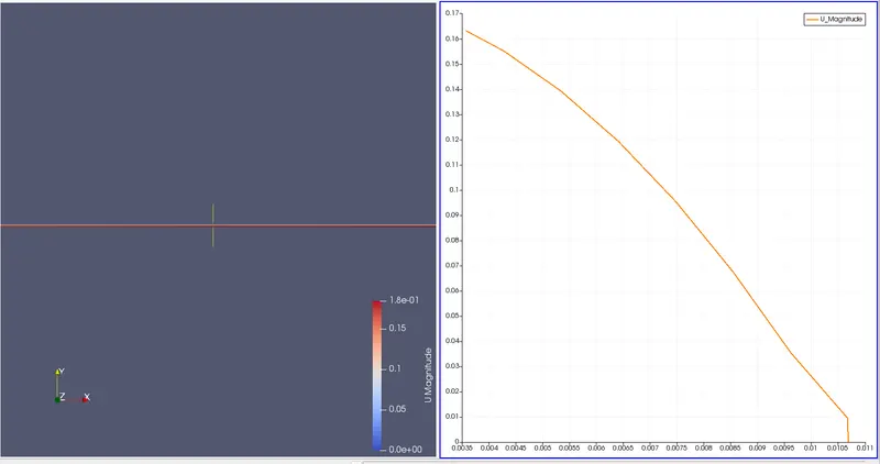
Post shear stress for the fully developed flow of the geometry.
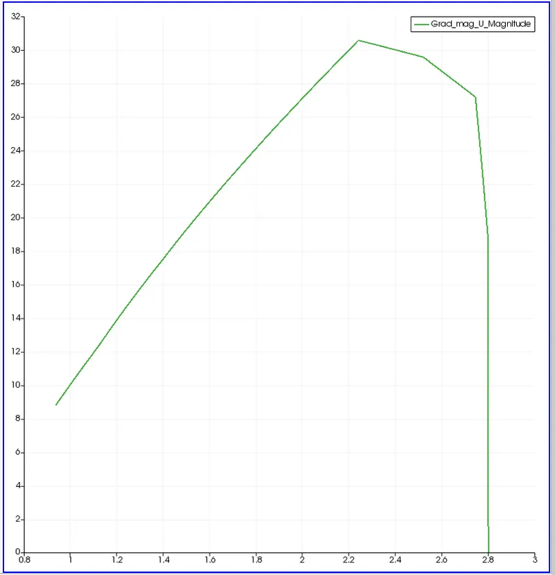
Wall shear stress for fully developed flow of the geometry.
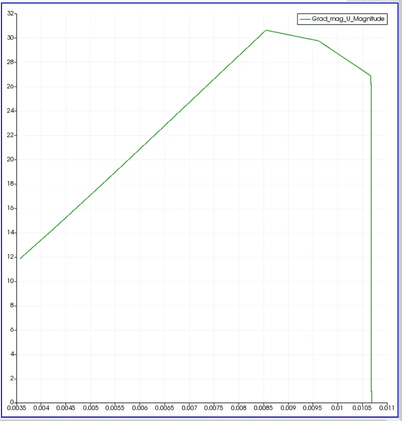
For wedge boundary conditions at an angle 45:
Generate a code in the MATLAB similarly to the previous angle of 10 degress where we have to change the angle to 45 degrees as per the requirement as shown below:
% SIMULATION OF FLOW THROUGH A PIPE
% Code to automate generation of blockMeshDict file
clear all
close all
clc


% INPUTS
% Assumptions
% Diameter of Pipe (m)
D = 0.02;

% Radius of Pipe (m)
R = D/2;

% Reynold's Number
Re = 2100;

% Wedge Angle (degrees)
theta = 45;

% Total Length of the Pipe (m)
L = 2.8;


% Assuming working fluid is water at 25° C
% Density of water (kg/m³)
rho = 997;

% Dynamic Viscosity of Water (Pa.s)
mu = 8.90 * 10^-4;

% Kinematic Viscosity of Water (m^2/s)
nu = mu/rho;


% Hydrodynamic Entrance Length (m)
L_h = 138* D;


% HAGEN - POISEUILLE'S FLOW EQUATIONS
% Average Velocity (m/s)
V_avg = (mu * Re)/(rho * D);

% Maximum Velocity (m/s)
V_max = 2 * V_avg;

% Pressure Drop (Pa)
delta_p = (32*mu*V_avg*L)/(D^2);

% Kinematic Pressure Drop (Pa)
kinematic_delta_p = delta_p/rho;


% DEFINING THE GEOMETRY
% Vertices
V0 = [0 0 0];
V1 = [0 R*cosd(theta/2) -R*sind(theta/2)];
V2 = [0 R*cosd(theta/2) R*sind(theta/2)];

V3 = [L 0 0];
V4 = [L R*cosd(theta/2) -R*sind(theta/2)];
V5 = [L R*cosd(theta/2) R*sind(theta/2)];


% BLOCKMESHDICT FILE
% Creating the file
% Header
h1 = '/*--------------------------------*- C++ -*----------------------------------*\';
h2 = '  =========                 |';
h3 = '  \\      /  F ield         | OpenFOAM: The Open Source CFD Toolbox';
h4 = '   \\    /   O peration     | Website:  https://openfoam.org';
h5 = '    \\  /    A nd           | Version:  9';
h6 = '     \\/     M anipulation  |';
h7 = '\*---------------------------------------------------------------------------*/';
h8 = 'FoamFile';
h9 = '{';
h10 = '    format      ascii;';
h11 = '    class       dictionary;';
h12 = '    object      blockMeshDict;';
h13 = '}';
h14 = '// * * * * * * * * * * * * * * * * * * * * * * * * * * * * * * * * * * * * * //';


% Creating BlockMesh File
f1 = fopen('blockMeshDict.txt','w');

% Header
fprintf(f1,'%s\n',h1);
fprintf(f1,'%s\n',h2);
fprintf(f1,'%s\n',h3);
fprintf(f1,'%s\n',h4);
fprintf(f1,'%s\n',h5);
fprintf(f1,'%s\n',h6);
fprintf(f1,'%s\n',h7);
fprintf(f1,'%s\n',h8);
fprintf(f1,'%s\n',h9);
fprintf(f1,'%s\n',h10);
fprintf(f1,'%s\n',h11);
fprintf(f1,'%s\n',h12);
fprintf(f1,'%s\n',h13);
fprintf(f1,'%s\n\n',h14);

% Conversion Factor
fprintf(f1,'%s\n\n','convertToMeters 1;');

% Vertices
fprintf(f1,'%s\n','vertices');
fprintf(f1,'%s\n','(');
fprintf(f1,'\t(%d %d %d)\n',V0);
fprintf(f1,'\t(%d %f %f)\n',V1);
fprintf(f1,'\t(%d %f %f)\n',V2);
fprintf(f1,'\t(%.2f %d %d)\n',V3);
fprintf(f1,'\t(%.2f %f %f)\n',V4);
fprintf(f1,'\t(%.2f %f %f)\n',V5);
fprintf(f1,'%s\n\n',');');

% Blocks
fprintf(f1,'%s\n','blocks');
fprintf(f1,'%s\n','(');
fprintf(f1,'\t hex (0 3 4 1 0 3 5 2) (50 10 1) simpleGrading (1 1 1)\n');
fprintf(f1,'%s\n\n',');');

% Edges
fprintf(f1,'%s\n','edges');
fprintf(f1,'%s\n','(');
fprintf(f1,'\tarc 2 1 (%d %.3f %d)\n',0,R,0);
fprintf(f1,'\tarc 4 5 (%.3f %.3f %d)\n',L,R,0);
fprintf(f1,'%s\n\n',');');

% Boundary
fprintf(f1,'%s\n','boundary');
fprintf(f1,'%s\n','(');

% Axis
fprintf(f1,'\taxis\n');
fprintf(f1,'\t{\n');
fprintf(f1,'\t\ttype empty;\n');
fprintf(f1,'\t\tfaces\n');
fprintf(f1,'\t\t(\n');
fprintf(f1,'\t\t\t(0 3 3 0)\n');
fprintf(f1,'\t\t);\n');
fprintf(f1,'\t}\n\n');

% Inlet
fprintf(f1,'\tinlet\n');
fprintf(f1,'\t{\n');
fprintf(f1,'\t\ttype patch;\n');
fprintf(f1,'\t\tfaces\n');
fprintf(f1,'\t\t(\n');
fprintf(f1,'\t\t\t(0 2 1 0)\n');
fprintf(f1,'\t\t);\n');
fprintf(f1,'\t}\n\n');

% Outlet
fprintf(f1,'\toutlet\n');
fprintf(f1,'\t{\n');
fprintf(f1,'\t\ttype patch;\n');
fprintf(f1,'\t\tfaces\n');
fprintf(f1,'\t\t(\n');
fprintf(f1,'\t\t\t(3 4 5 3)\n');
fprintf(f1,'\t\t);\n');
fprintf(f1,'\t}\n\n');

% Front Face
fprintf(f1,'\tfront\n');
fprintf(f1,'\t{\n');
fprintf(f1,'\t\ttype wedge;\n');
fprintf(f1,'\t\tfaces\n');
fprintf(f1,'\t\t(\n');
fprintf(f1,'\t\t\t(0 3 5 2)\n');
fprintf(f1,'\t\t);\n');
fprintf(f1,'\t}\n\n');

% Back Face
fprintf(f1,'\tback\n');
fprintf(f1,'\t{\n');
fprintf(f1,'\t\ttype wedge;\n');
fprintf(f1,'\t\tfaces\n');
fprintf(f1,'\t\t(\n');
fprintf(f1,'\t\t\t(0 1 4 3)\n');
fprintf(f1,'\t\t);\n');
fprintf(f1,'\t}\n\n');

% Top Wall
fprintf(f1,'\tpipeWall\n');
fprintf(f1,'\t{\n');
fprintf(f1,'\t\ttype wall;\n');
fprintf(f1,'\t\tfaces\n');
fprintf(f1,'\t\t(\n');
fprintf(f1,'\t\t\t(1 2 5 4)\n');
fprintf(f1,'\t\t);\n');
fprintf(f1,'\t}\n');

fprintf(f1,'%s\n\n',');');
fprintf(f1,'%s\n','mergePatchPairs');
fprintf(f1,'%s\n','(');
fprintf(f1,'%s\n\n',');');
fprintf(f1,'%s\n','// ************************************************************************* //');
After writing the code in the matlab and running it we will be getting the file named blockMeshDict which we have to paste it in the directory of the open foam where we are running it to get the geometry as shown below:
/*--------------------------------*- C++ -*----------------------------------*\
  =========                 |
  \\      /  F ield         | OpenFOAM: The Open Source CFD Toolbox
   \\    /   O peration     | Website:  https://openfoam.org
    \\  /    A nd           | Version:  9
     \\/     M anipulation  |
\*---------------------------------------------------------------------------*/
FoamFile
{
    format      ascii;
    class       dictionary;
    object      blockMeshDict;
}
// * * * * * * * * * * * * * * * * * * * * * * * * * * * * * * * * * * * * * //

convertToMeters 1;

vertices
(
	(0 0 0)
	(0 0.009239 -0.003827)
	(0 0.009239 0.003827)
	(2.80 0 0)
	(2.80 0.009239 -0.003827)
	(2.80 0.009239 0.003827)
);

blocks
(
	 hex (0 3 4 1 0 3 5 2) (50 10 1) simpleGrading (1 1 1)
);

edges
(
	arc 2 1 (0 0.010 0)
	arc 4 5 (2.800 0.010 0)
);

boundary
(
	axis
	{
		type empty;
		faces
		(
			(0 3 3 0)
		);
	}

	inlet
	{
		type patch;
		faces
		(
			(0 2 1 0)
		);
	}

	outlet
	{
		type patch;
		faces
		(
			(3 4 5 3)
		);
	}

	front
	{
		type wedge;
		faces
		(
			(0 3 5 2)
		);
	}

	back
	{
		type wedge;
		faces
		(
			(0 1 4 3)
		);
	}

	pipeWall
	{
		type wall;
		faces
		(
			(1 2 5 4)
		);
	}
);

mergePatchPairs
(
);

// ************************************************************************* //
Let the remaining files be same as the previous one no need to change any of the pressure, velocity, controlDict and physical properties.
Now the geometry of the figure with the meshing of angle 45 degrees is as shown below:
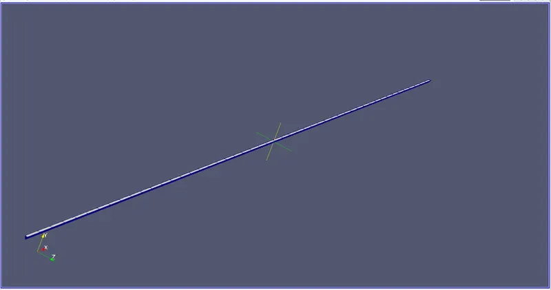
Below is the wedge boundary conditions with an angle of 45 with meshing
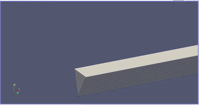
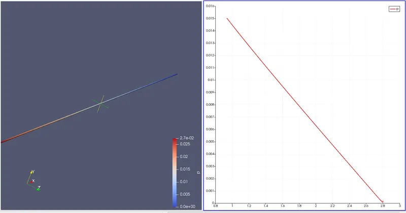
Pressure contour and pressure profile:
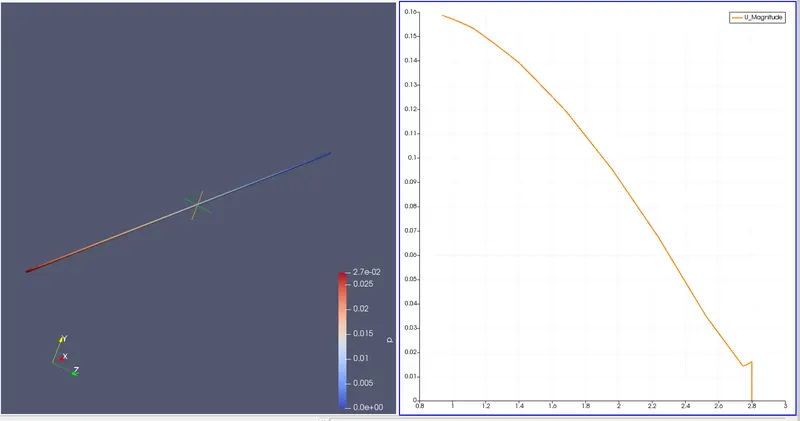
velocity contour and velocity profile:
Fully developed flow velocity profile:
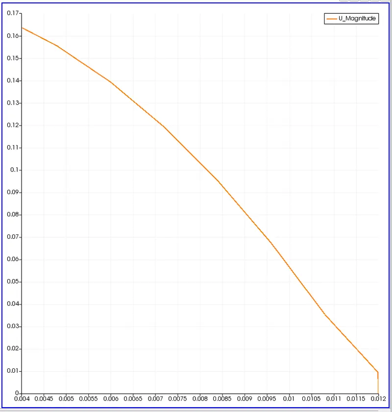
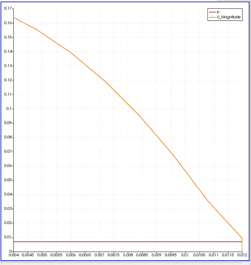
Max velocity and pressure drop for fully dedveloped flow:
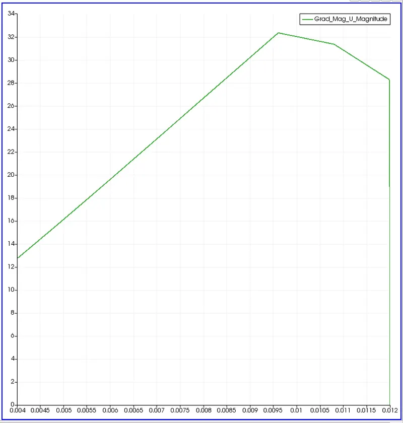
Wall shear stress for fully developed flow of the geometry:
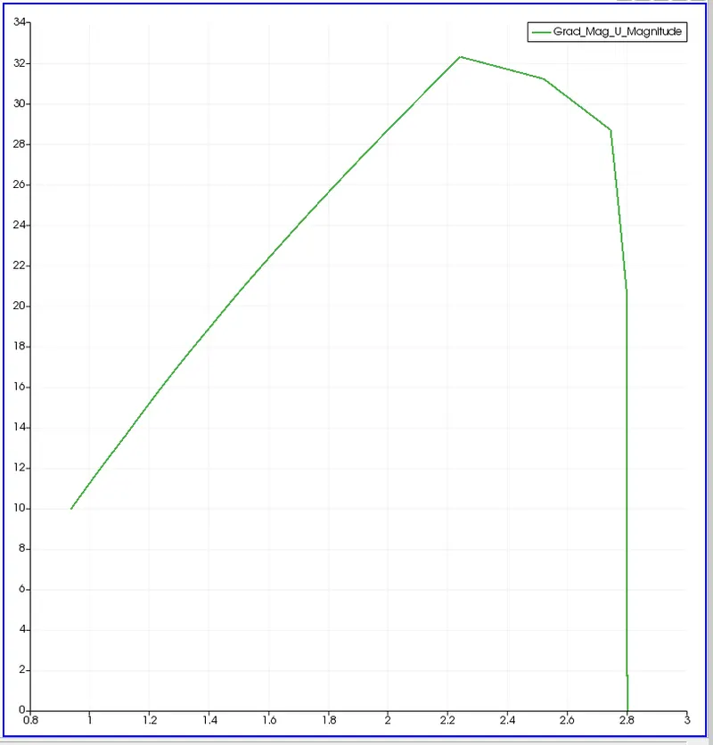
Post process shear stress for fully developed of the geometry
Now the difference of the paraview in the wedge boundary conditions:
Wedge angle 10 degress
Wedge angle 25 degrees
Wedge angle 45 degrees
Now for the Symmetry boundary conditions:
For the symmetry boundary conditions at an angle 10:
First create the code in the matlab to generate the blockMeshDict file in for the geometry of the figure with the symmetry boundary conditions at an angle 10 as shown below:
% SIMULATION OF FLOW THROUGH A PIPE
% Code to automate generation of blockMeshDict file
clear all
close all
clc


% INPUTS
% Assumptions
% Diameter of Pipe (m)
D = 0.02;

% Radius of Pipe (m)
R = D/2;

% Reynold's Number
Re = 2100;

% Wedge Angle (degrees)
theta = 10;

% Total Length of the Pipe (m)
L = 2.8;


% Assuming working fluid is water at 25° C
% Density of water (kg/m³)
rho = 997;

% Dynamic Viscosity of Water (Pa.s)
mu = 8.90 * 10^-4;

% Kinematic Viscosity of Water (m^2/s)
nu = mu/rho;


% Hydrodynamic Entrance Length (m)
L_h = 138* D;


% HAGEN - POISEUILLE'S FLOW EQUATIONS
% Average Velocity (m/s)
V_avg = (mu * Re)/(rho * D);

% Maximum Velocity (m/s)
V_max = 2 * V_avg;

% Pressure Drop (Pa)
delta_p = (32*mu*V_avg*L)/(D^2);

% Kinematic Pressure Drop (Pa)
kinematic_delta_p = delta_p/rho;

% Calculating shear stress
r = linspace(0,(D/2),100);
for i = 1:length(r)
    tau(i) = 2 * mu * V_max * abs(r(i))/R^2;
end
figure(1)

plot(r,tau)

xlabel('Radius of pipe')

ylabel('shear stress')

title('Shear stress for Symmetry Boundary condition with angle 10')

legend('shear stress')


% DEFINING THE GEOMETRY
% Vertices
V0 = [0 0 0];
V1 = [0 R*cosd(theta/2) -R*sind(theta/2)];
V2 = [0 R*cosd(theta/2) R*sind(theta/2)];

V3 = [L 0 0];
V4 = [L R*cosd(theta/2) -R*sind(theta/2)];
V5 = [L R*cosd(theta/2) R*sind(theta/2)];


% BLOCKMESHDICT FILE
% Creating the file
% Header
h1 = '/*--------------------------------*- C++ -*----------------------------------*\';
h2 = '  =========                 |';
h3 = '  \\      /  F ield         | OpenFOAM: The Open Source CFD Toolbox';
h4 = '   \\    /   O peration     | Website:  https://openfoam.org';
h5 = '    \\  /    A nd           | Version:  9';
h6 = '     \\/     M anipulation  |';
h7 = '\*---------------------------------------------------------------------------*/';
h8 = 'FoamFile';
h9 = '{';
h10 = '    format      ascii;';
h11 = '    class       dictionary;';
h12 = '    object      blockMeshDict;';
h13 = '}';
h14 = '// * * * * * * * * * * * * * * * * * * * * * * * * * * * * * * * * * * * * * //';


% Creating BlockMesh File
f1 = fopen('blockMeshDict.txt','w');

% Header
fprintf(f1,'%s\n',h1);
fprintf(f1,'%s\n',h2);
fprintf(f1,'%s\n',h3);
fprintf(f1,'%s\n',h4);
fprintf(f1,'%s\n',h5);
fprintf(f1,'%s\n',h6);
fprintf(f1,'%s\n',h7);
fprintf(f1,'%s\n',h8);
fprintf(f1,'%s\n',h9);
fprintf(f1,'%s\n',h10);
fprintf(f1,'%s\n',h11);
fprintf(f1,'%s\n',h12);
fprintf(f1,'%s\n',h13);
fprintf(f1,'%s\n\n',h14);

% Conversion Factor
fprintf(f1,'%s\n\n','convertToMeters 1;');

% Vertices
fprintf(f1,'%s\n','vertices');
fprintf(f1,'%s\n','(');
fprintf(f1,'\t(%d %d %d)\n',V0);
fprintf(f1,'\t(%d %f %f)\n',V1);
fprintf(f1,'\t(%d %f %f)\n',V2);
fprintf(f1,'\t(%.2f %d %d)\n',V3);
fprintf(f1,'\t(%.2f %f %f)\n',V4);
fprintf(f1,'\t(%.2f %f %f)\n',V5);
fprintf(f1,'%s\n\n',');');

% Blocks
fprintf(f1,'%s\n','blocks');
fprintf(f1,'%s\n','(');
fprintf(f1,'\t hex (0 3 4 1 0 3 5 2) (50 10 1) simpleGrading (1 1 1)\n');
fprintf(f1,'%s\n\n',');');

% Edges
fprintf(f1,'%s\n','edges');
fprintf(f1,'%s\n','(');
fprintf(f1,'\tarc 2 1 (%d %.3f %d)\n',0,R,0);
fprintf(f1,'\tarc 4 5 (%.3f %.3f %d)\n',L,R,0);
fprintf(f1,'%s\n\n',');');

% Boundary
fprintf(f1,'%s\n','boundary');
fprintf(f1,'%s\n','(');

% Axis
fprintf(f1,'\taxis\n');
fprintf(f1,'\t{\n');
fprintf(f1,'\t\ttype empty;\n');
fprintf(f1,'\t\tfaces\n');
fprintf(f1,'\t\t(\n');
fprintf(f1,'\t\t\t(0 3 3 0)\n');
fprintf(f1,'\t\t);\n');
fprintf(f1,'\t}\n\n');

% Inlet
fprintf(f1,'\tinlet\n');
fprintf(f1,'\t{\n');
fprintf(f1,'\t\ttype patch;\n');
fprintf(f1,'\t\tfaces\n');
fprintf(f1,'\t\t(\n');
fprintf(f1,'\t\t\t(0 2 1 0)\n');
fprintf(f1,'\t\t);\n');
fprintf(f1,'\t}\n\n');

% Outlet
fprintf(f1,'\toutlet\n');
fprintf(f1,'\t{\n');
fprintf(f1,'\t\ttype patch;\n');
fprintf(f1,'\t\tfaces\n');
fprintf(f1,'\t\t(\n');
fprintf(f1,'\t\t\t(3 4 5 3)\n');
fprintf(f1,'\t\t);\n');
fprintf(f1,'\t}\n\n');

% Front Face
fprintf(f1,'\tfront\n');
fprintf(f1,'\t{\n');
fprintf(f1,'\t\ttype symmetry;\n');
fprintf(f1,'\t\tfaces\n');
fprintf(f1,'\t\t(\n');
fprintf(f1,'\t\t\t(0 3 5 2)\n');
fprintf(f1,'\t\t);\n');
fprintf(f1,'\t}\n\n');

% Back Face
fprintf(f1,'\tback\n');
fprintf(f1,'\t{\n');
fprintf(f1,'\t\ttype symmetry;\n');
fprintf(f1,'\t\tfaces\n');
fprintf(f1,'\t\t(\n');
fprintf(f1,'\t\t\t(0 1 4 3)\n');
fprintf(f1,'\t\t);\n');
fprintf(f1,'\t}\n\n');

% Top Wall
fprintf(f1,'\tpipeWall\n');
fprintf(f1,'\t{\n');
fprintf(f1,'\t\ttype wall;\n');
fprintf(f1,'\t\tfaces\n');
fprintf(f1,'\t\t(\n');
fprintf(f1,'\t\t\t(1 2 5 4)\n');
fprintf(f1,'\t\t);\n');
fprintf(f1,'\t}\n');

fprintf(f1,'%s\n\n',');');
fprintf(f1,'%s\n','mergePatchPairs');
fprintf(f1,'%s\n','(');
fprintf(f1,'%s\n\n',');');
fprintf(f1,'%s\n','// ************************************************************************* //');
Now after running the above code we will be getting the blockMeshDict file which we have to paste in the directory of the blockMesh where we have to generate the geometry. The blockMeshDict file is shown below:
/*--------------------------------*- C++ -*----------------------------------*\
  =========                 |
  \\      /  F ield         | OpenFOAM: The Open Source CFD Toolbox
   \\    /   O peration     | Website:  https://openfoam.org
    \\  /    A nd           | Version:  9
     \\/     M anipulation  |
\*---------------------------------------------------------------------------*/
FoamFile
{
    format      ascii;
    class       dictionary;
    object      blockMeshDict;
}
// * * * * * * * * * * * * * * * * * * * * * * * * * * * * * * * * * * * * * //

convertToMeters 1;

vertices
(
	(0 0 0)
	(0 0.009962 -0.000872)
	(0 0.009962 0.000872)
	(2.80 0 0)
	(2.80 0.009962 -0.000872)
	(2.80 0.009962 0.000872)
);

blocks
(
	 hex (0 3 4 1 0 3 5 2) (50 10 1) simpleGrading (1 1 1)
);

edges
(
	arc 2 1 (0 0.010 0)
	arc 4 5 (2.800 0.010 0)
);

boundary
(
	axis
	{
		type empty;
		faces
		(
			(0 3 3 0)
		);
	}

	inlet
	{
		type patch;
		faces
		(
			(0 2 1 0)
		);
	}

	outlet
	{
		type patch;
		faces
		(
			(3 4 5 3)
		);
	}

	front
	{
		type symmetry;
		faces
		(
			(0 3 5 2)
		);
	}

	back
	{
		type symmetry;
		faces
		(
			(0 1 4 3)
		);
	}

	pipeWall
	{
		type wall;
		faces
		(
			(1 2 5 4)
		);
	}
);

mergePatchPairs
(
);

// ************************************************************************* //
Now change the values of the controlDoct file as per the requirements shown below:
/*--------------------------------*- C++ -*----------------------------------*\
  =========                 |
  \\      /  F ield         | OpenFOAM: The Open Source CFD Toolbox
   \\    /   O peration     | Website:  https://openfoam.org
    \\  /    A nd           | Version:  10
     \\/     M anipulation  |
\*---------------------------------------------------------------------------*/
FoamFile
{
    format      ascii;
    class       dictionary;
    location    "system";
    object      controlDict;
}
// * * * * * * * * * * * * * * * * * * * * * * * * * * * * * * * * * * * * * //

application     icoFoam;

startFrom       startTime;

startTime       0;

stopAt          endTime;

endTime         30;

deltaT          0.05;

writeControl    timeStep;

writeInterval   200;

purgeWrite      0;

writeFormat     ascii;

writePrecision  6;

writeCompression off;

timeFormat      general;

timePrecision   6;

runTimeModifiable true;


// ************************************************************************* //
Now change the pressure file p as shown below:
/*--------------------------------*- C++ -*----------------------------------*\
  =========                 |
  \\      /  F ield         | OpenFOAM: The Open Source CFD Toolbox
   \\    /   O peration     | Website:  https://openfoam.org
    \\  /    A nd           | Version:  10
     \\/     M anipulation  |
\*---------------------------------------------------------------------------*/
FoamFile
{
    format      ascii;
    class       volScalarField;
    object      p;
}
// * * * * * * * * * * * * * * * * * * * * * * * * * * * * * * * * * * * * * //

dimensions      [0 2 -2 0 0 0 0];

internalField   uniform 0;

boundaryField
{
    axis
    {
        type            empty;
    }

    inlet
    {
        type            zeroGradient;
    }

    outlet
    {
        type            fixedValue;
        value           uniform 0;
    }

    front
    {
        type            symmetry;
    }

    back
    {
        type            symmetry;
    }

    pipeWall
    {
        type            zeroGradient;
    }
}

// ************************************************************************* //
Now change the Velocity File U as shown below:
/*--------------------------------*- C++ -*----------------------------------*\
  =========                 |
  \\      /  F ield         | OpenFOAM: The Open Source CFD Toolbox
   \\    /   O peration     | Website:  https://openfoam.org
    \\  /    A nd           | Version:  10
     \\/     M anipulation  |
\*---------------------------------------------------------------------------*/
FoamFile
{
    format      ascii;
    class       volVectorField;
    object      U;
}
// * * * * * * * * * * * * * * * * * * * * * * * * * * * * * * * * * * * * * //

dimensions      [0 1 -1 0 0 0 0];

internalField   uniform (0 0 0);

boundaryField
{
    axis
    {
        type            empty;
    }

    inlet
    {
        type            fixedValue;
        value           uniform (0.0937 0 0);
    }

    outlet
    {
        type            zeroGradient;
    }

    front
    {
        type            symmetry;
    }

    back
    {
        type            symmetry;
    }

    pipeWall
    {
        type            noSlip;
    }
}

// ************************************************************************* //
After changing the directories as per the requiremnts in the geometry keep the physicalProperties file as it as from the previous case of the wedge boundary conditions.
After editing all the files in the directory we have to check the blockMesh and then check the mesh with the checkMesh comand then run the icoFoam after checking all of it then we can enter the paraView to check the mesh and to simulate it.
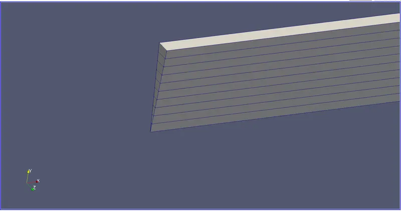
The below is the geometry of the file which we edited it through matlab code. We can see the meshing is done and the angle of the symmetry is 10 degrees.
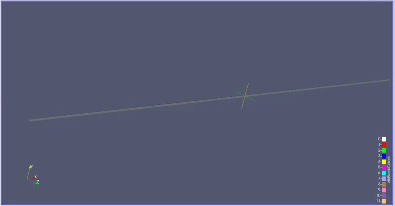
Below is the meshing of the geometry.
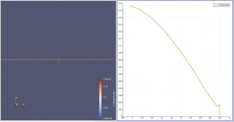
Now the velocity Contour and profile of the above geometry with an angle 10.
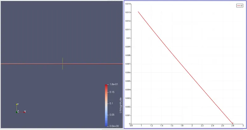
Now the pressure contour and profile of the geometry at angle 10.
Now the fully developed flow velocity profile:
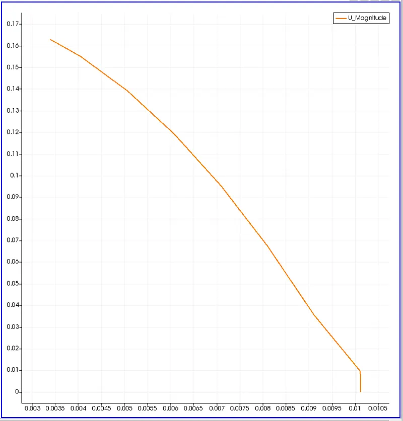
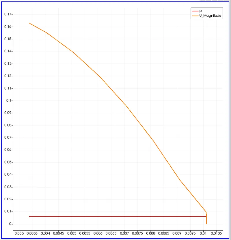
Max velocity and pressure drop for fully developed flow:
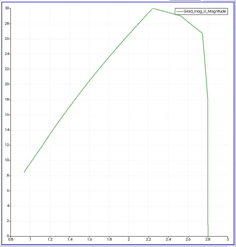
Post process shear stress :
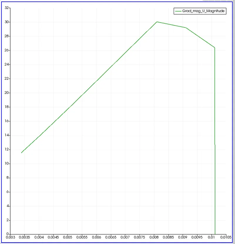
Shear stress at the wall:
Now for the symmetrical boundary Conditions at angle 25 :
By changing the angle in the MATLAB from the previous sample of the code to 25 degrees from 10 degrees and running the code we will be getting the blockMeshDict file. The MATLAB code is shown below:
% SIMULATION OF FLOW THROUGH A PIPE
% Code to automate generation of blockMeshDict file
clear all
close all
clc


% INPUTS
% Assumptions
% Diameter of Pipe (m)
D = 0.02;

% Radius of Pipe (m)
R = D/2;

% Reynold's Number
Re = 2100;

% Wedge Angle (degrees)
theta = 25;

% Total Length of the Pipe (m)
L = 2.8;


% Assuming working fluid is water at 25° C
% Density of water (kg/m³)
rho = 997;

% Dynamic Viscosity of Water (Pa.s)
mu = 8.90 * 10^-4;

% Kinematic Viscosity of Water (m^2/s)
nu = mu/rho;


% Hydrodynamic Entrance Length (m)
L_h = 138* D;


% HAGEN - POISEUILLE'S FLOW EQUATIONS
% Average Velocity (m/s)
V_avg = (mu * Re)/(rho * D);

% Maximum Velocity (m/s)
V_max = 2 * V_avg;

% Pressure Drop (Pa)
delta_p = (32*mu*V_avg*L)/(D^2);

% Kinematic Pressure Drop (Pa)
kinematic_delta_p = delta_p/rho;

% Calculating shear stress
r = linspace(0,(D/2),100);
for i = 1:length(r)
    tau(i) = 2 * mu * V_max * abs(r(i))/R^2;
end
figure(1)

plot(r,tau)

xlabel('Radius of pipe')

ylabel('shear stress')

title('Shear stress for Symmetry Boundary condition with angle 10')

legend('shear stress')


% DEFINING THE GEOMETRY
% Vertices
V0 = [0 0 0];
V1 = [0 R*cosd(theta/2) -R*sind(theta/2)];
V2 = [0 R*cosd(theta/2) R*sind(theta/2)];

V3 = [L 0 0];
V4 = [L R*cosd(theta/2) -R*sind(theta/2)];
V5 = [L R*cosd(theta/2) R*sind(theta/2)];


% BLOCKMESHDICT FILE
% Creating the file
% Header
h1 = '/*--------------------------------*- C++ -*----------------------------------*\';
h2 = '  =========                 |';
h3 = '  \\      /  F ield         | OpenFOAM: The Open Source CFD Toolbox';
h4 = '   \\    /   O peration     | Website:  https://openfoam.org';
h5 = '    \\  /    A nd           | Version:  9';
h6 = '     \\/     M anipulation  |';
h7 = '\*---------------------------------------------------------------------------*/';
h8 = 'FoamFile';
h9 = '{';
h10 = '    format      ascii;';
h11 = '    class       dictionary;';
h12 = '    object      blockMeshDict;';
h13 = '}';
h14 = '// * * * * * * * * * * * * * * * * * * * * * * * * * * * * * * * * * * * * * //';


% Creating BlockMesh File
f1 = fopen('blockMeshDict.txt','w');

% Header
fprintf(f1,'%s\n',h1);
fprintf(f1,'%s\n',h2);
fprintf(f1,'%s\n',h3);
fprintf(f1,'%s\n',h4);
fprintf(f1,'%s\n',h5);
fprintf(f1,'%s\n',h6);
fprintf(f1,'%s\n',h7);
fprintf(f1,'%s\n',h8);
fprintf(f1,'%s\n',h9);
fprintf(f1,'%s\n',h10);
fprintf(f1,'%s\n',h11);
fprintf(f1,'%s\n',h12);
fprintf(f1,'%s\n',h13);
fprintf(f1,'%s\n\n',h14);

% Conversion Factor
fprintf(f1,'%s\n\n','convertToMeters 1;');

% Vertices
fprintf(f1,'%s\n','vertices');
fprintf(f1,'%s\n','(');
fprintf(f1,'\t(%d %d %d)\n',V0);
fprintf(f1,'\t(%d %f %f)\n',V1);
fprintf(f1,'\t(%d %f %f)\n',V2);
fprintf(f1,'\t(%.2f %d %d)\n',V3);
fprintf(f1,'\t(%.2f %f %f)\n',V4);
fprintf(f1,'\t(%.2f %f %f)\n',V5);
fprintf(f1,'%s\n\n',');');

% Blocks
fprintf(f1,'%s\n','blocks');
fprintf(f1,'%s\n','(');
fprintf(f1,'\t hex (0 3 4 1 0 3 5 2) (50 10 1) simpleGrading (1 1 1)\n');
fprintf(f1,'%s\n\n',');');

% Edges
fprintf(f1,'%s\n','edges');
fprintf(f1,'%s\n','(');
fprintf(f1,'\tarc 2 1 (%d %.3f %d)\n',0,R,0);
fprintf(f1,'\tarc 4 5 (%.3f %.3f %d)\n',L,R,0);
fprintf(f1,'%s\n\n',');');

% Boundary
fprintf(f1,'%s\n','boundary');
fprintf(f1,'%s\n','(');

% Axis
fprintf(f1,'\taxis\n');
fprintf(f1,'\t{\n');
fprintf(f1,'\t\ttype empty;\n');
fprintf(f1,'\t\tfaces\n');
fprintf(f1,'\t\t(\n');
fprintf(f1,'\t\t\t(0 3 3 0)\n');
fprintf(f1,'\t\t);\n');
fprintf(f1,'\t}\n\n');

% Inlet
fprintf(f1,'\tinlet\n');
fprintf(f1,'\t{\n');
fprintf(f1,'\t\ttype patch;\n');
fprintf(f1,'\t\tfaces\n');
fprintf(f1,'\t\t(\n');
fprintf(f1,'\t\t\t(0 2 1 0)\n');
fprintf(f1,'\t\t);\n');
fprintf(f1,'\t}\n\n');

% Outlet
fprintf(f1,'\toutlet\n');
fprintf(f1,'\t{\n');
fprintf(f1,'\t\ttype patch;\n');
fprintf(f1,'\t\tfaces\n');
fprintf(f1,'\t\t(\n');
fprintf(f1,'\t\t\t(3 4 5 3)\n');
fprintf(f1,'\t\t);\n');
fprintf(f1,'\t}\n\n');

% Front Face
fprintf(f1,'\tfront\n');
fprintf(f1,'\t{\n');
fprintf(f1,'\t\ttype symmetry;\n');
fprintf(f1,'\t\tfaces\n');
fprintf(f1,'\t\t(\n');
fprintf(f1,'\t\t\t(0 3 5 2)\n');
fprintf(f1,'\t\t);\n');
fprintf(f1,'\t}\n\n');

% Back Face
fprintf(f1,'\tback\n');
fprintf(f1,'\t{\n');
fprintf(f1,'\t\ttype symmetry;\n');
fprintf(f1,'\t\tfaces\n');
fprintf(f1,'\t\t(\n');
fprintf(f1,'\t\t\t(0 1 4 3)\n');
fprintf(f1,'\t\t);\n');
fprintf(f1,'\t}\n\n');

% Top Wall
fprintf(f1,'\tpipeWall\n');
fprintf(f1,'\t{\n');
fprintf(f1,'\t\ttype wall;\n');
fprintf(f1,'\t\tfaces\n');
fprintf(f1,'\t\t(\n');
fprintf(f1,'\t\t\t(1 2 5 4)\n');
fprintf(f1,'\t\t);\n');
fprintf(f1,'\t}\n');

fprintf(f1,'%s\n\n',');');
fprintf(f1,'%s\n','mergePatchPairs');
fprintf(f1,'%s\n','(');
fprintf(f1,'%s\n\n',');');
fprintf(f1,'%s\n','// ************************************************************************* //');
From running this code we will be getting the blockMeshDict file which we have to paste in the in blockMeshDict directory. The blockMeshDict file is shown below:
/*--------------------------------*- C++ -*----------------------------------*\
  =========                 |
  \\      /  F ield         | OpenFOAM: The Open Source CFD Toolbox
   \\    /   O peration     | Website:  https://openfoam.org
    \\  /    A nd           | Version:  9
     \\/     M anipulation  |
\*---------------------------------------------------------------------------*/
FoamFile
{
    format      ascii;
    class       dictionary;
    object      blockMeshDict;
}
// * * * * * * * * * * * * * * * * * * * * * * * * * * * * * * * * * * * * * //

convertToMeters 1;

vertices
(
	(0 0 0)
	(0 0.009763 -0.002164)
	(0 0.009763 0.002164)
	(2.80 0 0)
	(2.80 0.009763 -0.002164)
	(2.80 0.009763 0.002164)
);

blocks
(
	 hex (0 3 4 1 0 3 5 2) (50 10 1) simpleGrading (1 1 1)
);

edges
(
	arc 2 1 (0 0.010 0)
	arc 4 5 (2.800 0.010 0)
);

boundary
(
	axis
	{
		type empty;
		faces
		(
			(0 3 3 0)
		);
	}

	inlet
	{
		type patch;
		faces
		(
			(0 2 1 0)
		);
	}

	outlet
	{
		type patch;
		faces
		(
			(3 4 5 3)
		);
	}

	front
	{
		type symmetry;
		faces
		(
			(0 3 5 2)
		);
	}

	back
	{
		type symmetry;
		faces
		(
			(0 1 4 3)
		);
	}

	pipeWall
	{
		type wall;
		faces
		(
			(1 2 5 4)
		);
	}
);

mergePatchPairs
(
);

// ************************************************************************* //
Keeping the remaining directories same from the previous one we and checking the mesh.
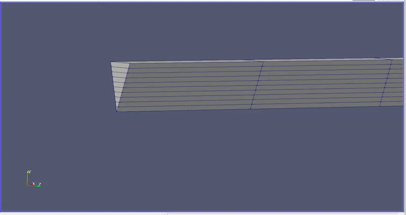
The below is the geometry of the file which we edited it through matlab code. We can see the meshing is done and the angle of the symmetry is 25 degrees.
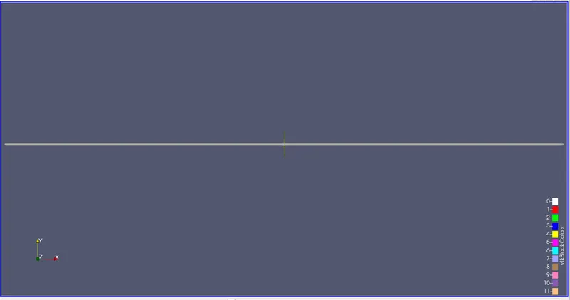
The angle of 25 with meshing is shown below:
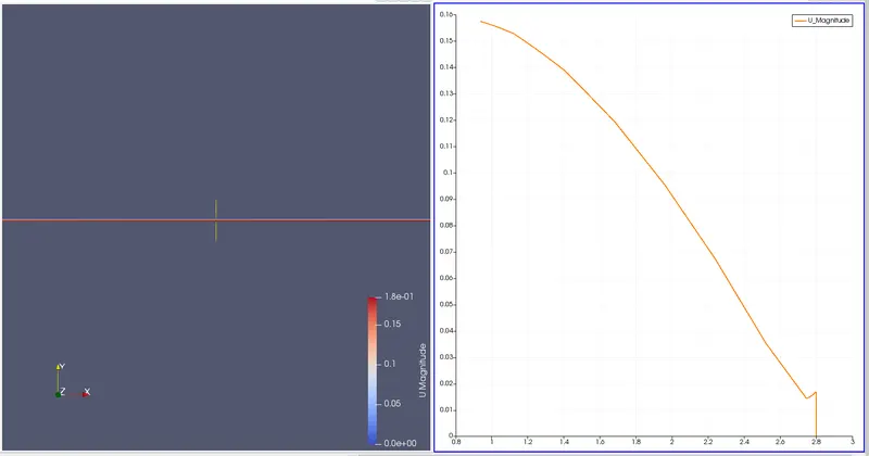
Now the velocity profile and contour of the geometry:
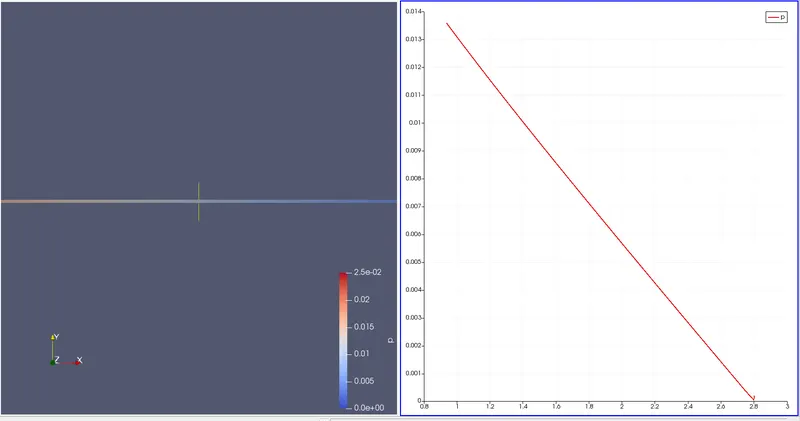
Now the pressure profile and contour of the geometry:
Now fully developed velocity profile:
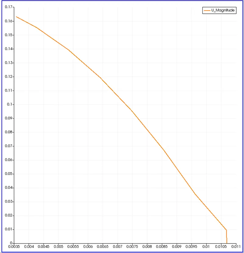
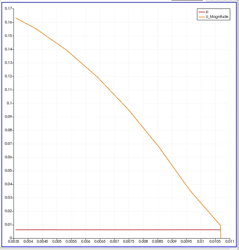
Now max velocity and pressure dropn for the fully developed flow:
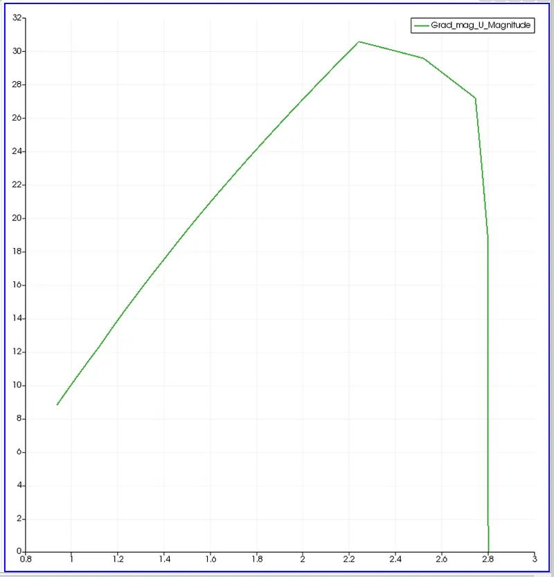
Post proces shear stress :
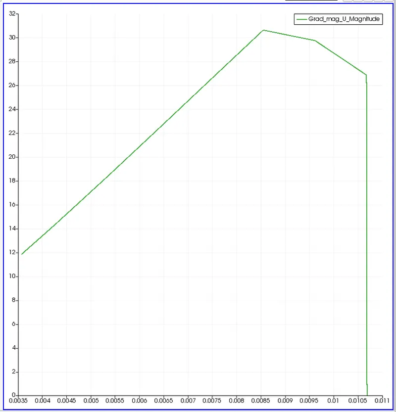
Wall shear stress:
For symmetry boundary conditions at an angle of 45:
By changing the angle in the MATLAB from the previous sample of the code to 45 degrees from 10 degrees and running the code we will be getting the blockMeshDict file. The MATLAB code is shown below:
% SIMULATION OF FLOW THROUGH A PIPE
% Code to automate generation of blockMeshDict file
clear all
close all
clc


% INPUTS
% Assumptions
% Diameter of Pipe (m)
D = 0.02;

% Radius of Pipe (m)
R = D/2;

% Reynold's Number
Re = 2100;

% Wedge Angle (degrees)
theta = 45;

% Total Length of the Pipe (m)
L = 2.8;


% Assuming working fluid is water at 25° C
% Density of water (kg/m³)
rho = 997;

% Dynamic Viscosity of Water (Pa.s)
mu = 8.90 * 10^-4;

% Kinematic Viscosity of Water (m^2/s)
nu = mu/rho;


% Hydrodynamic Entrance Length (m)
L_h = 138* D;


% HAGEN - POISEUILLE'S FLOW EQUATIONS
% Average Velocity (m/s)
V_avg = (mu * Re)/(rho * D);

% Maximum Velocity (m/s)
V_max = 2 * V_avg;

% Pressure Drop (Pa)
delta_p = (32*mu*V_avg*L)/(D^2);

% Kinematic Pressure Drop (Pa)
kinematic_delta_p = delta_p/rho;

% Calculating shear stress
r = linspace(0,(D/2),100);
for i = 1:length(r)
    tau(i) = 2 * mu * V_max * abs(r(i))/R^2;
end
figure(1)

plot(r,tau)

xlabel('Radius of pipe')

ylabel('shear stress')

title('Shear stress for Symmetry Boundary condition with angle 10')

legend('shear stress')


% DEFINING THE GEOMETRY
% Vertices
V0 = [0 0 0];
V1 = [0 R*cosd(theta/2) -R*sind(theta/2)];
V2 = [0 R*cosd(theta/2) R*sind(theta/2)];

V3 = [L 0 0];
V4 = [L R*cosd(theta/2) -R*sind(theta/2)];
V5 = [L R*cosd(theta/2) R*sind(theta/2)];


% BLOCKMESHDICT FILE
% Creating the file
% Header
h1 = '/*--------------------------------*- C++ -*----------------------------------*\';
h2 = '  =========                 |';
h3 = '  \\      /  F ield         | OpenFOAM: The Open Source CFD Toolbox';
h4 = '   \\    /   O peration     | Website:  https://openfoam.org';
h5 = '    \\  /    A nd           | Version:  9';
h6 = '     \\/     M anipulation  |';
h7 = '\*---------------------------------------------------------------------------*/';
h8 = 'FoamFile';
h9 = '{';
h10 = '    format      ascii;';
h11 = '    class       dictionary;';
h12 = '    object      blockMeshDict;';
h13 = '}';
h14 = '// * * * * * * * * * * * * * * * * * * * * * * * * * * * * * * * * * * * * * //';


% Creating BlockMesh File
f1 = fopen('blockMeshDict.txt','w');

% Header
fprintf(f1,'%s\n',h1);
fprintf(f1,'%s\n',h2);
fprintf(f1,'%s\n',h3);
fprintf(f1,'%s\n',h4);
fprintf(f1,'%s\n',h5);
fprintf(f1,'%s\n',h6);
fprintf(f1,'%s\n',h7);
fprintf(f1,'%s\n',h8);
fprintf(f1,'%s\n',h9);
fprintf(f1,'%s\n',h10);
fprintf(f1,'%s\n',h11);
fprintf(f1,'%s\n',h12);
fprintf(f1,'%s\n',h13);
fprintf(f1,'%s\n\n',h14);

% Conversion Factor
fprintf(f1,'%s\n\n','convertToMeters 1;');

% Vertices
fprintf(f1,'%s\n','vertices');
fprintf(f1,'%s\n','(');
fprintf(f1,'\t(%d %d %d)\n',V0);
fprintf(f1,'\t(%d %f %f)\n',V1);
fprintf(f1,'\t(%d %f %f)\n',V2);
fprintf(f1,'\t(%.2f %d %d)\n',V3);
fprintf(f1,'\t(%.2f %f %f)\n',V4);
fprintf(f1,'\t(%.2f %f %f)\n',V5);
fprintf(f1,'%s\n\n',');');

% Blocks
fprintf(f1,'%s\n','blocks');
fprintf(f1,'%s\n','(');
fprintf(f1,'\t hex (0 3 4 1 0 3 5 2) (50 10 1) simpleGrading (1 1 1)\n');
fprintf(f1,'%s\n\n',');');

% Edges
fprintf(f1,'%s\n','edges');
fprintf(f1,'%s\n','(');
fprintf(f1,'\tarc 2 1 (%d %.3f %d)\n',0,R,0);
fprintf(f1,'\tarc 4 5 (%.3f %.3f %d)\n',L,R,0);
fprintf(f1,'%s\n\n',');');

% Boundary
fprintf(f1,'%s\n','boundary');
fprintf(f1,'%s\n','(');

% Axis
fprintf(f1,'\taxis\n');
fprintf(f1,'\t{\n');
fprintf(f1,'\t\ttype empty;\n');
fprintf(f1,'\t\tfaces\n');
fprintf(f1,'\t\t(\n');
fprintf(f1,'\t\t\t(0 3 3 0)\n');
fprintf(f1,'\t\t);\n');
fprintf(f1,'\t}\n\n');

% Inlet
fprintf(f1,'\tinlet\n');
fprintf(f1,'\t{\n');
fprintf(f1,'\t\ttype patch;\n');
fprintf(f1,'\t\tfaces\n');
fprintf(f1,'\t\t(\n');
fprintf(f1,'\t\t\t(0 2 1 0)\n');
fprintf(f1,'\t\t);\n');
fprintf(f1,'\t}\n\n');

% Outlet
fprintf(f1,'\toutlet\n');
fprintf(f1,'\t{\n');
fprintf(f1,'\t\ttype patch;\n');
fprintf(f1,'\t\tfaces\n');
fprintf(f1,'\t\t(\n');
fprintf(f1,'\t\t\t(3 4 5 3)\n');
fprintf(f1,'\t\t);\n');
fprintf(f1,'\t}\n\n');

% Front Face
fprintf(f1,'\tfront\n');
fprintf(f1,'\t{\n');
fprintf(f1,'\t\ttype symmetry;\n');
fprintf(f1,'\t\tfaces\n');
fprintf(f1,'\t\t(\n');
fprintf(f1,'\t\t\t(0 3 5 2)\n');
fprintf(f1,'\t\t);\n');
fprintf(f1,'\t}\n\n');

% Back Face
fprintf(f1,'\tback\n');
fprintf(f1,'\t{\n');
fprintf(f1,'\t\ttype symmetry;\n');
fprintf(f1,'\t\tfaces\n');
fprintf(f1,'\t\t(\n');
fprintf(f1,'\t\t\t(0 1 4 3)\n');
fprintf(f1,'\t\t);\n');
fprintf(f1,'\t}\n\n');

% Top Wall
fprintf(f1,'\tpipeWall\n');
fprintf(f1,'\t{\n');
fprintf(f1,'\t\ttype wall;\n');
fprintf(f1,'\t\tfaces\n');
fprintf(f1,'\t\t(\n');
fprintf(f1,'\t\t\t(1 2 5 4)\n');
fprintf(f1,'\t\t);\n');
fprintf(f1,'\t}\n');

fprintf(f1,'%s\n\n',');');
fprintf(f1,'%s\n','mergePatchPairs');
fprintf(f1,'%s\n','(');
fprintf(f1,'%s\n\n',');');
fprintf(f1,'%s\n','// ************************************************************************* //');
After running the file we will bw fetting the blockMeshDict file which we have to paste in in the directory to create geometry. The blockMeshDict file is shown below:
/*--------------------------------*- C++ -*----------------------------------*\
  =========                 |
  \\      /  F ield         | OpenFOAM: The Open Source CFD Toolbox
   \\    /   O peration     | Website:  https://openfoam.org
    \\  /    A nd           | Version:  9
     \\/     M anipulation  |
\*---------------------------------------------------------------------------*/
FoamFile
{
    format      ascii;
    class       dictionary;
    object      blockMeshDict;
}
// * * * * * * * * * * * * * * * * * * * * * * * * * * * * * * * * * * * * * //

convertToMeters 1;

vertices
(
	(0 0 0)
	(0 0.009239 -0.003827)
	(0 0.009239 0.003827)
	(2.80 0 0)
	(2.80 0.009239 -0.003827)
	(2.80 0.009239 0.003827)
);

blocks
(
	 hex (0 3 4 1 0 3 5 2) (50 10 1) simpleGrading (1 1 1)
);

edges
(
	arc 2 1 (0 0.010 0)
	arc 4 5 (2.800 0.010 0)
);

boundary
(
	axis
	{
		type empty;
		faces
		(
			(0 3 3 0)
		);
	}

	inlet
	{
		type patch;
		faces
		(
			(0 2 1 0)
		);
	}

	outlet
	{
		type patch;
		faces
		(
			(3 4 5 3)
		);
	}

	front
	{
		type symmetry;
		faces
		(
			(0 3 5 2)
		);
	}

	back
	{
		type symmetry;
		faces
		(
			(0 1 4 3)
		);
	}

	pipeWall
	{
		type wall;
		faces
		(
			(1 2 5 4)
		);
	}
);

mergePatchPairs
(
);

// ************************************************************************* //
Keeping the remaining directories same from the previous one we and checking the mesh.
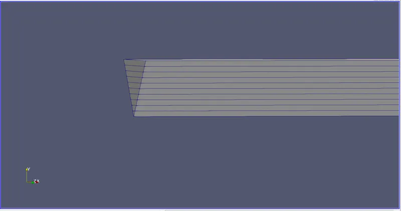
The below is the geometry of the file which we edited it through matlab code. We can see the meshing is done and the angle of the symmetry is 45 degrees.
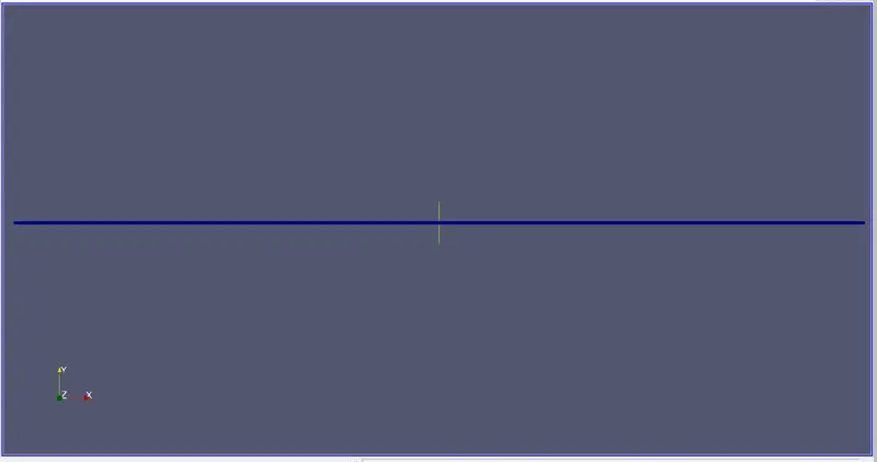
Now the with the symmetric angle 45 and with the mesh.
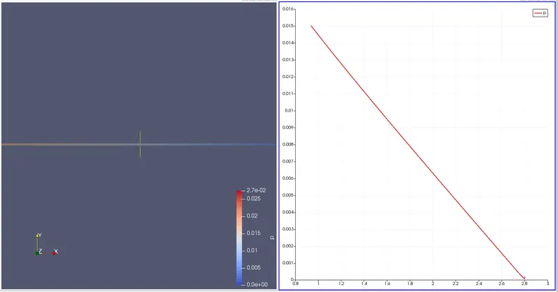
The pressure contour and the profile:
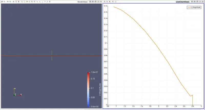
Velocity contour and the profile:
Fully developed flow velocity profile:
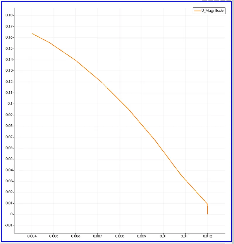
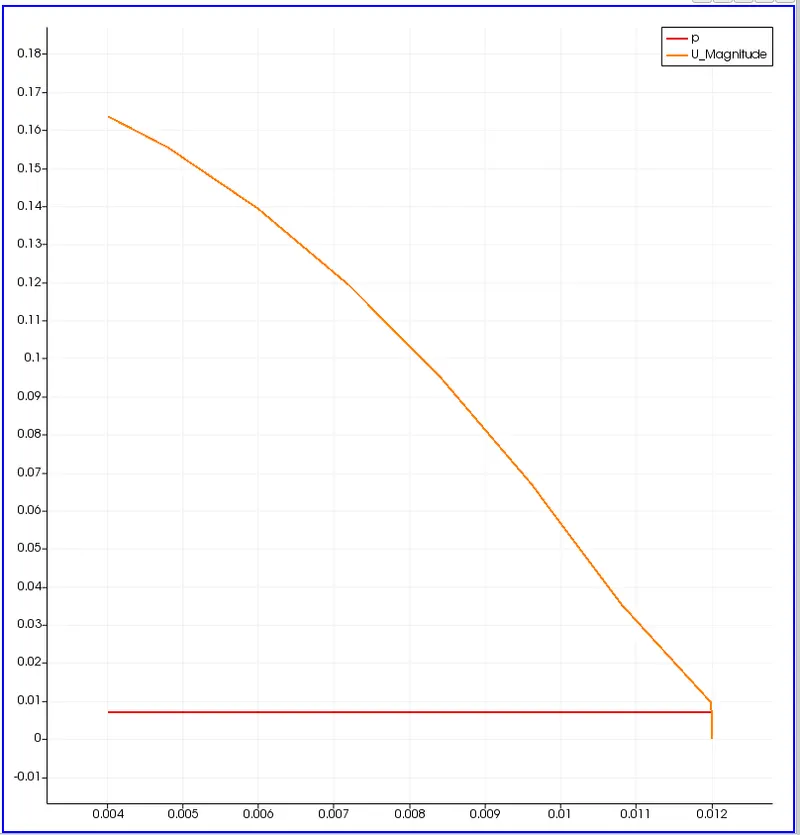
Max velocity and pressure drop for fully developed flow :
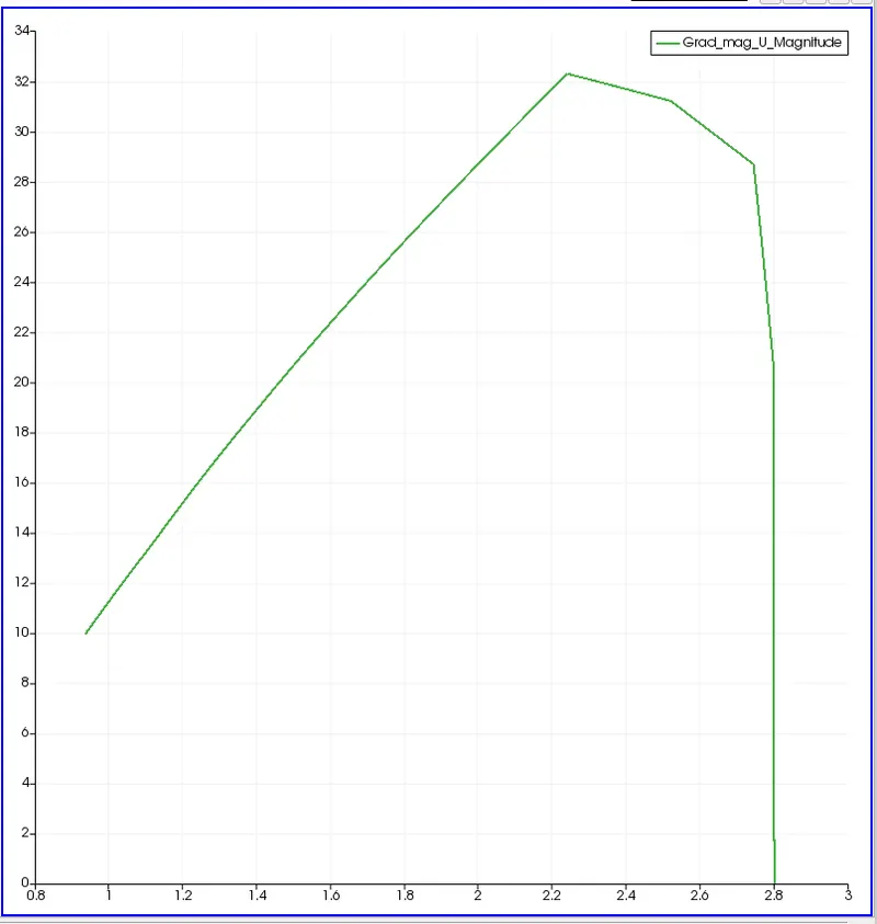
Post Process shear stress:
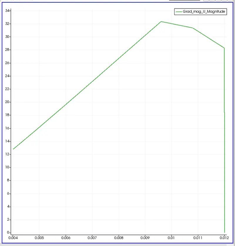
Wall shear stress profile:
Now the differences of geometry in each and every symmetric boundary conditions
At an angle of 10 degrees:
At an angle of 25 degress:
at angle of 45 degrees:
The analytical shear stress profile has been attached with the document from which we can see that the analytical profile gradually increases and keeps on increasing and for the fully developed profile it first increses and then abruptly decreases.