Week 12 - Validation studies of Symmetry BC vs Wedge BC in OpenFOAM vs Analytical H.P equation
AIM:
- To write a program in matlab that can generate the mesh automatically for any wedge angle, diameter and length of pipe.
- To validate maximum velocity and pressure drop for fully developed flow.
- To post process shear stress for fully developed flow.
HAGEN-POISEUILLE EQUATION:
Hagen Poiseuille equation is a physical law that gives the pressure drop in an incompressible and newtonian fluid in laminar flow flowing through a long cylindrical pipe of constant cross section. The equation is obtained from navier-stokes equation.
ASSUMPTION:
- The flow is steady and laminar.
- The flow is incompressible and Newtonian.
- The flow is axisymmetric.
- The flow is fully developed.
Hagen–Poiseuille flow implies not just the relation for the pressure drop, above, but also the full solution for the laminar flow profile, which is parabolic. However, the result for the pressure drop can be extended to turbulent flow by inferring an effective turbulent viscosity in the case of turbulent flow, even though the flow profile in turbulent flow is strictly speaking not actually parabolic. In both cases, laminar or turbulent, the pressure drop is related to the stress at the wall, which determines the so-called friction factor. The wall stress can be determined phenomenologically by the darcy-weisbach equation in the field of hydraulics, given a relationship for the friction factor in terms of the Reynolds number.
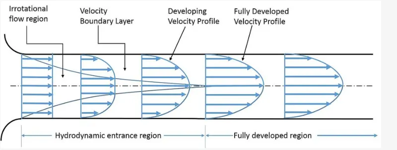
The region from the inlet of pipe to the point, at which the velocity profile is fully developed is called hydrodynamic entry region.
Fully developed flow means that velocity doesnot change in the fluid flow direction.
Let us consider that fluid flowing through pipe is water,
Diameter of pipe = 0.02m
Property of water at 30c and 1 atm,
|
PROPERTY |
VALUE |
|
density |
996 kg/m^3 |
|
Dynamic viscosity |
0.799*10^-3 Ns/m^2 |
|
Kinematic viscosity |
8.007*10^-7 m^2/s |
VELOCITY CALCULATION:
Average velocity = Re*mu/rho*D = (2100*7.99E-4)/(996*0.02) = 0.08 m/s
Expected maximum velocity = 2*average velocity = 2*0.08 = 0.164 m/s
HYDRODYNAMIC ENTRANCE LENGTH:
L_e = 0.06*Re*D = 0.06*2100*0.02 = 2.52m
TOTAL LENGTH:
L = 2.52 +1 = 3.52 m
PRESSURE DROP:
Delta p = (32*mu*L*v_(avg))/D^2
Delta p = (32*0.799e-3*3.52*0.08)/0.02^2 = 17.99 pa.
Kinematic pressure drop = delta p/rho = 17.99/996 = 0.018 m^2/s^2
CASE 1: WEDGE BOUNDARY CONDITIONS
MATLAB CODE:
MATLAB CODE TO GENERATE BLOCKMESHDICT FILE:
clear all
close all
clc

%reynolds number
re = 2100;

%total length
l = input('length of the pipe : ');

%density
rho = 996;

%viscosity
mu = 0.799e-3;

%diameter
D = input('diameter of pipe : ');

%radius
r = D/2;

%entrance length
l_e = 0.06*D*re;

%angle
theta = input('wedge angle : ');

%simple grading
nx = 200;
ny = 20;
nz = 1;

%average velocity
v_avg = (re*mu)/(rho*D);

%maximum velocity
v_max = 2*v_avg;

%pressure drop
delta_p = (32*mu*l*v_avg)/(D^2);

%kinematic pressure drop
kin_p = (delta_p)/rho;

%creating blockmeshdict file
h1 = '/*-------------------------------*- c++ -*-------------------------------------*\';
h2 = '   =========                  |                                                  ';
h3 = '   \\      /   F ield         |  OpenFOAM: The Open Source CFD Toolbox           ';
h4 = '    \\    /    O peration     |  Website:  https://openfoam.org                  ';
h5 = '     \\  /     A nd           |  Version:  8                                     ';
h6 = '      \\/      M anipulation  |                                                  ';
h7 = '\*-----------------------------------------------------------------------------*/';
h8 = 'FoamFile';
h15 = '//*****************************************************************************//';

%opening the file
f1 = fopen('blockMeshDict.txt','w');

%writing comments
fprintf(f1,'%s\n',h1);
fprintf(f1,'%s\n',h2);
fprintf(f1,'%s\n',h3);
fprintf(f1,'%s\n',h4);
fprintf(f1,'%s\n',h5);
fprintf(f1,'%s\n',h6);
fprintf(f1,'%s\n',h7);

fprintf(f1,'%s\n',h8);
fprintf(f1,'{\n');
fprintf(f1,'%10s\t 2.0;\n','version');
fprintf(f1,'%9s\t ascii;\n','format');
fprintf(f1,'%8s\t dictionary;\n','class');
fprintf(f1,'%9s\t blockMeshDict;\n','object');
fprintf(f1,'}\n');
fprintf(f1,'%s\n\n',h15);

%creating conversion
fprintf(f1,'convertToMeters  1;\n\n');

%creating vertices
fprintf(f1,'vertices\n');
fprintf(f1,'(\n');
fprintf(f1,'\t (%d %d %d)\n',0,0,0);
fprintf(f1,'\t (%d %d %d)\n',0,r*cosd(theta/2),r*sind(theta/2));
fprintf(f1,'\t (%d %d %d)\n',0,r*cosd(theta/2),-r*sind(theta/2));
fprintf(f1,'\t (%d %d %d)\n',l,0,0);
fprintf(f1,'\t (%d %d %d)\n',l,r*cosd(theta/2),r*sind(theta/2));
fprintf(f1,'\t (%d %d %d)\n',l,r*cosd(theta/2),-r*sind(theta/2));
fprintf(f1,');\n\n');

%creating blocks
fprintf(f1,'blocks\n');
fprintf(f1,'(\n');
fprintf(f1,'\t hex (0 3 5 2 0 3 4 1)(%d %d %d) simpleGrading(1 0.2 1)\n',nx,ny,nz);
fprintf(f1,');\n\n');

%creating edges
fprintf(f1,'edges\n');
fprintf(f1,'(\n');
fprintf(f1,'\t arc 1 2 (%f %f %f)\n',0,r,0);
fprintf(f1,'\t arc 4 5 (%f %f %f)\n',l,r,0);
fprintf(f1,');\n\n');

%creating boundary
fprintf(f1,'boundary\n');
fprintf(f1,'(\n');

%inlet
fprintf(f1,'\t inlet\n');
fprintf(f1,'\t {\n');
fprintf(f1,'\t\t type patch;\n');
fprintf(f1,'\t\t faces\n');
fprintf(f1,'\t\t (\n');
fprintf(f1,'\t\t\t (0 1 2 0)\n');
fprintf(f1,'\t\t );\n');
fprintf(f1,'\t }\n');

%outlet
fprintf(f1,'\t outlet\n');
fprintf(f1,'\t {\n');
fprintf(f1,'\t\t type patch;\n');
fprintf(f1,'\t\t faces\n');
fprintf(f1,'\t\t (\n');
fprintf(f1,'\t\t\t (3 5 4 3)\n');
fprintf(f1,'\t\t );\n');
fprintf(f1,'\t }\n');

%top
fprintf(f1,'\t top\n');
fprintf(f1,'\t {\n');
fprintf(f1,'\t\t type wall;\n');
fprintf(f1,'\t\t faces\n');
fprintf(f1,'\t\t (\n');
fprintf(f1,'\t\t\t (1 4 5 2)\n');
fprintf(f1,'\t\t );\n');
fprintf(f1,'\t }\n');

%back
fprintf(f1,'\t back\n');
fprintf(f1,'\t {\n');
fprintf(f1,'\t\t type wedge;\n');
fprintf(f1,'\t\t faces\n');
fprintf(f1,'\t\t (\n');
fprintf(f1,'\t\t\t (0 2 5 3)\n');
fprintf(f1,'\t\t );\n');
fprintf(f1,'\t }\n');

%front
fprintf(f1,'\t front\n');
fprintf(f1,'\t {\n');
fprintf(f1,'\t\t type wedge;\n');
fprintf(f1,'\t\t faces\n');
fprintf(f1,'\t\t (\n');
fprintf(f1,'\t\t\t (0 3 4 1)\n');
fprintf(f1,'\t\t );\n');
fprintf(f1,'\t }\n');

%axis
fprintf(f1,'\t axis\n');
fprintf(f1,'\t {\n');
fprintf(f1,'\t\t type empty;\n');
fprintf(f1,'\t\t faces\n');
fprintf(f1,'\t\t (\n');
fprintf(f1,'\t\t\t (0 3 3 0)\n');
fprintf(f1,'\t\t );\n');
fprintf(f1,'\t }\n');
fprintf(f1,');\n\n');

%creating merge patch pairs
fprintf(f1,'mergePatchPairs\n(\n');
fprintf(f1,');\n');

fprintf(f1,'%s',h15);

%closing the file
fclose(f1)
MATLAB CODE:
- The above matlab code takes the user defined wedge angle and uses that angle to calculate the vertices for the mesh.
- The entrance length is calculated and 1m is added to the value so as to observe the fully developed flow.
- The file blockMeshDict.txt file is created and is write format.
- The block is defined and the mesh refinement is done by using simple grading.
- The edges is also defined.
- The boundary conditions are defined for inlet, outlet, top, bottom and axis.
BLOCKMESHDICT FILE FOR WEDGE ANGLE 10:
/*-------------------------------*- c++ -*-------------------------------------*\
   =========                  |
   \\      /   F ield         |  OpenFOAM: The Open Source CFD Toolbox
    \\    /    O peration     |  Website:  https://openfoam.org
     \\  /     A nd           |  Version:  8
      \\/      M anipulation  |
\*-----------------------------------------------------------------------------*/
FoamFile
{
   version	 2.0;
   format	 ascii;
   class	 dictionary;
   object	 blockMeshDict;
}
//*****************************************************************************//

convertToMeters  1;

vertices
(
	 (0 0 0)
	 (0 9.961947e-03 8.715574e-04)
	 (0 9.961947e-03 -8.715574e-04)
	 (3.520000e+00 0 0)
	 (3.520000e+00 9.961947e-03 8.715574e-04)
	 (3.520000e+00 9.961947e-03 -8.715574e-04)
);

blocks
(
	 hex (0 3 5 2 0 3 4 1)(200 20 1) simpleGrading(1 0.2 1)
);

edges
(
	 arc 1 2 (0.000000 0.010000 0.000000)
	 arc 4 5 (3.520000 0.010000 0.000000)
);

boundary
(
	 inlet
	 {
		 type patch;
		 faces
		 (
			 (0 1 2 0)
		 );
	 }
	 outlet
	 {
		 type patch;
		 faces
		 (
			 (3 5 4 3)
		 );
	 }
	 top
	 {
		 type wall;
		 faces
		 (
			 (1 4 5 2)
		 );
	 }
	 back
	 {
		 type wedge;
		 faces
		 (
			 (0 2 5 3)
		 );
	 }
	 front
	 {
		 type wedge;
		 faces
		 (
			 (0 3 4 1)
		 );
	 }
	 axis
	 {
		 type empty;
		 faces
		 (
			 (0 3 3 0)
		 );
	 }
);

mergePatchPairs
(
);
//*****************************************************************************//
here the geometry is created and the mesh refinement is done using grading factor.
CONTROLDICT FILE:
/*--------------------------------*- C++ -*----------------------------------*\
  =========                 |
  \\      /  F ield         | OpenFOAM: The Open Source CFD Toolbox
   \\    /   O peration     | Website:  https://openfoam.org
    \\  /    A nd           | Version:  8
     \\/     M anipulation  |
\*---------------------------------------------------------------------------*/
FoamFile
{
    version     2.0;
    format      ascii;
    class       dictionary;
    location    "system";
    object      controlDict;
}
// * * * * * * * * * * * * * * * * * * * * * * * * * * * * * * * * * * * * * //

application     icoFoam;

startFrom       startTime;

startTime       0;

stopAt          endTime;

endTime         50;

deltaT          0.01;

writeControl    timeStep;

writeInterval   20;

purgeWrite      0;

writeFormat     ascii;

writePrecision  6;

writeCompression off;

timeFormat      general;

timePrecision   6;

runTimeModifiable true;
// ************************************************************************* //
The type of solver and the start and end time of simulation is defined in this file.
TRANSPORT PROPERTIES:
/*--------------------------------*- C++ -*----------------------------------*\
  =========                 |
  \\      /  F ield         | OpenFOAM: The Open Source CFD Toolbox
   \\    /   O peration     | Website:  https://openfoam.org
    \\  /    A nd           | Version:  8
     \\/     M anipulation  |
\*---------------------------------------------------------------------------*/
FoamFile
{
    version     2.0;
    format      ascii;
    class       dictionary;
    location    "constant";
    object      transportProperties;
}
// * * * * * * * * * * * * * * * * * * * * * * * * * * * * * * * * * * * * * //

nu              [0 2 -1 0 0 0 0] 8.02e-7;


// ************************************************************************* //
kinematic viscosity of water at 30 celcius is 8.02e-7
INITIAL CONDITIONS:
PRESSURE:
/*--------------------------------*- C++ -*----------------------------------*\
  =========                 |
  \\      /  F ield         | OpenFOAM: The Open Source CFD Toolbox
   \\    /   O peration     | Website:  https://openfoam.org
    \\  /    A nd           | Version:  8
     \\/     M anipulation  |
\*---------------------------------------------------------------------------*/
FoamFile
{
    version     2.0;
    format      ascii;
    class       volScalarField;
    object      p;
}
// * * * * * * * * * * * * * * * * * * * * * * * * * * * * * * * * * * * * * //

dimensions      [0 2 -2 0 0 0 0];

internalField   uniform 0;

boundaryField
{
    inlet
    {
        type            zeroGradient;
    }

    outlet
    {
        type            fixedValue;
        value           uniform 0;
    }

    topwall
    {
        type            zeroGradient;
    }

    back
    {
        type            wedge;
    }

    front
    {
        type            wedge;
    }

    axis
    {
        type            empty;
    }
}

// ************************************************************************* //
In this file we are fixing the outlet initial conditions as a fixed value because we assume pressure at the pipe outlet to be normal air pressure which is measured as 0.
VELOCITY:
/*--------------------------------*- C++ -*----------------------------------*\
  =========                 |
  \\      /  F ield         | OpenFOAM: The Open Source CFD Toolbox
   \\    /   O peration     | Website:  https://openfoam.org
    \\  /    A nd           | Version:  8
     \\/     M anipulation  |
\*---------------------------------------------------------------------------*/
FoamFile
{
    version     2.0;
    format      ascii;
    class       volVectorField;
    object      U;
}
// * * * * * * * * * * * * * * * * * * * * * * * * * * * * * * * * * * * * * //

dimensions      [0 1 -1 0 0 0 0];

internalField   uniform (0 0 0);

boundaryField
{
    inlet
    {
        type            fixedValue;
        value           uniform (0.084 0 0);
    }

    outlet
    {
        type            zeroGradient;
    }

    topwall
    {
        type            noSlip;
    }

    back
    {
        type            wedge;
    }

    front
    {
        type            wedge;
    }

    axis
    {
        type            empty;
    }
}

// ************************************************************************* //
In this file we are define the inlet initial conditions as a average velocity value that we calculated previously.
RESULT:
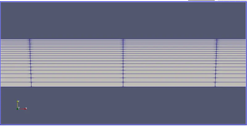
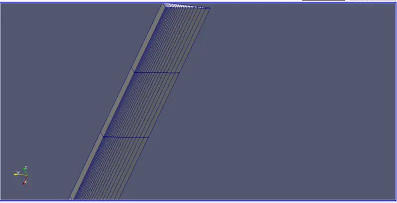
MESH:
FOR 10:
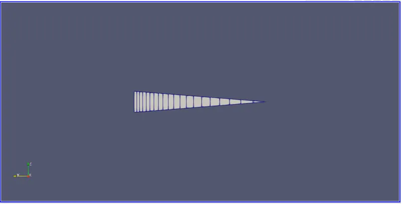
FOR 25:
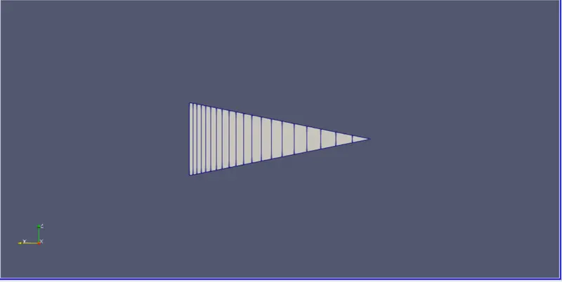
FOR 45:
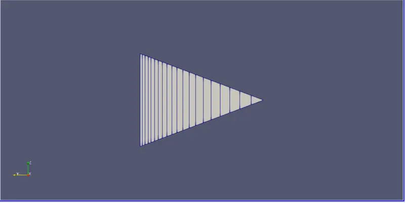
MESH AT CENTER:
VELOCITY PROFILE VARIATION AT A DISTANCE X FROM INLET:
FOR 10:
x = 2
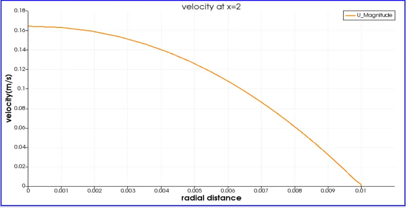
the velocity profile shows the velocity is 0.164 at x = 2 from entrance and the flow is fully developed.
VELOCITY PROFILE FOR HAGEN-POISEUILLE FLOW:
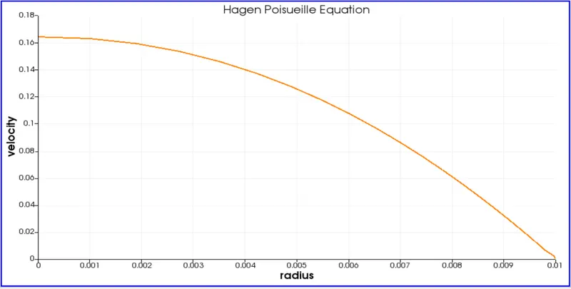
The velocity is maximum at centre and almost zero near the walls.
The velocity flow of a hagen poiseuelli flow exactly matches with velocity profile when x = 2m from the entrance and the profile doesn't changes after that as the flow is fully developed.
PRESSURE PROFILE:
FOR 10:
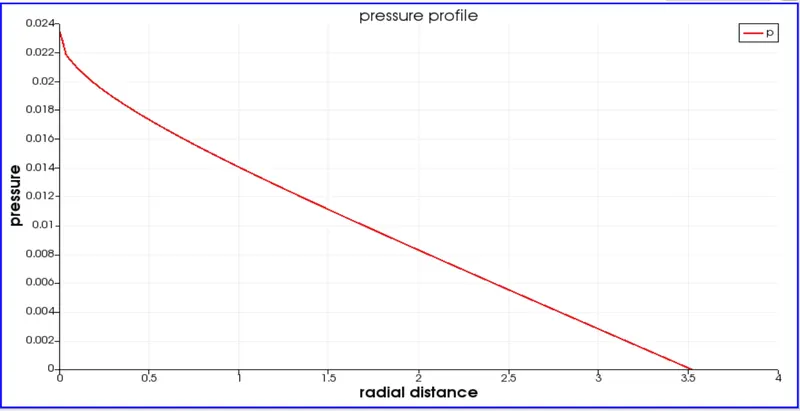
The pressure keep on reduces from center and almost zero near the walls .
SHEAR STRESS VARIATION WITH RADIUS:
FOR 10
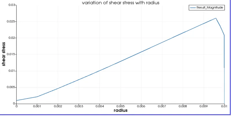
The plot shows that the shear stress is closer to zero at center and increases and maximum near walls.
|
CONDITION |
MAX.VELOCITY |
PRESSURE DROP |
SHEAR STRESS |
|
10(WEDGE) |
0.1648 |
0.0238 |
0.0262 |
|
25(WEDGE) |
0.1648 |
0.0238 |
0.0262 |
|
45(WEDGE) |
0.1648 |
0.0238 |
0.0261 |
CONCLUSION:
- Velocity profile is fully developed at hydrodynamic entrance length.
- velocity is almost constant in all angles.
- Pressure is maximum at inlet and tends to gauge pressure at outlet.
- Shear stress is zero at centre and maximum at near walls.
- Numerical data is valid with exact solution with negligible deviation.
CASE 2: SYMMETRY BC:
MATLAB CODE:
MATLAB CODE TO GENERATE BLOCKMESHDICT FILE:
clear all
close all
clc

%reynolds number
re = 2100;

%total length
l = input('length of the pipe : ');

%density
rho = 996;

%viscosity
mu = 0.799e-3;

%diameter
D = input('diameter of pipe : ');

%radius
r = D/2;

%entrance length
l_e = 0.06*D*re;

%angle
theta = input('wedge angle : ');

%simple grading
nx = 200;
ny = 20;
nz = 1;

%average velocity
v_avg = (re*mu)/(rho*D);

%maximum velocity
v_max = 2*v_avg;

%pressure drop
delta_p = (32*mu*l*v_avg)/(D^2);

%kinematic pressure drop
kin_p = (delta_p)/rho;

%creating blockmeshdict file
h1 = '/*-------------------------------*- c++ -*-------------------------------------*\';
h2 = '   =========                  |                                                  ';
h3 = '   \\      /   F ield         |  OpenFOAM: The Open Source CFD Toolbox           ';
h4 = '    \\    /    O peration     |  Website:  https://openfoam.org                  ';
h5 = '     \\  /     A nd           |  Version:  8                                     ';
h6 = '      \\/      M anipulation  |                                                  ';
h7 = '\*-----------------------------------------------------------------------------*/';
h8 = 'FoamFile';
h15 = '//*****************************************************************************//';

%opening the file
f1 = fopen('blockMeshDict.txt','w');

%writing comments
fprintf(f1,'%s\n',h1);
fprintf(f1,'%s\n',h2);
fprintf(f1,'%s\n',h3);
fprintf(f1,'%s\n',h4);
fprintf(f1,'%s\n',h5);
fprintf(f1,'%s\n',h6);
fprintf(f1,'%s\n',h7);

fprintf(f1,'%s\n',h8);
fprintf(f1,'{\n');
fprintf(f1,'%10s\t 2.0;\n','version');
fprintf(f1,'%9s\t ascii;\n','format');
fprintf(f1,'%8s\t dictionary;\n','class');
fprintf(f1,'%9s\t blockMeshDict;\n','object');
fprintf(f1,'}\n');
fprintf(f1,'%s\n\n',h15);

%creating conversion
fprintf(f1,'convertToMeters  1;\n\n');

%creating vertices
fprintf(f1,'vertices\n');
fprintf(f1,'(\n');
fprintf(f1,'\t (%d %d %d)\n',0,0,0);
fprintf(f1,'\t (%d %d %d)\n',0,r*cosd(theta/2),r*sind(theta/2));
fprintf(f1,'\t (%d %d %d)\n',0,r*cosd(theta/2),-r*sind(theta/2));
fprintf(f1,'\t (%d %d %d)\n',l,0,0);
fprintf(f1,'\t (%d %d %d)\n',l,r*cosd(theta/2),r*sind(theta/2));
fprintf(f1,'\t (%d %d %d)\n',l,r*cosd(theta/2),-r*sind(theta/2));
fprintf(f1,');\n\n');

%creating blocks
fprintf(f1,'blocks\n');
fprintf(f1,'(\n');
fprintf(f1,'\t hex (0 3 5 2 0 3 4 1)(%d %d %d) simpleGrading(1 0.2 1)\n',nx,ny,nz);
fprintf(f1,');\n\n');

%creating edges
fprintf(f1,'edges\n');
fprintf(f1,'(\n');
fprintf(f1,'\t arc 1 2 (%f %f %f)\n',0,r,0);
fprintf(f1,'\t arc 4 5 (%f %f %f)\n',l,r,0);
fprintf(f1,');\n\n');

%creating boundary
fprintf(f1,'boundary\n');
fprintf(f1,'(\n');

%inlet
fprintf(f1,'\t inlet\n');
fprintf(f1,'\t {\n');
fprintf(f1,'\t\t type patch;\n');
fprintf(f1,'\t\t faces\n');
fprintf(f1,'\t\t (\n');
fprintf(f1,'\t\t\t (0 1 2 0)\n');
fprintf(f1,'\t\t );\n');
fprintf(f1,'\t }\n');

%outlet
fprintf(f1,'\t outlet\n');
fprintf(f1,'\t {\n');
fprintf(f1,'\t\t type patch;\n');
fprintf(f1,'\t\t faces\n');
fprintf(f1,'\t\t (\n');
fprintf(f1,'\t\t\t (3 5 4 3)\n');
fprintf(f1,'\t\t );\n');
fprintf(f1,'\t }\n');

%top
fprintf(f1,'\t top\n');
fprintf(f1,'\t {\n');
fprintf(f1,'\t\t type wall;\n');
fprintf(f1,'\t\t faces\n');
fprintf(f1,'\t\t (\n');
fprintf(f1,'\t\t\t (1 4 5 2)\n');
fprintf(f1,'\t\t );\n');
fprintf(f1,'\t }\n');

%back
fprintf(f1,'\t back\n');
fprintf(f1,'\t {\n');
fprintf(f1,'\t\t type symmetry;\n');
fprintf(f1,'\t\t faces\n');
fprintf(f1,'\t\t (\n');
fprintf(f1,'\t\t\t (0 2 5 3)\n');
fprintf(f1,'\t\t );\n');
fprintf(f1,'\t }\n');

%front
fprintf(f1,'\t front\n');
fprintf(f1,'\t {\n');
fprintf(f1,'\t\t type symmetry;\n');
fprintf(f1,'\t\t faces\n');
fprintf(f1,'\t\t (\n');
fprintf(f1,'\t\t\t (0 3 4 1)\n');
fprintf(f1,'\t\t );\n');
fprintf(f1,'\t }\n');

%axis
fprintf(f1,'\t axis\n');
fprintf(f1,'\t {\n');
fprintf(f1,'\t\t type empty;\n');
fprintf(f1,'\t\t faces\n');
fprintf(f1,'\t\t (\n');
fprintf(f1,'\t\t\t (0 3 3 0)\n');
fprintf(f1,'\t\t );\n');
fprintf(f1,'\t }\n');
fprintf(f1,');\n\n');

%creating merge patch pairs
fprintf(f1,'mergePatchPairs\n(\n');
fprintf(f1,');\n');

fprintf(f1,'%s',h15);

%closing the file
fclose(f1)
MATLAB CODE:
- The above matlab code takes the user defined wedge angle and uses that angle to calculate the vertices for the mesh.
- The entrance length is calculated and 1m is added to the value so as to observe the fully developed flow.
- The file blockMeshDict.txt file is created and is write format.
- The block is defined and the mesh refinement is done by using simple grading.
- The edges is also defined.
- The boundary conditions are defined for inlet, outlet, top, bottom and axis.
BLOCKMESHDICT FILE FOR WEDGE ANGLE 10:
/*-------------------------------*- c++ -*-------------------------------------*\
   =========                  |
   \\      /   F ield         |  OpenFOAM: The Open Source CFD Toolbox
    \\    /    O peration     |  Website:  https://openfoam.org
     \\  /     A nd           |  Version:  8
      \\/      M anipulation  |
\*-----------------------------------------------------------------------------*/
FoamFile
{
   version	 2.0;
   format	 ascii;
   class	 dictionary;
   object	 blockMeshDict;
}
//*****************************************************************************//

convertToMeters  1;

vertices
(
	 (0 0 0)
	 (0 9.961947e-03 8.715574e-04)
	 (0 9.961947e-03 -8.715574e-04)
	 (3.520000e+00 0 0)
	 (3.520000e+00 9.961947e-03 8.715574e-04)
	 (3.520000e+00 9.961947e-03 -8.715574e-04)
);

blocks
(
	 hex (0 3 5 2 0 3 4 1)(200 20 1) simpleGrading(1 0.2 1)
);

edges
(
	 arc 1 2 (0.000000 0.010000 0.000000)
	 arc 4 5 (3.520000 0.010000 0.000000)
);

boundary
(
	 inlet
	 {
		 type patch;
		 faces
		 (
			 (0 1 2 0)
		 );
	 }
	 outlet
	 {
		 type patch;
		 faces
		 (
			 (3 5 4 3)
		 );
	 }
	 top
	 {
		 type wall;
		 faces
		 (
			 (1 4 5 2)
		 );
	 }
	 back
	 {
		 type symmetry;
		 faces
		 (
			 (0 2 5 3)
		 );
	 }
	 front
	 {
		 type symmetry;
		 faces
		 (
			 (0 3 4 1)
		 );
	 }
	 axis
	 {
		 type empty;
		 faces
		 (
			 (0 3 3 0)
		 );
	 }
);

mergePatchPairs
(
);
//*****************************************************************************//
here the geometry is created and the mesh refinement is done using grading factor.
CONTROLDICT FILE:
/*--------------------------------*- C++ -*----------------------------------*\
  =========                 |
  \\      /  F ield         | OpenFOAM: The Open Source CFD Toolbox
   \\    /   O peration     | Website:  https://openfoam.org
    \\  /    A nd           | Version:  8
     \\/     M anipulation  |
\*---------------------------------------------------------------------------*/
FoamFile
{
    version     2.0;
    format      ascii;
    class       dictionary;
    location    "system";
    object      controlDict;
}
// * * * * * * * * * * * * * * * * * * * * * * * * * * * * * * * * * * * * * //

application     icoFoam;

startFrom       startTime;

startTime       0;

stopAt          endTime;

endTime         50;

deltaT          0.01;

writeControl    timeStep;

writeInterval   20;

purgeWrite      0;

writeFormat     ascii;

writePrecision  6;

writeCompression off;

timeFormat      general;

timePrecision   6;

runTimeModifiable true;
// ************************************************************************* //
The type of solver and the start and end time of simulation is defined in this file.
TRANSPORT PROPERTIES:
/*--------------------------------*- C++ -*----------------------------------*\
  =========                 |
  \\      /  F ield         | OpenFOAM: The Open Source CFD Toolbox
   \\    /   O peration     | Website:  https://openfoam.org
    \\  /    A nd           | Version:  8
     \\/     M anipulation  |
\*---------------------------------------------------------------------------*/
FoamFile
{
    version     2.0;
    format      ascii;
    class       dictionary;
    location    "constant";
    object      transportProperties;
}
// * * * * * * * * * * * * * * * * * * * * * * * * * * * * * * * * * * * * * //

nu              [0 2 -1 0 0 0 0] 8.02e-7;


// ************************************************************************* //
kinematic viscosity of water at 30 celcius is 8.02e-7
INITIAL CONDITIONS:
PRESSURE:
/*--------------------------------*- C++ -*----------------------------------*\
  =========                 |
  \\      /  F ield         | OpenFOAM: The Open Source CFD Toolbox
   \\    /   O peration     | Website:  https://openfoam.org
    \\  /    A nd           | Version:  8
     \\/     M anipulation  |
\*---------------------------------------------------------------------------*/
FoamFile
{
    version     2.0;
    format      ascii;
    class       volScalarField;
    object      p;
}
// * * * * * * * * * * * * * * * * * * * * * * * * * * * * * * * * * * * * * //

dimensions      [0 2 -2 0 0 0 0];

internalField   uniform 0;

boundaryField
{
    inlet
    {
        type            zeroGradient;
    }

    outlet
    {
        type            fixedValue;
        value           uniform 0;
    }

    topwall
    {
        type            zeroGradient;
    }

    back
    {
        type            symmetry;
    }

    front
    {
        type            symmetry;
    }

    axis
    {
        type            empty;
    }
}

// ************************************************************************* //
In this file we are fixing the outlet initial conditions as a fixed value because we assume pressure at the pipe outlet to be normal air pressure which is measured as 0.
VELOCITY:
/*--------------------------------*- C++ -*----------------------------------*\
  =========                 |
  \\      /  F ield         | OpenFOAM: The Open Source CFD Toolbox
   \\    /   O peration     | Website:  https://openfoam.org
    \\  /    A nd           | Version:  8
     \\/     M anipulation  |
\*---------------------------------------------------------------------------*/
FoamFile
{
    version     2.0;
    format      ascii;
    class       volVectorField;
    object      U;
}
// * * * * * * * * * * * * * * * * * * * * * * * * * * * * * * * * * * * * * //

dimensions      [0 1 -1 0 0 0 0];

internalField   uniform (0 0 0);

boundaryField
{
    inlet
    {
        type            fixedValue;
        value           uniform (0.084 0 0);
    }

    outlet
    {
        type            zeroGradient;
    }

    topwall
    {
        type            noSlip;
    }

    back
    {
        type            symmetry;
    }

    front
    {
        type            symmetry;
    }

    axis
    {
        type            empty;
    }
}

// ************************************************************************* //
In this file we are define the inlet initial conditions as a average velocity value that we calculated previously.
RESULT:
MESH:
FOR 10:
FOR 25:
FOR 45:
MESH AT CENTER:
VELOCITY PROFILE VARIATION AT A DISTANCE X FROM INLET:
FOR 10:
x = 2
FOR 25:
FOR 45:
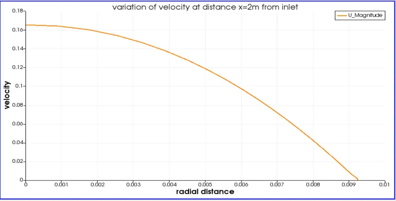
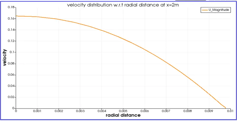
the velocity profile shows the velocity is 0.164 at x = 2 from entrance and the flow is fully developed.
VELOCITY PROFILE FOR HAGEN-POISEUILLE FLOW:
The velocity is maximum at centre and almost zero near the walls.
The velocity flow of a hagen poiseuelli flow exactly matches with velocity profile when x = 2m from the entrance and the profile doesn't changes after that as the flow is fully developed.
PRESSURE PROFILE:
FOR 10:
FOR 25:
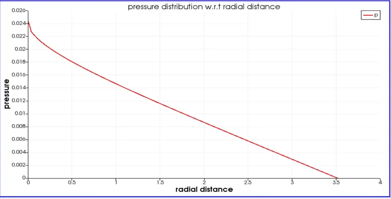
FOR 45:
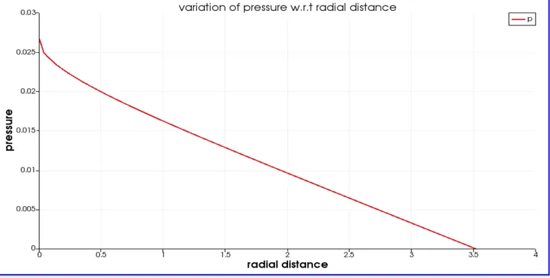
The pressure keep on reduces from center and almost zero near the walls .
SHEAR STRESS VARIATION WITH RADIUS:
FOR 10
FOR 25
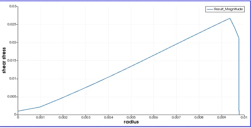
FOR 45
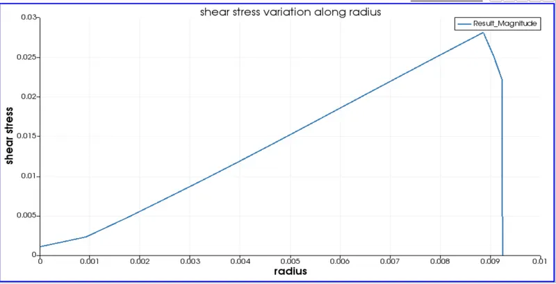
The plot shows that the shear stress is closer to zero at center and increases and maximum near walls.
|
CONDITION |
MAX.VELOCITY |
PRESSURE DROP |
SHEAR STRESS |
|
10(SYMMETRY) |
0.1643 |
0.0238 |
0.0280 |
|
25(SYMMETRY) |
0.1643 |
0.0240 |
0.0274 |
|
45(SYMMETRY) |
0.1643 |
0.0266 |
0.0280 |
CONCLUSION:
- Velocity profile is fully developed at hydrodynamic entrance length.
- velocity is almost constant in all angles.
- Pressure is maximum at inlet and tends to gauge pressure at outlet.
- Shear stress is zero at centre and maximum at near walls.
- Numerical data is valid with exact solution with negligible deviation.
OVERALL CONCLUSION:
- Parabolic profile is maintained in all wedge angles.
- Symmetry boundary conditions gives more accurate results than wedge boundary conditions.
- Symmetry boundary conditions take more execution time than wedge boundary conditions.
- The velocity profiles are same in both boundary and symmetry conditions.