Week 12: Shell and Tube Heat Exchanger simulation
Aim - Shell and Tube Heat Exchanger simulation. Water in shell side and Oil in tube side.
Introduction / Working -
Heat exchangers are one of the most used equipment in the process industries. Heat exchangers are used to transferring heat between two process streams. The heat exchanger is required in a process involving cooling, heating, condensation, boiling, or evaporation.
Shell and tube heat exchangers consist of a series of tubes. One set of these tubes contains the fluid that must be either heated or cooled. The second fluid runs over the tubes that are being heated or cooled so that it can either provide the heat or absorb the heat required. A set of tubes is called tube bundle and can be made up of several types of tubes: plain, longitudinally finned, etc. Shell and tube heat exchangers are typically used for high-pressure applications. This is because the shell and tube heat exchangers are robust due to their shape. Heat exchangers are widely used in industry both for cooling and heating large-scale industrial processes. The type and size of the heat exchanger used can be made to suit a process depending on the type of fluid, its phase, temperature, density, viscosity, pressure, chemical composition, and various other thermodynamic properties.
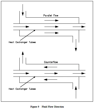
Parallel-flow vs Counter-flow heat exchanger
- In the parallel-flow arrangement, the hot and cold fluids enter at the same end, flow in the same direction, and leave at the same end.
- In the counter-flow arrangement, the fluids enter at opposite ends, flow in opposite directions, and leave at opposite ends.
- In Parallel flow, the temperature of the cold fluid exiting the heat exchanger never exceeds the lowest temperature of the hot fluid. Also, the temperature difference is large as compared to counter flow HE. Hence Counter-flow is better.
Geometry -
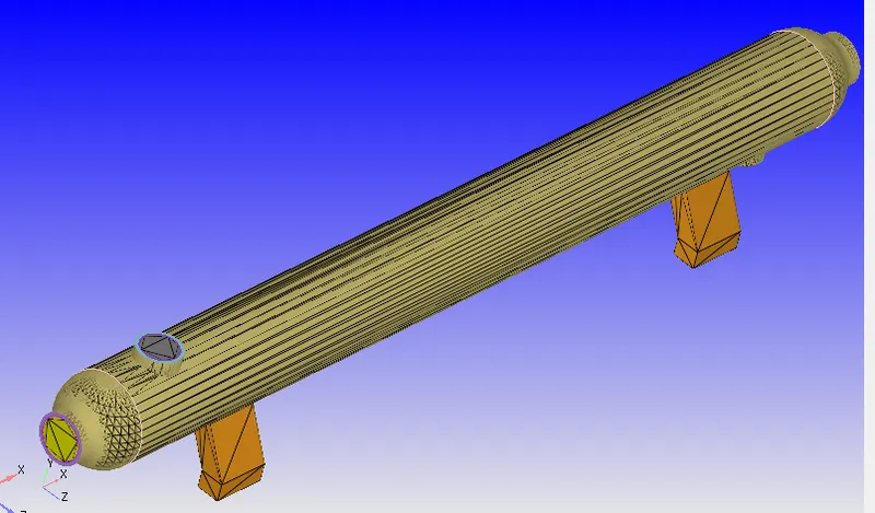
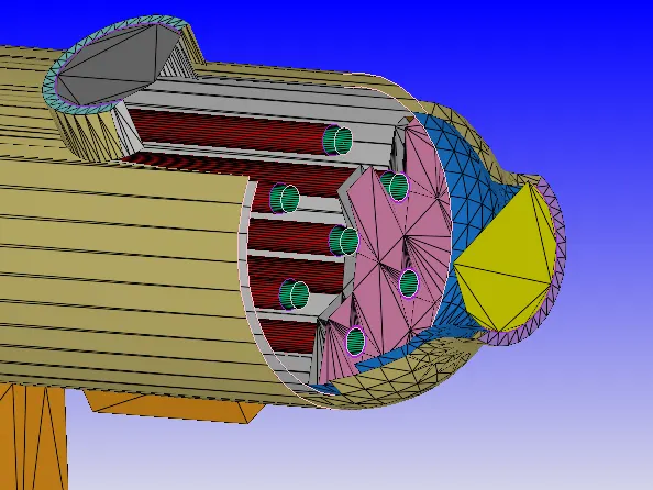
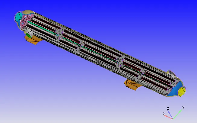
Drag and drop the geometry and clean all the open edges triangles & intersection errors, create inlet & outlet boundary, delete additional surfaces of the tubes, etc.
Case setup -
- Application type › Time-based
- Materials>
- Liquid Sim - H2O, C2H6O2
- Solid Sim - COPPER
- Species - H2O, C2H6O2, COPPER
- Simulation parameters
- Run Parameters - Transient
- Simulation time parameters - 1.5s
- Solver parameters - Density-based NS solver
- Boundary conditions/parameters are assigned as follows -
- Initial Conditions and Events
-
Physical Models - RNG K-E and Super cycling
-
Grid Control - dx=dy=dz=0.01 m with Temperature AMR
-
Output/Post-processing o Time interval 3D O/p files - 0.015s
-
Advanced Parameters
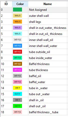
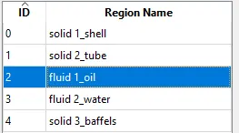
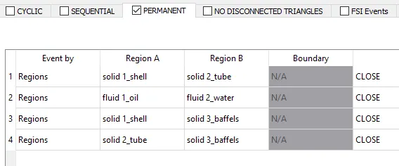
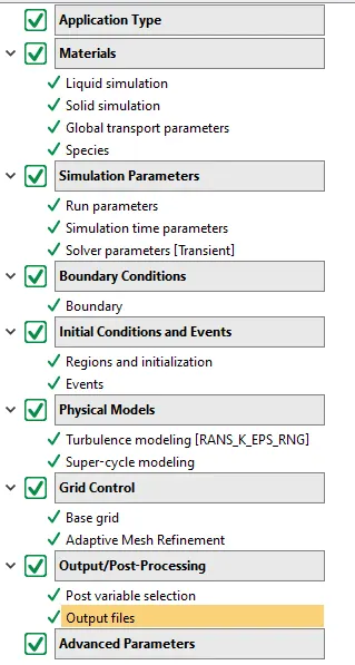
Observations -
- Counter Flow setup -
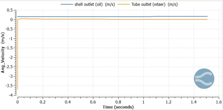
- Velocity -
-
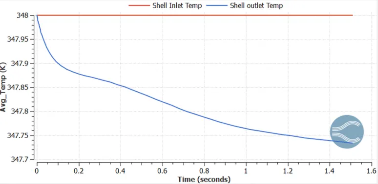
Temperature- Parallel Flow
- Shell side - Oil
- Tube side - water
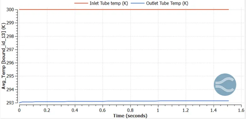
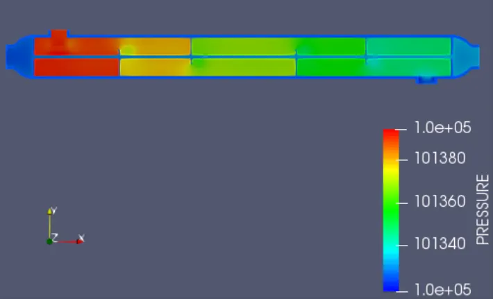
- Pressure -
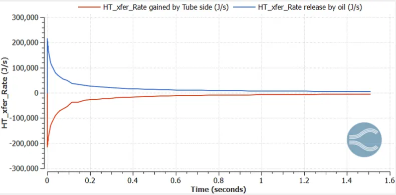
- Heat transfer rate -
- Parallel Flow setup -
- Velocity -
-
Temperature- Parallel Flow
- Shell side - Oil
- Tube side - water
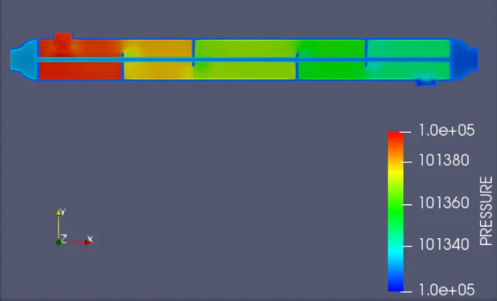
- Pressure -
- Heat transfer rate -
- Calculations
-
Parameter Unit Counter flow Parallel Flow Temperature of cold fluid at inlet T_ci ° C 20 20 Temperature of hot fluid at inlet T_hi ° C 75 75 Outer Diameter of Tube d_o mm 23 23 Inner Diameter of Tube d_i mm 20 20 h_i h_i W/(m^2-K) 4500 4500 h_o h_o W/(m^2-K) 1250 1250 Length of tubes l M 2.4 2.4 Cp(H2O) Cp(H2O) J/(kg-K) 4200 4200 Cp(C2H602) Cp(C2H602) J/(kg-K) 2600 2600 Number of tubes n nos 7 7 Mass flow rate of cold fluid m_c kg/s 1.162 1.162 Mass flow rate of hold fluid m_h kg/s 1.252 1.252 Temperature of cold fluid at inlet T_co ° C 25.3 25.3 Temperature of hot fluid at inlet T_ho ° C 65.8 65.8 Temp difference at inlet side DTi ° C 45.8 55 Temp difference at outlet side DTo ° C 49.7 40.5 DTi - DTo 3.9 14.5 DTi / DTo 0.92 1.36 ln (DTi / DTo) 0.08 0.31 LMTD
(DTi - DTo) / ln (DTi / DTo)° C 47.72 47.38 Dia ratio do/di 1.15 1.15 heat transfer co-efficient tube (do/di) / hi 0.0003 0.0003 heat transfer co-efficient oil 1 / ho 0.0008 0.0008 Total heat transfer co-efficient 1 / U (m^2-K)/W 0.0011 0.0011 Overall heat transfer co-efficient U W/(m^2-K) 947 947 Tube surface area At m2 0.023 0.023 Heat Transfer Rate - oil Q = U*At*LMTD KW 1022 1015 v = m*density*areaVelocity of fluid water v_c m/s 29.2 29.2 Velocity of fluid oil v_h m/s 31.4 31.4
-
-
Drawbacks of shell and tube heat exchanger:
-
Heat exchanger effectiveness is less.
-
Cleaning and maintenance is troublesome since a tube cooler requires enough clearance at one end to remove the tube nest.
-
The capacity of the tube cooler cannot be increased.
-
Requires more space in comparison to plate coolers
-
-
Fouling factors
-
We know the surface of the heat exchangers does not remain clean after it has been in use for some time. The surface becomes fouled with scaling or deposits. The effects of these deposits affect the value of the overall heat transfer co-efficient. This effect is taken care of by introducing an additional thermal resistance called fouling resistance.
-
- Conclusion
- The required Simulation of Shell and Tube HE is done and calculations using the results are done as well.