Week 12:Project 2-Meshing of Rear Wheel Holder challenge
AIM; To generate mesh for the given floor component in hypermesh.
MAIN OBJECTIVE;
- Import model from its respective location. The model may be the step/IGS /hm file.
- Perform the topology clean upon the geometry, Identify and remove all possible errors in the geometry.
- After visualizing the model, we get the idea about which category the model will fall into. Like sheet metal/plastic/casting part. So, we can choose the meshing option accordingly.
- Extract Mid-surface to the floor panel by taking an auto mid surface to the component.
- Again, perform the cleanup operation on the Mid surface if needed.
- Remove the buttons which are shown below, because it will lead to failing the elements.
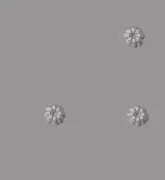
- fill the surfaces and after deleting the buttons on the surface.
- Now generate mesh on the extracted mid-surface as per the given Quality criteria.
- Check for any Quality failure and remove them.
FLOOR PANEL:
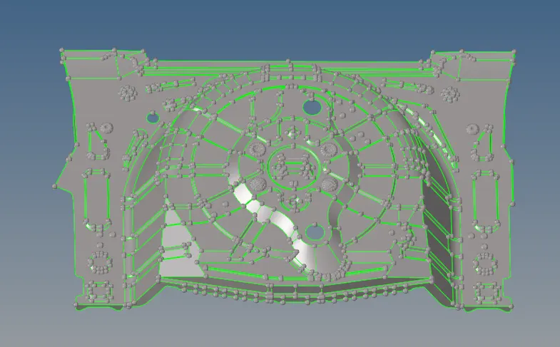
given quality criteria.
Target Element Length = 5 Units
| S.N | Quality Criteria | Value |
| 1 | Aspect Ratio | 5 |
| 2 | Skewness | 45 |
| 3 | Warping | 15 |
| 4 | Taper | 0.5 |
| 5 | Min. Length | 2 Units |
| 6 | Max. Length | 8 Units |
| 7 | Min angle Quad | 45 |
| 8 | Max angle Quad | 135 |
| 9 | Min angle Tria | 20 |
| 10 | Max angle Tria | 120 |
| 10 | Tria % | 10 |
PROCEDURE;
- After importing the model, first we have to check for solids in the Geometry and delete it. After that performed Topology. The topology just eliminates the un-necessary geometrical distortion (geometrical irregularities/ missing surfaces/ Intersecting surfaces etc.) in the model. This distortion is mainly due to the fact that the models are getting imported from different CAD design software. You can find this option to clean up the geometry in the geometry panel open>quick edit tools > by using the tools we have to eliminate the errors which are present in the component part.
2. put the model in a wireframe mode where we see the lines clearly and it shows any defects which are present in the part. The green lines indicate the connecting surfaces. In the imported model, all the geometry should have represented by green lines.
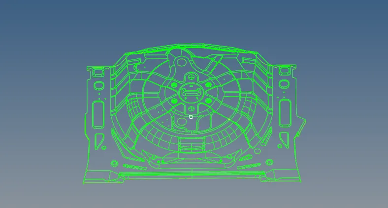
3.The yellow lines indicate the triple connections mean more than two lines are in contact with each other. For the plastic components, it is ok to have triple connections as it contains rib likes structures but in the sheet metal part, it is not acceptable as they have uniform thickness throughout.
4.In the geometry panel we have options from the panel that will help to get rid of many of the geometry-related errors. There are so many options available for geometry temp nodes, lines, surface, surface edit, distance, Defeature, mid surface, quick edit panel, etc. which would help us for initial cleanup.
Lines:

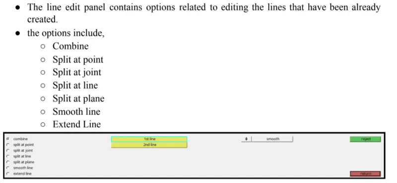
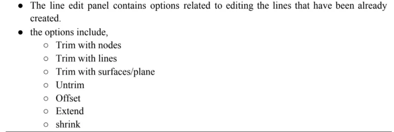
Line edit:
Surfaces:

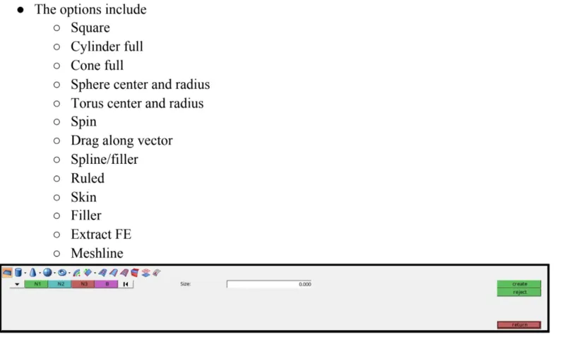
Surface edit:

Distance:

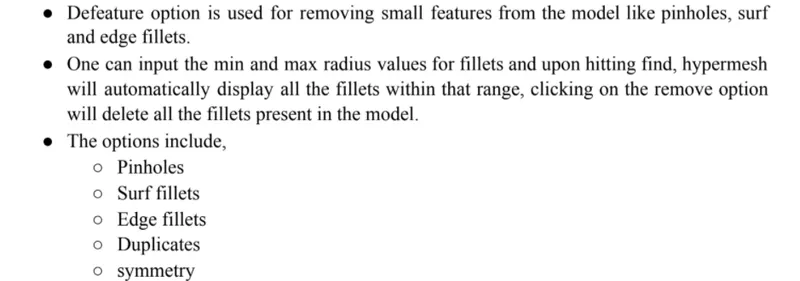
Defeature:

Midsurface:

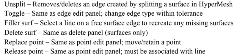
Quick edit tools:

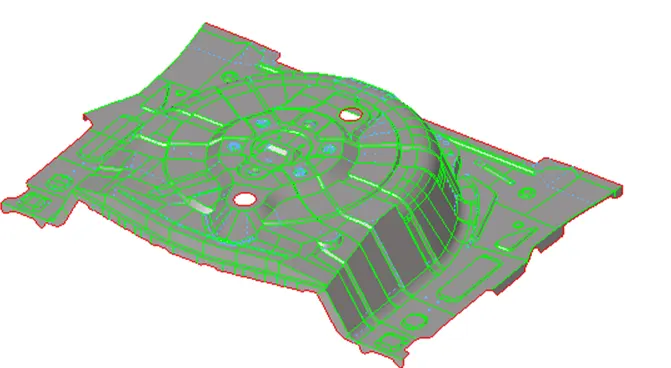
MID SURFACE EXTRACTIONS;
There are two methods for MID surface extraction one is Auto mid surface extraction using a mid surface panel from the geometry panel and another one is a manual one by using the offset option. For more complex geometry we go with the Manual method to capture detailed features over the model body because they have a different thickness which used to perform the auto mid is too hard and it will lead to destroying the surfaces and all other body components. We took auto mid when we have a uniform thickness among the body.
Manual MID surface ;
GO to the surface edit panel> offset >Select the surfaces > duplicate the surfaces>current component>set the offset value>offset the body by giving an vector normal.

- Under this method, we have to select the surface part by part and make an offset of it.
- As you can see in the panel screenshot above there is an option for surface selection than with how much distance you want to do offset. The main thing here to notice is we are just offsetting the outer surface of the geometry by some defined value so make "Duplicate" of it is the important thing. Also, the vector direction is important for that we have an option named "vector normal and reverse normal" to identify and reverse the vector if it's not in the desire offsetting direction.
Automatic MID surface ;
GO to the geo>midsurface>take auto mid surf before that we have to select the extraction options and
choose among one of them >select the surface and create mid surface among the component.
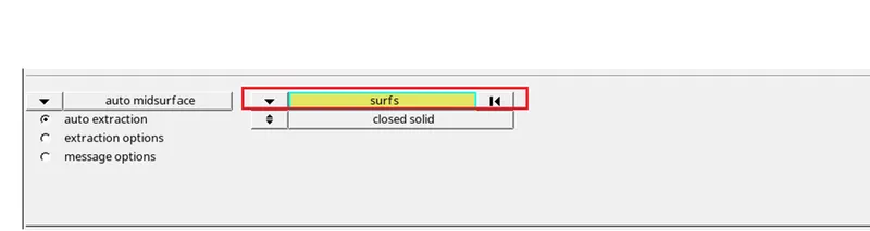
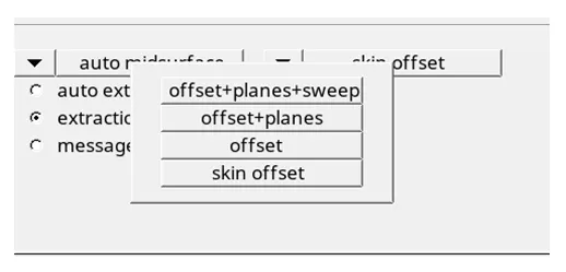
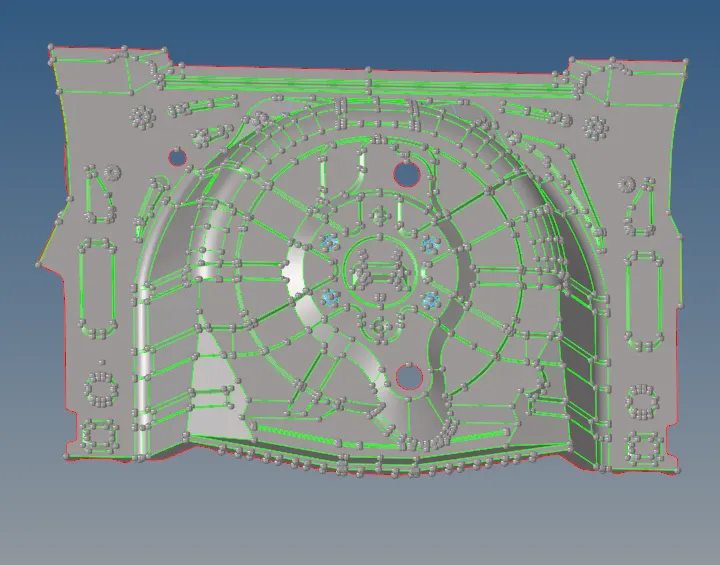
2D Automesh;
There are separate Panels and sub-panels available in the Hypermesh to deploy different sorts of mesh-like 1D, 2D, 3D. For this project, as we are working on the Sheet-metal component we don't need 3D meshing. Usually, sheet metal components or components having a thickness less than 6mm falls under the 2D meshing.

you can set the target length and the type of mesh. Make sure you have selected the surface. After hitting the mesh button, the mesh will automatically get generated on the mid surface.
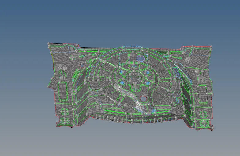
After generating the mesh on the mid surface we edit the mesh by clean up tools options which are present in the quality index panel.

smooth: used to smooth the elements which are the uneven flow of the mesh.
swap edge; used to swap the tria elements which are present in the edges of the component.
drag tri elements; used to drag the tria elements which is not preferred in the mesh.
element optimize; used to optimize the mesh elements in order to get in a smoother one.
combine trias; used to the combine the two tria elements which are in the side by side manner.
Edit element;
create; used to create the quads or trias elements in the mesh region.
combine; used to combine the quad elements.
split; used to split the elements according to the particular usage.

In order to check the quality of mesh we go to tool > check elements >2d.

Error;
Some elements are failing for multiple Quality issues but they are unavoidable I had preferred the Geometry and feature capturing over Quality in those regions.
CHECK EDGES;
Go to tools >edges>select elements> find edges.
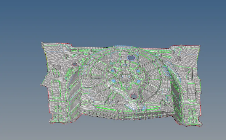
use preview equivalence in order to check the connectivity of the elements and equivalence the elements.

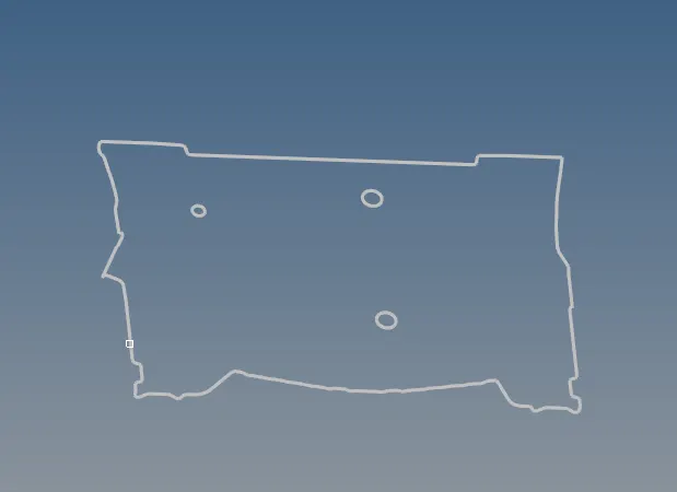
Here we can see clearly the edges of the outer body component in the below figure.
CONCLUSION;
We generate the mesh on the given component by following the quality criteria which was assigned for the mesh elements.
learned about the topology clean-up and mud surfaces and finally generate the mesh for the given component.