Week 12:Project 2-Meshing of Rear Wheel Holder challenge
Objective-
Follow the below-mentioned quality criteria, mesh the component given below and assign thickness:
Target Element Length = 5 Units
| S.N | Quality Criteria | Value |
| 1 | Aspect Ratio | 5 |
| 2 | Skewness | 45 |
| 3 | Warping | 15 |
| 4 | Taper | 0.5 |
| 5 | Min. Length | 2 Units |
| 6 | Max. Length | 8 Units |
| 7 | Min angle Quad | 45 |
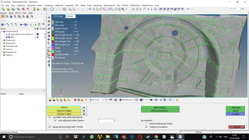
| 8 | Max angle Quad | 135 |
| 9 | Min angle Tria | 20 |
| 10 | Max angle Tria | 120 |
| 10 | Tria % | 10 |
Procedure-
1.Import the given model in Hypermesh.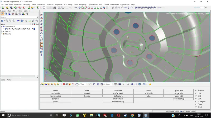
2.As we can observe, there are a lot of geometrical distortions are present.Instead of working on the parent geometry, we can extract the midsurface first and then we will proceed to work on the midsurface.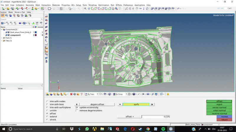
3.Because of some open surfaces due to geometrical distortions, the whole geometry here is not closed surface geometry, so while taking the midsurface we need to select the option called Incomplete solid under the surfaces section of the offset menu for taking automatic midsurface.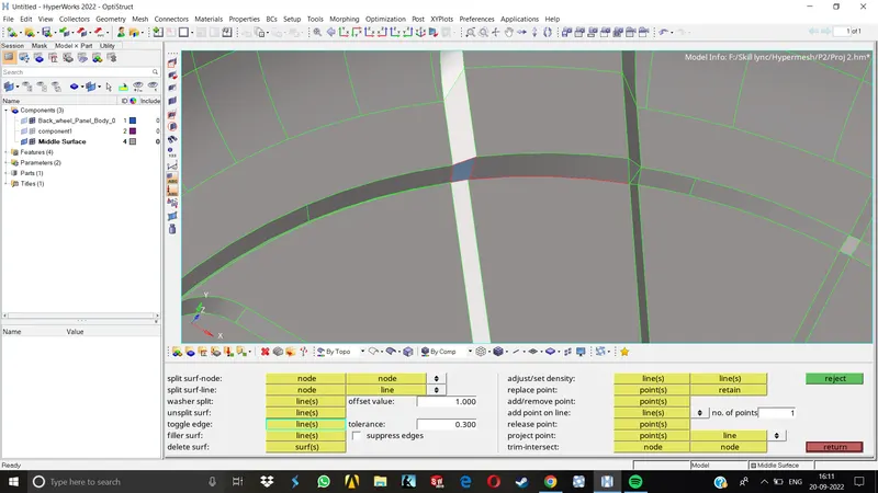
4.Once the midsurface is generated, we can now work on the distorted surfaces one by one.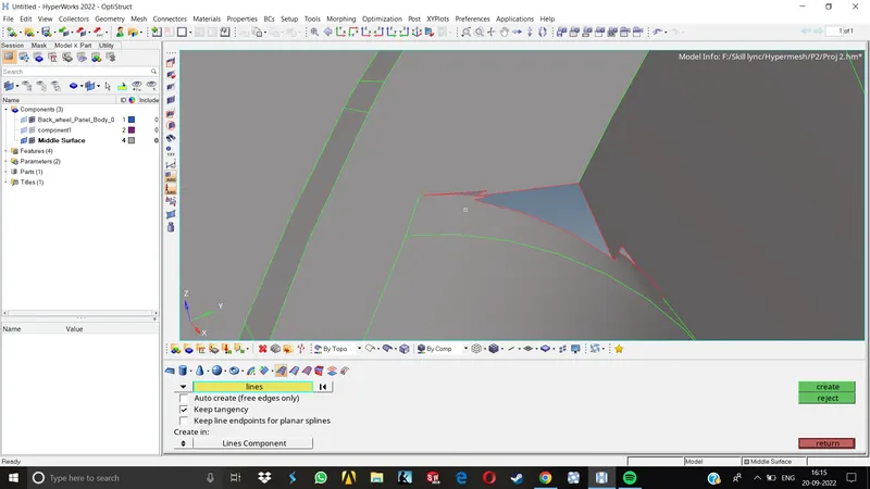
5.In some areas, some surfaces were missing.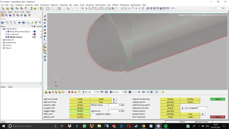
6.In other areas, the surfaces were not stitched, free edges were present. So to take care of these free edges we replaced some points, toggled some edges, made some splits in partcular areas and joioned the free edges.
7.After doing all this, the midsurface is now ready for meshing.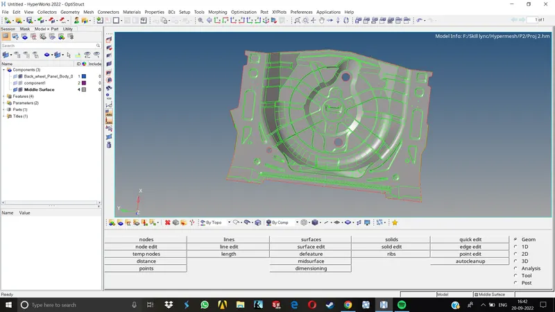
8.For maintaining a proper mesh flow, we need to split the given geometry accordingly.We also need to toggle some of the edges which may result in element failures.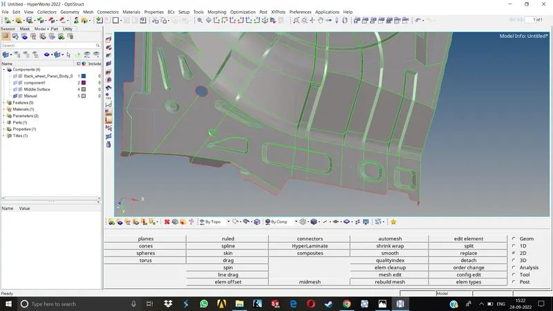
9.After splitting, we can proceed for meshing. Here the approach taken to mesh the model is from the centre of thew geometry to the outward surfaces. This way the mesh flow is easy to keep uniform.
10.Starting from the centre, the surfaces are meshed according to the specified quality criteria.
11.The mesh is then improved using various tools like Remeshing the surface, adjusting the no of nodes, Replacing some nodes, dragging some elements etc.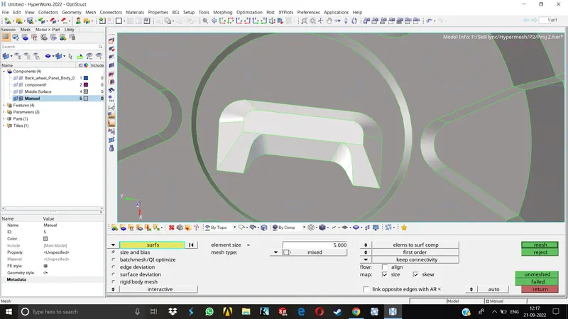
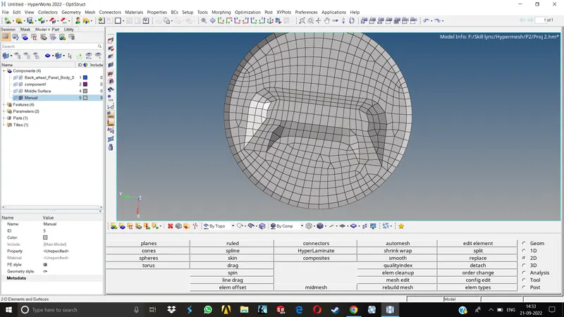
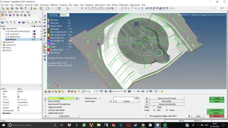
12. Now we have to deal with the failed elements for quality. We performed element cleanup as a first step , if the failure insists agian, we may have to deal with it manually by replacing some nodes, Element optimization, smoothing, remeshing, rebuliding, etc.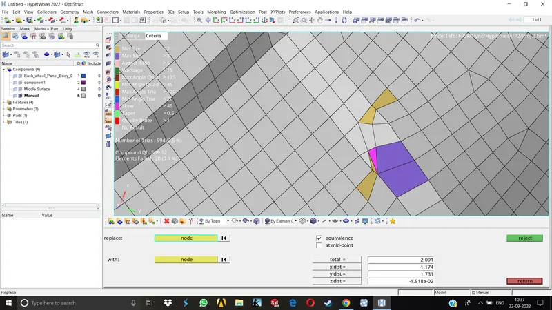
13. Once meshing is done, we can assign the material and property for the component. As this is a uniform thickness sheetmetal component, we will assign them accordingly.
14. Now we may reorder the components and properties & the model will be ready to export.
Results-
In this project, all the operations we performed were pretty similar to the earlier exercises. The main goal here was to get a good mesh flow with no failing elements and low tria concentration. Meshing this component in particular was a bit tricky as it had a lot of small features and complicated areas.
Here, we can conclude that we have successfully meshed the given component with the given quality criterias.
Final model Images-