Week 12:Project 2-Meshing of Rear Wheel Holder challenge
AIM:- To study the Meshing of Rear Wheel Holder with the help of HYPERMESH.
SOLVER:- Optistruct
OBJECTIVES:-
1 To eliminate all the geometrical errors.
2. Create the mid surface of the given component manually.
3. Generate the mesh within the given quality criteria.
1. IMPORTING COMPONENT TO HYPERMESH.
To work on the particular component we need to import that given component to hypermesh to import that we need to click on the file button and from that, we will import button and the browsing window will open and we can select our desired file and hit on import button hypermesh load all the data and file to hypermesh.
our component is the .iges format to import this format we will move to import geometry and we will select .iges as our file type and hit on import button
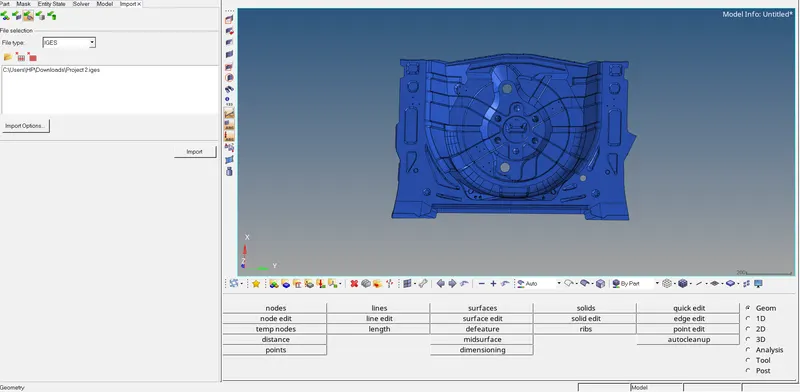
FILE>IMPORT>GEOMETRY>FILE TYPE(as our file type is .iges)>BROWSING(where our file is located)>IMPORT
2. DELETING SOLIDS
as we are doing surface meshing we need to delete solids from a current component but here no solids are present we can move to the next process.
3. ELIMINATING GEOMETRICAL ERRORS
our current component contains so many missing surfaces and geometry corrections that we can refer to the given additional files. and it also contains some missing surfaces that we can create and also some surfaces that may create failure of elements so we will try to remove them with a quick edit panel.
here we are not going to show all the errors we fixed but some common errors which will help you to understand.
i. Toggle tool
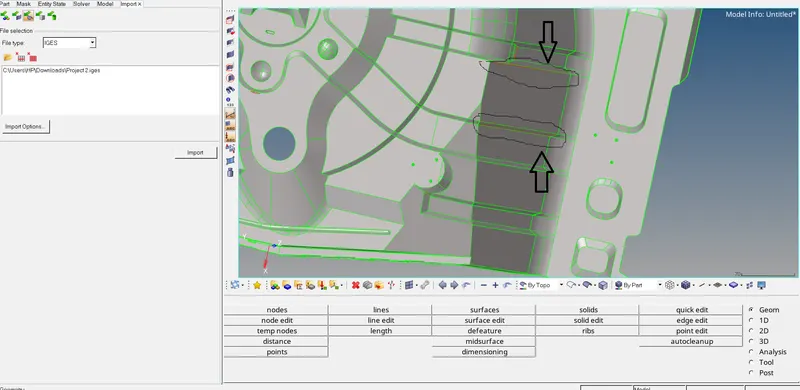
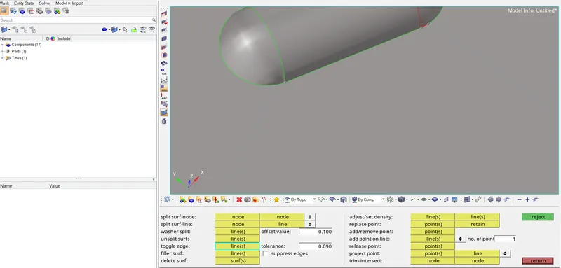
we can see some red lines in our geometry which indicate that there are some missing surfaces or that surfaces are not stuck to each other and have gaps to fix this we can simply move to the quick edit tool and try to toggle lines which we'll remove the gap between them and if that is not happening will try to increase tolerance so it will stitch the surface to each other and our issue will get fixed.
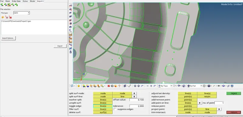
we can see after using toggle our issue got fixed the route we followed to fix this issue is
GEOMETRY>QUICK EDIT>TOGGLE edge (putting appropriate value>LINE(which we are going to toggle)
there are many other issues we are going to sort with the help of the toggle tool,
in the below image we turn on the wireframe mode so we can detect missing surfaces easily and fix them here we also use the toggle tool
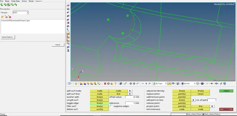
the procedure will be the same as above might tolerance value might change.
image going to come here
ii) Manifold surfaces
here we can see some yellow line which indicates might be chances of having duplicate surfaces so we try to delete the surface so we can check there for chances of having extra surfaces we used the toggle option here but in another way here we first detached the surfaces from each other by clicking on the yellow line which will convert into red line and by again clicking on it it will turn green so the additional surface will be removed.
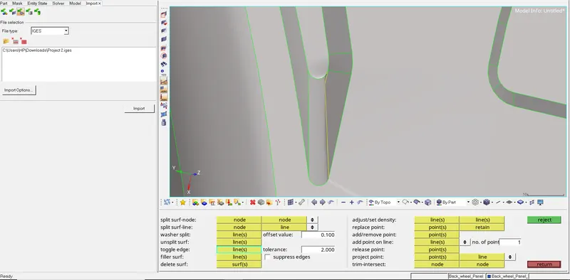
we can see the below image shows that issue got fixed.
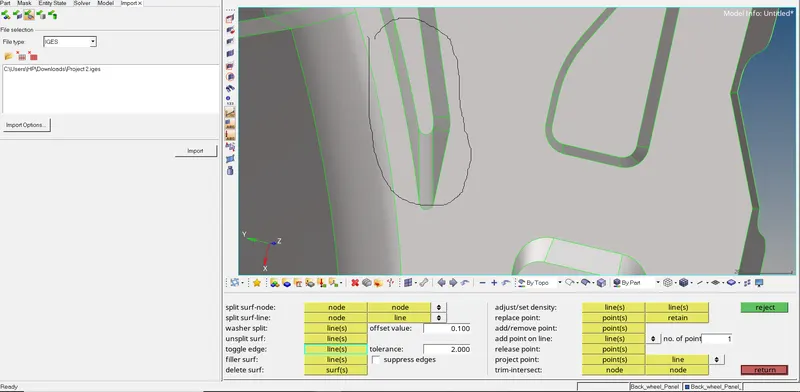
we can see the green line indicates that there are no issues.
iii) Ruled surface
here we can see the surface is missing so we need to create the surface with the help of the ruled surface we will select the lines on the missing surface were we going to create the surface and by creating a button the surface will be created and if there will be red line after creating surface because surface not stitched to each other perfectly we can use toggle option and issue will be fixed,
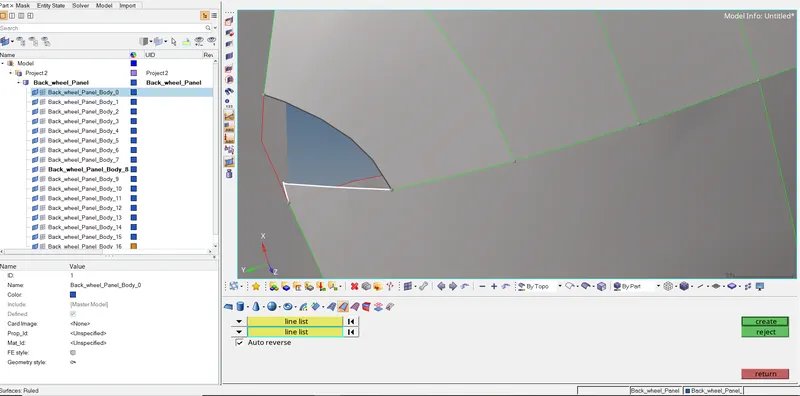
in the below image, we can see our surface got fixed,
so as we said we also used the toggle tool after creating surface
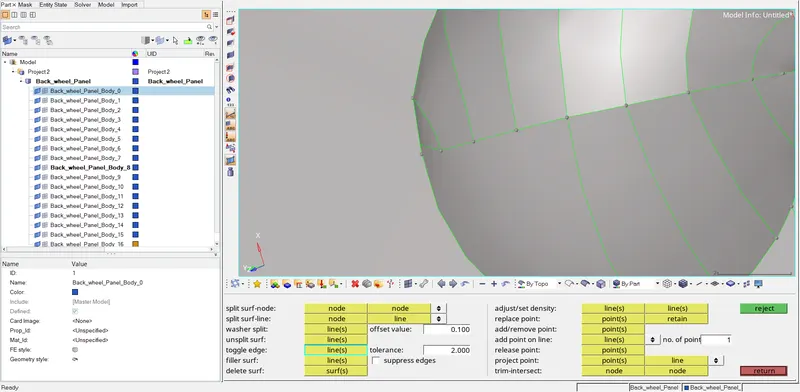
the route which we used to fix this issue,
GEOMETRY>SURFACE>RULED>LINE(of the missing surface)>CREATE
iv) Replace point
so in the below image we can see there is something issue with construction lines which distorted the surface to fix this we again using the quick edit panel but this time we are using replacing point tool here simply we will turn on all the points and we can see that replacing point will fix our issue so we select the replacing point and the point which we want to retained and by that our issue will be fixed.
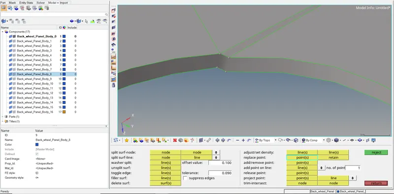
The below image shows the image after fixing the issue,
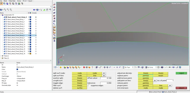
our issue got fixed,
the path we followed to fix this issue
GEOMETRY>QUICK EDIT>REPLACING POINT>POINT(which we want to replace)>RETAIN(the point where our replacing point going to move)
v) Replacing point
here also we can see there is a surface which tears out to fix there simply will use the replacing point tool and by moving the point our surface will fix
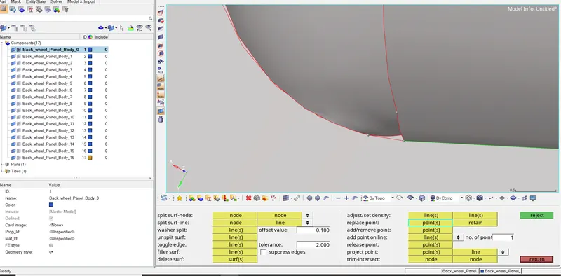
The below image shows how it will look after it got fixed,
vi) Ruled surface
here also we can see missing surfaces to fix them we again going to use the ruled surface the way which we used in the above session
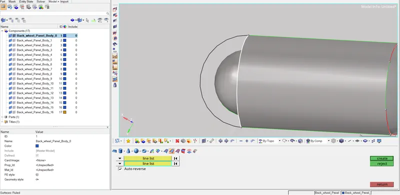
below image, after the issue got fixed,
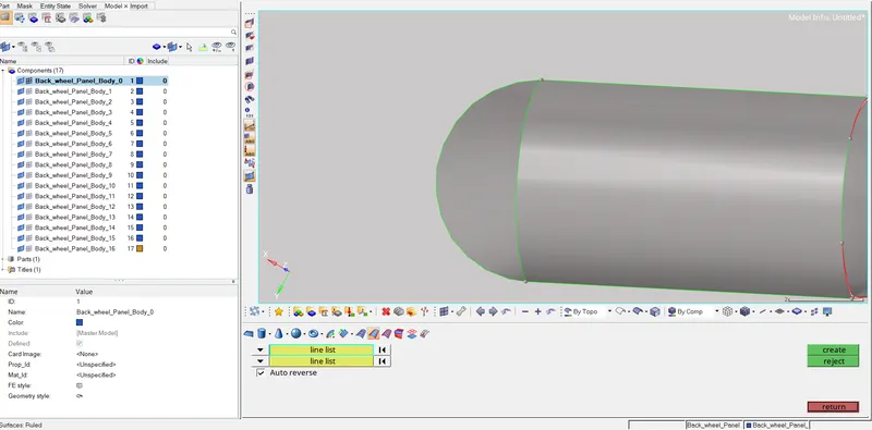
vii) Deleting extra surfaces
there are unnecessary components in a model tree that contain some additional surfaces and messing up with our parent geometry to fix that first of all, we hide our parent geometry to trace the location of those additional surfaces to cross-check if are they not a part of our parent geometry to do this we simply hide our parent geometry from the model tree
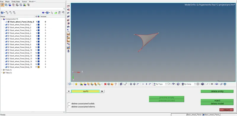
there are many like this at various places either we can delete the surface from the delete panel or we can delete all the unnecessary component which contains these unwanted surfaces,
there are many issues but those are similar to issues that we fixed and we can fix them the way we fixed above
after this, we will turn our geometry into wireframe mode to check if there is any missing surface and if have to fix them,
viii) Deleting unwanted surface
apart from these issues, there is additional information given in this particular project regarding some buttons present in our geometry where the chances of elements getting failed
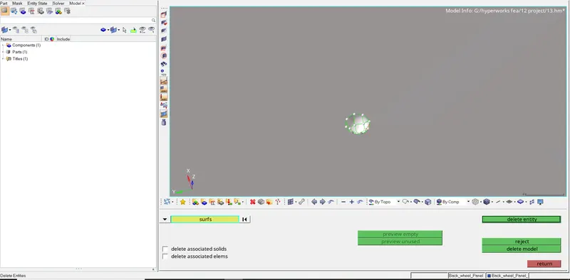
these are really small buttons that are having less size than our minimum size element so we going to delete them with the help of the delete panel where we will select the surface option which will help to delete the surface,
after deleting the button our surface going to look like this and we can't leave it like this so we will create a flat surface over it with the help of the ruled surface tool which we used above
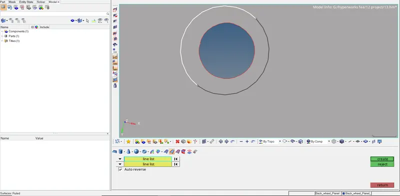
after creating surfaces,
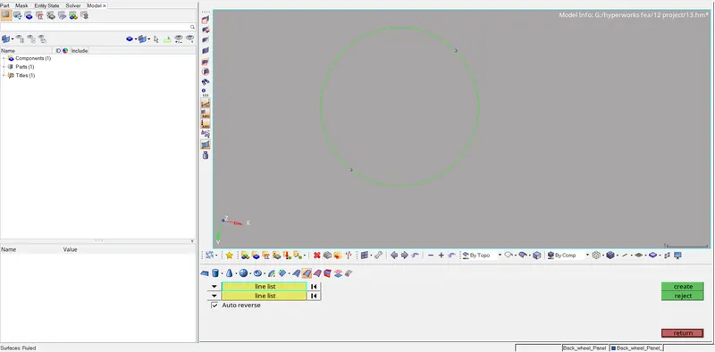
so while meshing simply we can toggle the circular lines so we can mesh easily.
4. MIDSURFACE EXTRACTION
Extracting The midsurface of the given components.
for that first, we are going to measure the thickness of the component.
to measure the distance we are going to use a distance tool where we can locate the points at both the edge point and with that, we can get the distance.
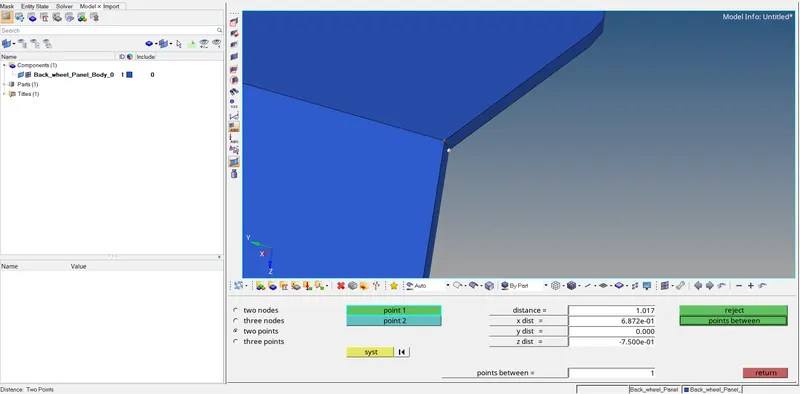
we are using option distance between two points,
DISTANCE>TWO POINTS>POINT 1 and POINT 2(selecting the two points)>DISTANCE(we going to get the value between two points.
the thickness of all the components is 1.017 mm;
one by one we will create mid surfaces for the components.
to create mid surfaces we are using the surface edit tool that we are using in which offset tool we are using.
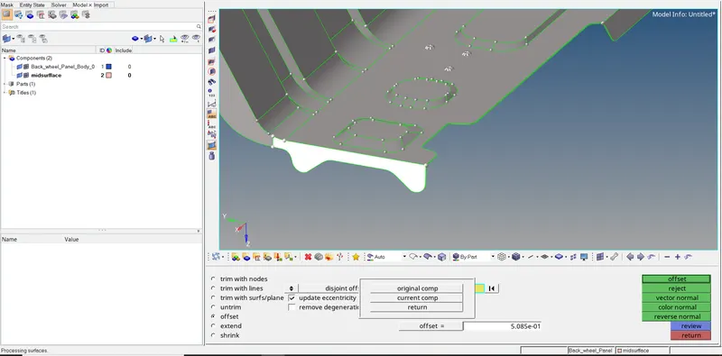
so to use the offset tool we need to create a new component under each component by name manual mid surface to save the newly created mid surface to save these offset surfaces into mid surfaces we need to right-click on it and set them to make current so whenever we will take new midsurface it automatically going to save into it.
so to take midsurface will go to the surface edit tool in which we are using the offset option in which we are going to put half of the thickness value and select or target small regions for midsurfaces of a particular component. after that, we will select the appropriate vector direction in which direction we want to push inside or away from geometry as we are taking midsurface here we are pushing toward the value of half of the thickness. that we can figure out by vector direction
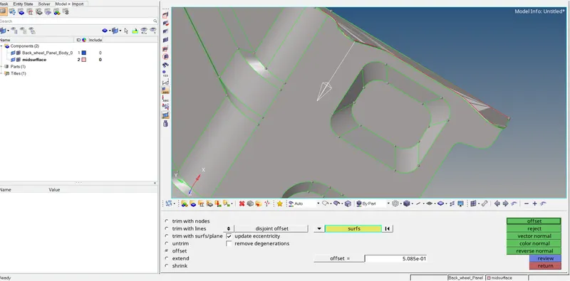
so as we said we are clicking on the surfaces for which we want to create mid surface and below the surface tab, we can select the duplicate option so we can save our mid surface into a particular file of the particular component which is by name of the manual mid surface by clicking on the current component which we changed in the component tree option.
we can see the image below how we took the midsurface of a particular section,
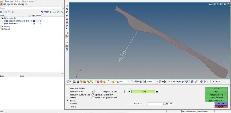
the process we followed,
GEOM>SURFACE EDIT>OFFSET>SURF(SELECTING THE SURFACE AND DUPLICATING IT INTO THE CURRENT COMPONENT FILE)>VECTOR NORMAL(WE CAN CHECK BEFORE WHERE THE VECTOR SHOWING THE DIRECTION OF THE SURFACE WHICH IS GOING TO SUPPRESS SO HERE WE ARE SELECTING THE REVERSE NORMAL )>OFFSET
A similar procedure we are going to do for the whole component is by targeting small areas.
we can see the image below how we applied a similar procedure for all the components,
5. SETTING UP QUALITY CRITERIA FILE:-
we are going to input all the values at their appropriate place to decide values for element failure or to set a range for their failure,
here we using optistruct as our solver so the calculation method will be optistruct and the target element size will be 5 as mentioned
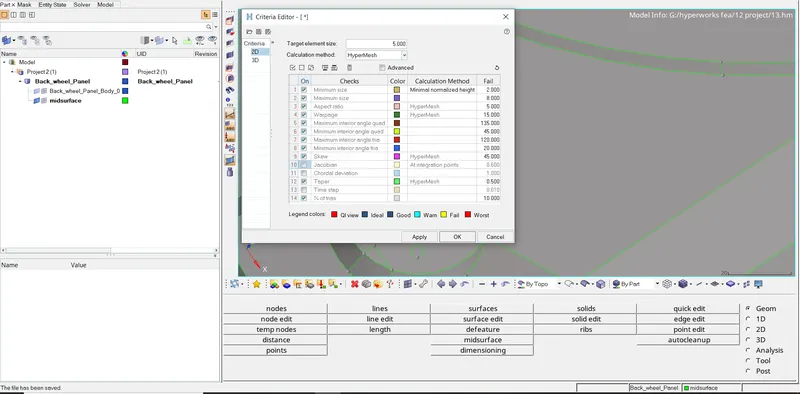
and also other values which defined the quality of elements as mentioned.
6.2D MESHING:-
for that, we will enter into the automesh panel under the 2D panel and will set up all the settings such as element size as 5 and mesh type as a quad and we will select the target surface which we want to mesh, and the mesh will be generated on that surface to get better mesh flow we can change the no of elements on either side by equalizing them we can get quad elements which will help further process for accurate results also we can use smooth option for better mesh flow the main focus will be eliminating the maximum trias as much as possible.
also, we can use the drag tria option under the quality index tool,
we can eliminate trias by opposite trias and rebuilding the elements around them that will help us to eliminate the trias and create a quad element,
also, we can use the combine element option so we can combine two adjacent trias to create a quad.
this method will help us to get the better mesh to flow with fewer trias elements
we can see the image below indicate better mesh flow with no trias as an example,
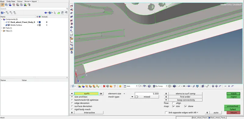
In the image below we can see how we initiated the mesh,
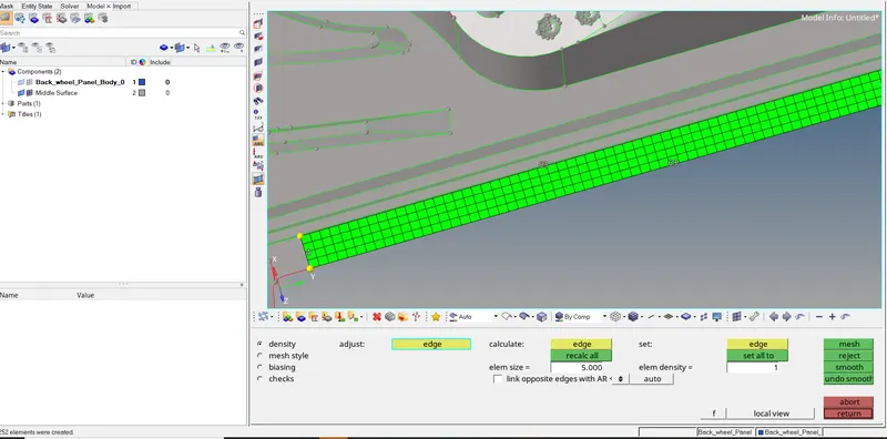
by clicking the middle mouse button will be accepting the mesh to get all the quads we change the no of elements till we get quads to avoid tria elements.
2D > AUTOMESH > SURFACE (desired surface) < ELEMENT SIZE ( element size 5 as given) > MESH STYLE (MIXED) > MESH
there are many other ways to avoid tria or to create a maximum quad element
i. creating a quad element by combining tool
there are two trias adjacent to each other so we can combine them to create a quad by simply selecting two elements under the edit element tool and by clicking on the combine button will result in creating a quad.
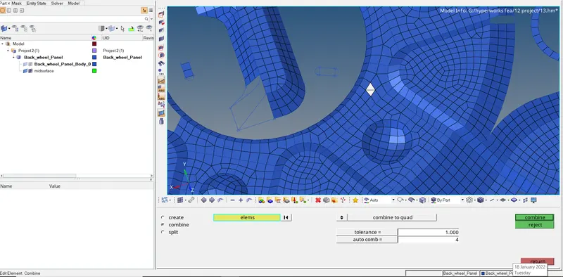
In the image below we can see how we created a quad element,
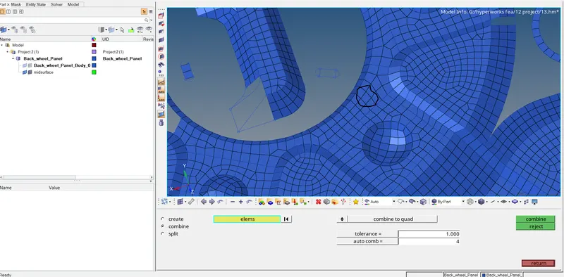
by doing this we successfully created all quad elements and also save elements from failing.
ii. Eliminating opp trias
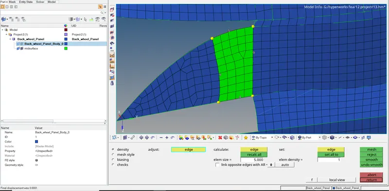
so after meshing almost all the regions we can see there are some trias we can eliminate so the condition below is two opposite trias we can fix this by meshing that region again so here instead of surface here we will use particular elements.
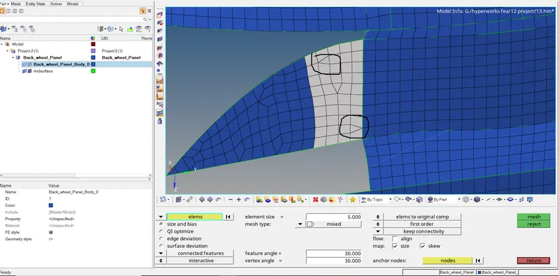
by clicking on the mesh button we can see all the quad elements,
iii. Using mesh style tool
here we are using a mesh style tool where the shapes are complex and we can't simply mesh them by adjusting the no of elements,
so the image below we can see there is a pentagon shape surface and we can see the mesh is not in a good flow so will use the mesh style tool,
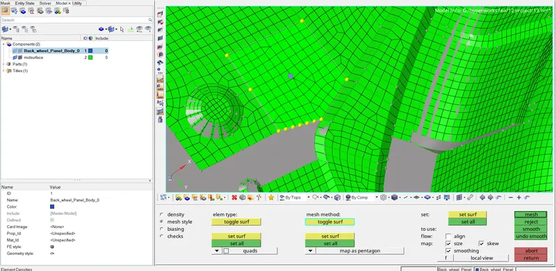
so to begin this procedure we will move to a mesh style tool, and first, match the no of elements of a particular side as it is a pentagon.
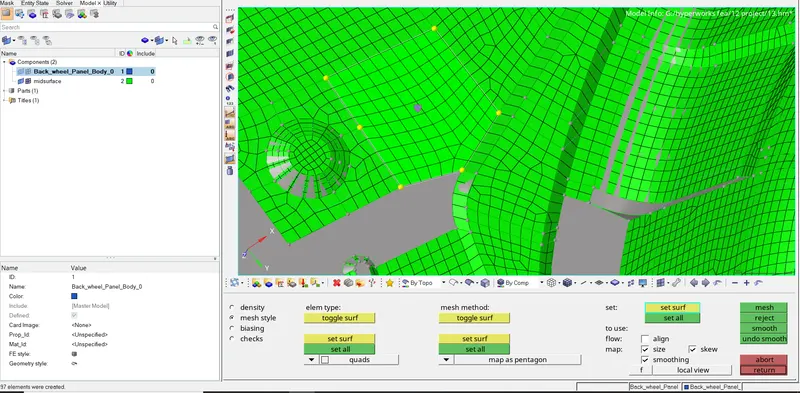
so here we first select the type of element we want which is quad and because the surface is pentagon so we need to map the quads as pentagon by clicking set all on all their green boxes and by clicking on mesh we can see we successfully quad with good flow.
7. QUALITY INDEX
so to access the quality index we will move to the 2D panel,
The Quality Index value is a function of twelve criteria with user-defined weight factors. Each criterion has five rating levels. HyperMesh assigns a penalty value to each element according to its rating for individual criteria.
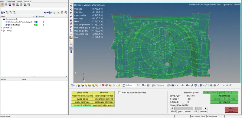
so we can see from the image above that no elements are failing and the no of elements that failed is 58 and obvious the CI is so high because some elements are failing for minimum length and we can't fix them because they are lying in some complicated areas and if we try to fix them will be messing up with our geometry so we are keeping them as it is,
after all this procedure we will move to Assign material and properties to the component,
8. ASSIGNING MATERIAL AND PROPERTIES:-
so to assign material and properties we can simply add material and property by right-clicking into the model tree region
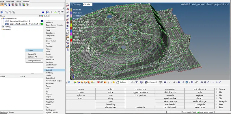
so we successfully added the material and property so will be keeping the values as default values as we only using this for study purposes after adding we need to assign both material and properties to a given component.
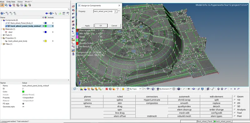
so by right-clicking on the component, we can see, that there is an assigned tool by clicking on that we can see a small window getting pop-up so selecting the appropriate material and property will be clicking on apply button, and hitting ok will confirm the setting.
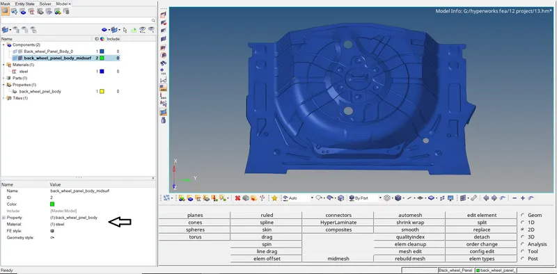
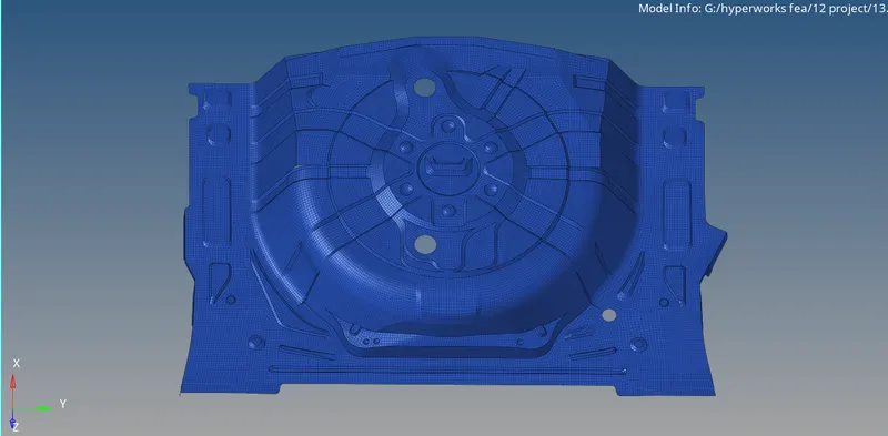
9. RESULT:-
while saving the file we going to save the file in .hm format.
10. CONCLUSION:-
1. we successfully resolved all the geometrical errors.
2. we extract midsurface successfully.
3. we manage to achieve better mesh within the given quality criteria.
4. we assigned material and properties.
(NOTE:- All the files related to this challenge are attached below.)