Week 12:Project 2-Meshing of Rear Wheel Holder challenge
objective:
To perform meshing of the given component using the below-mentioned quality criteria and assign thickness.
procedure:
- Try importing the file given in any one of the formats. The option to import the file varies according to the file format and the file format given here is IGES, the file is imported under geometry file option.
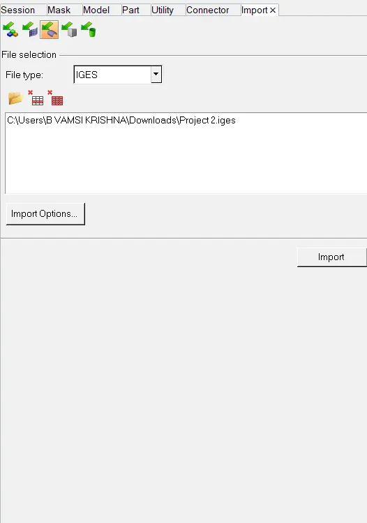
- Soon after importing, the geometry color mode is changed from auto to by topo mode and the surface/solid is visible. If any solid is found it is recommended to delete those and keep the surfaces alone ready for meshing.
- The gemetry is inspected for any errors like free edges, damaged geometry, unnecessary points/connections and if any is found they are fixed using any of the suitable option.
- There are various components in the model and they are organized to a single component collector whereas the unnecessary surfaces are deleted.
- The thickness of the component is measured using the distance option at various points to check if any varying thickness are found in and around the component. As the thickness here is almost uniform of 1 mm and thus the midsurfacing can be made easier.
- The component given here looks symmetrical at certain regions and therefore using the symmetry tool in the surface edit panel the symmetry surfaces are found and the unsymmetrical ones are masked/removed.
- Now the geometry cleanup is performed in the component using the tools in the quick edit panel and the improper/unnecessary surfaces are fixed and the surfaces are made ready for midsurfacing.
- Now the midsurfacing is done using auto midsurface tool or by manual midsurfacing and here after the various inspections the offset+planes+sweep option in the automidsurface tool provides better results. After midsurfacing the middle surface & parent geometry are compared for any missing/improper surfaces and if any are found they are fixed using the offset surface option for manual midsurfacing.

- The midsurface is checked for any errors in the surfaces and they should be fixed up before meshing the component. The geometry cleanup here can be made by using filler, ruled, skin or spline surface depending on the geometry to be fixed.
- In this geometry there are certain spherical/capsule like pin hole structures which are very smaller comparitively and hence those surfaces are deleted and surface filled in those regions.
- Now the process of meshing is started by importing the quality criteria in the criteria file settings and the target element size (5mm here) is also given in the automesh panel. The meshing of the component should be started from the complicated regions/smaller regions such that the mesh flow seems to be uniform and proper till the meshing is done on the component completely
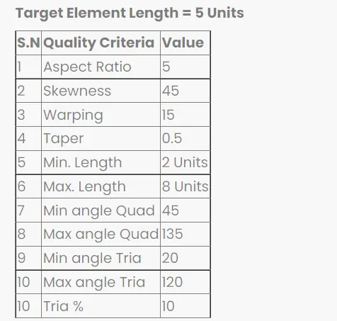
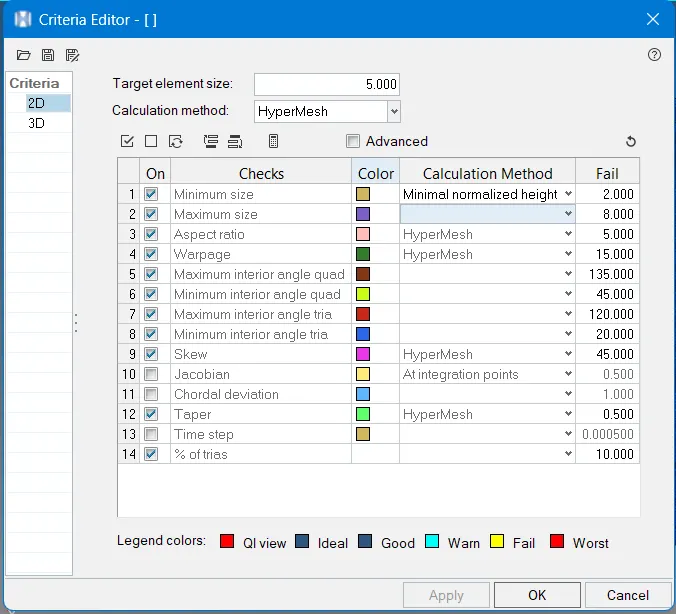
- There are even some other tips to be followed during meshing such as avoiding trias as much as possible, eliminating rotational quads, avoiding high element density, eliminating trias on the free edge or feature edges and so on.
- To make the mesh flow proper the element cleanup tools in the quality index are used and the smoothening of the elements are meshing is more important to get an uniform mesh flow.
- Soon after the complete meshing of the component is done, assigning thickness to the elements in the component is carried out. The thickness of the component is measured and the thickness value is fed in the property panel of the respective component collector. The property collector is then assigned to the component and thus the thickness is visible in the window by enabling the 2D Detailed Element Representation.
- Thus the given component is meshed under the given quality criteria and assigned thickness.
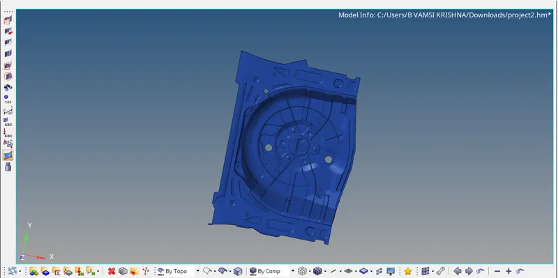
2d traditional element representation
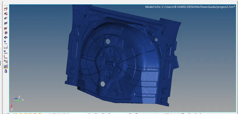
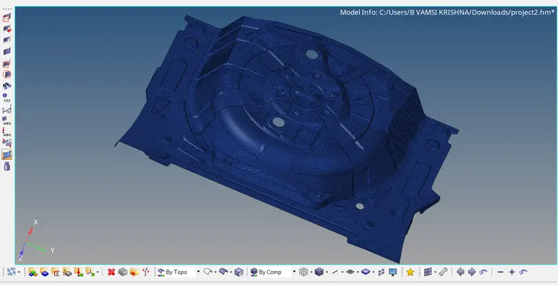
2d detailed element representation:
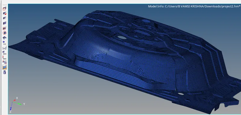
conclusion:
the given model is meshed under the given quality criteria and assigned thickness successfully.