Week 12:Project 2-Meshing of Rear Wheel Holder challenge
PROJECT 2
REAR WHEEL HOLDER
AIM: To perform geometry clean-up and to deploy meshing on rear wheel holder model.
PROCEDURE: 1) Open hyper works student desktop and import rear wheel holder model.
IMPORT GEOMETRY→ SELECT THE FILE TYPE (.iges) → SELECT THE LOCATION → IMPORT
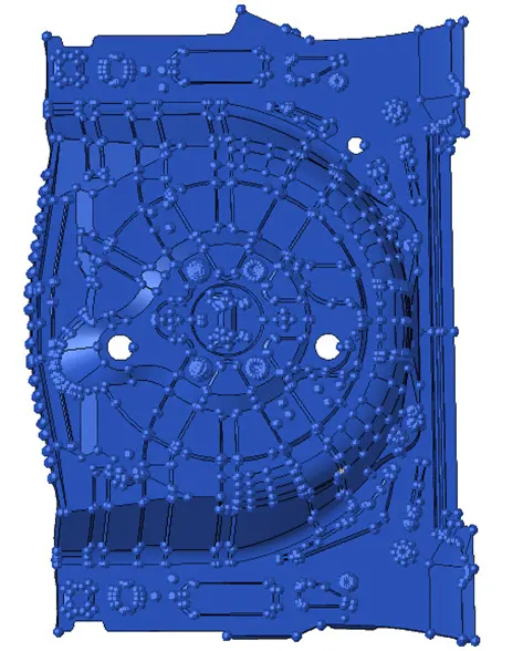
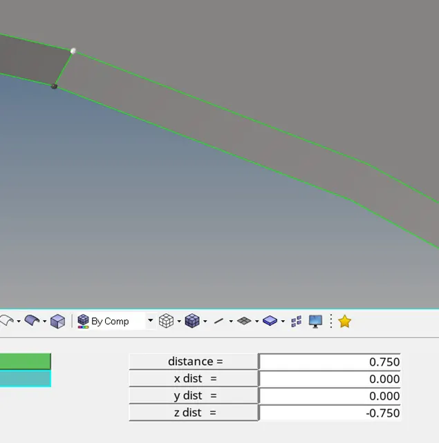
2) Change the mode from auto to topo mode and measure the thickness of the model and different region.
DISTANCE (F4) → SELECT THE TWO POINTS BETWEEN WHICH WE HAVE TO MEASURE THE THICKNESS → OK.
3) Delete the solids.
DELETE (F2) → SOLIDS → SELECT THE COMPONENT → DELETE ENTITY → OK.
4) Now we will create a mid-surface using mid-surface option. Select the extraction option as offset +plane +sweep.
GEOM→ MIDSURFACE→ EXTRACTION OPTION → OFFSET + PLANE + SWEEP → SELECT THE COMPONENT (DISPLAY)→ AUTO EXTRACTION→ CREATE.
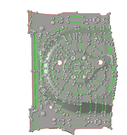
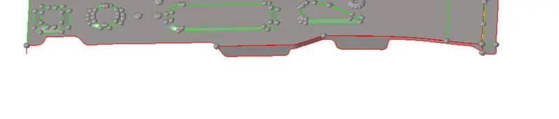
5) Now if we will see in the above images the mid surface is not generated properly. Delete this surface create surfaces using final edit tool option. Rename the collector as mid-surface_0.75.
GEOM → MID-SURFACE→ FINAL EDIT TOOL → SELECT THE SURFACES → CREATE.

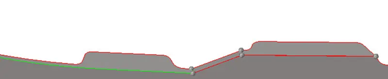
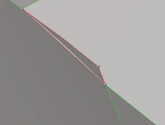
6) Now, using trim with surface and extend option we will create a proper surface.
FOR INTERSECTION:
GEOM→ SURFACE EDIT → TRIM WITH SURF/ PLANE → SELF INTERSECTING SURFACE → SELECT THE SURFACES → OK.
FOR EXTEND:
GEOM→ SURFACE EDIT→ EXTEND → SELECT THE EDGE OF THE SURFACE TO BE EXTENDED AND THE TARGET SURFACE (UPTO WHICH IT IS TO BE EXTENDED) → OK.

7) Now, we will perform geometry clean-up. Delete the duplicate faces and create the missing surfaces.
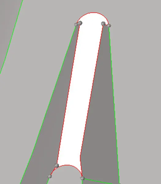
In the above image if we will see the surface is missing. We will create it using surface ruled option.
GEOM→ SURFACE→ RULED → LINE LIST → CREATE.
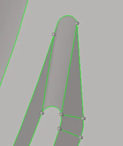
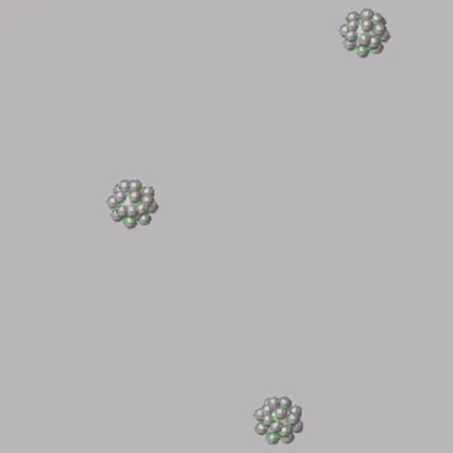
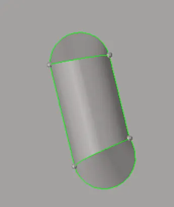
8) Now in the above images if we will see the feature is quite complex and capturing those is difficult task so we will delete those features and will create a flat surface.
DELETE (F2) → SELECT THE FEATURES → DELETE THE ENTITY→OK.
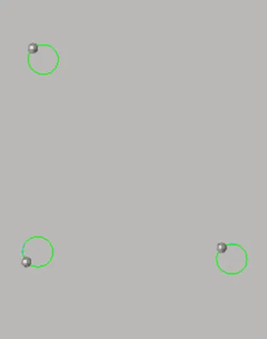
Now fill the surfaces using filler option.
QUICK EDIT (F11) → FILLER SURF→ SELECT THE FREE EDGE → CREATE.
9) Crate property and material card.
FOR MATERIAL CARD:
RIGHT CLICK → CREATE → MATERIAL→ STEEL.
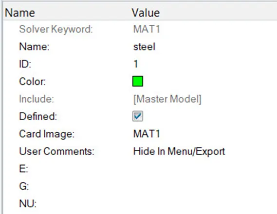
FOR PROPERTY CARD:
RIGHT CLICK→ PROPERTY→ CARD IMAGE (PSHELL)→ ENTER THICKNESS (0.75) → ASSIGN MATERIAL.
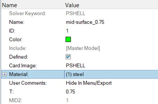
10) Now assign this property and material to the mid-surface.
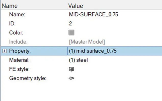

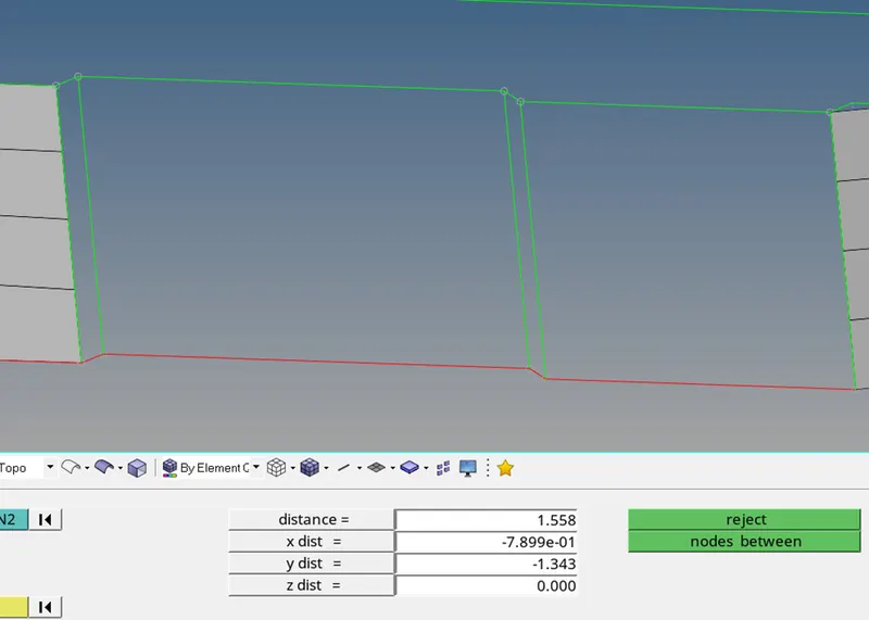
11) Now toggle the edges which is less than minimum length as it will fail for min quality criteria.
12) enter the given quality criteria in the criteria file setting.
PREFERNCES→ CRITERIA FILE SETTING → ENTER THE GIVEN VALUES → APPLY → OK.
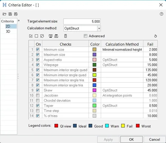
13) Now we will mesh the entire component using auto mesh option.
2D→ AUTO MESH→ ENTER TARGET LENGTH →TICK MARK THE ALIGN AND SIZE OPTION → GENERATE.
Now using different quality clean-up tools like drag tria, swap, place nodes etc. fix all the criteria issues.
2D→ QUALITY INDEX → SELECT THE CLEAN-UP TOOLS WHICH WE WANT TO USE.
NOTE: perform smooth option after using any quality clean-up tool.
Hence, mesh is generated.
14) Now check if there are any free edges or there are any connectivity issues.
Shift +f3 → elements → display→ find edges
Note: while checking for the free edge keep the element colour mode as by comp or by prop and delete the free edges.
Fix this connectivity issues using equivalence option or paste option.
SHIFT +F3→ PREVIEW EQUIVALENCE→ EQUIVALENCE.
Using paste option:
F3 → REPLACE NODE→ NODE TO BE REPLACED WITH → OK.
Now check for the normalcy.
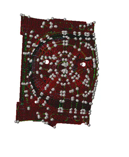
Remember all the elements should have uniform colour or same vector direction. If it is not like that reverse the vector direction using reverse option.
TOOL → NORMALCY→ DISPLAY 2D ELEMENTS→ COLOUR DISPLAY → OK.
Now enabled the 2D detailed mesh option and save the file.
SAVE AS → MODEL→ SELECT THE LOCATION → ENTER THE FILE NAME → SAVE.
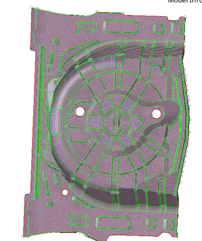
LEARNING OUTCOMES: 1) To generate mid-surface.
2) To deploy mesh.
3) To improve mesh flow.
4) To check for normalcy
5) To check for free edges or element connectivity.
CONCLUSION: Hence, mesh is deployed on the given rear wheel holder model.