Week 12:Project 2-Meshing of Rear Wheel Holder challenge
Meshing Of Rear Wheel Holder
Aim
To mesh the given rear wheel holder model according to the given criteria
Procedure
- It can be observed that the given model has a lot of free edges on the surface.
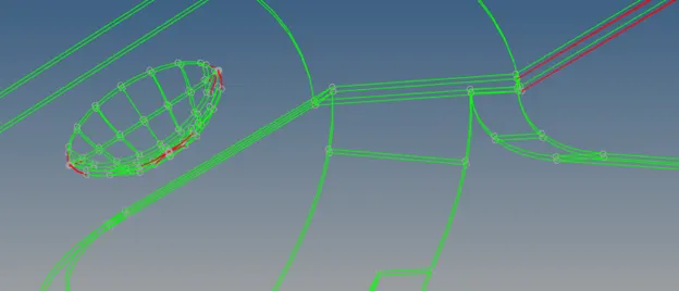
Figure 1
- These free edges can be solved if they are simple but if it is a tedious process, it can be faster to simply ignore them and manually generate the mid surface on such locations and patch them appropriately
- First we use the auto mid surface option to generate the initial mid surface
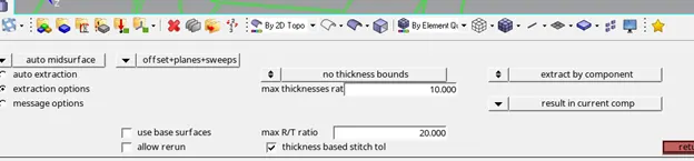
Figure 2
- It is then necessary to manually check the mid surface for free edges and patch them appropriately before meshing.
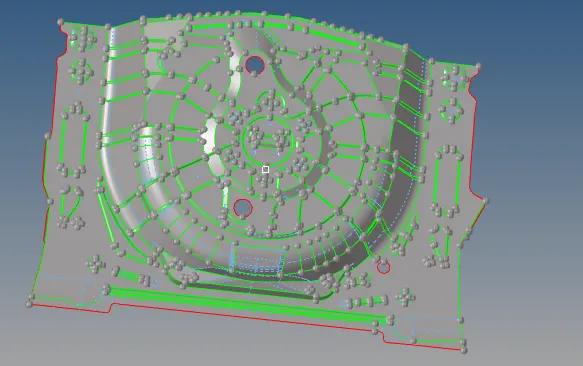
Figure 3
- Also toggle off any unnecessary construction lines as they may lead to bad mesh flow in those areas.
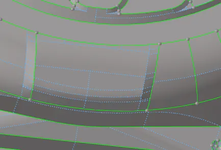
Figure 4
- Certain areas have very small thickness and will fail for quality criteria.It is necessary to defeature such areas
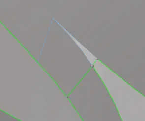
Figure 5
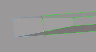
Figure 6
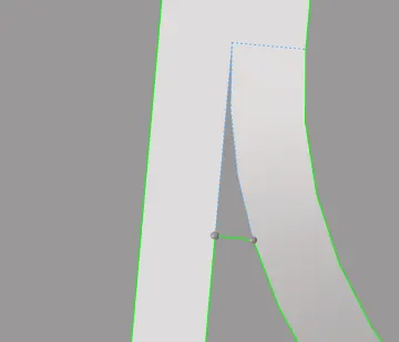
Figure 7
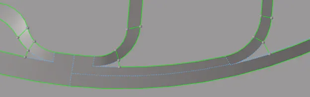
Figure 8
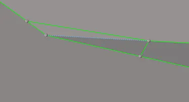
Figure 9
- In these cases making small changes to the feature to capture it approximately while satisfying element criteria will give a better simulation result
- If this is not done, stress singularities will occur in these locations leading to an incorrect conclusion from the simulations.
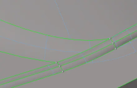
Figure 10
- Areas like in figure 10 were not defeatured as they do not come into contact with significant load and thus will not affect the result of the simulation in any significant manner
Note:These features may be defeatured if required but it is not necessary to do so.
- Criteria required for the mesh is given in table 1 below.
|
S.N |
Quality Criteria |
Value |
|
1 |
Aspect Ratio |
5 |
|
2 |
Skewness |
45 |
|
3 |
Warping |
15 |
|
4 |
Taper |
0.5 |
|
5 |
Min. Length |
2 Units |
|
6 |
Max. Length |
8 Units |
|
7 |
Min angle Quad |
45 |
|
8 |
Max angle Quad |
135 |
|
9 |
Min angle Tria |
20 |
|
10 |
Max angle Tria |
120 |
|
10 |
Tria % |
10 |
- There are 2 possible meshing strategies that can be followed for optimal time save
- One is to mesh half the component and then reflect it since the model is mostly symmetrical outside of certain regions that will need to be remeshed after.
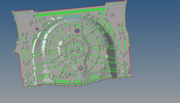
Figure 11
- The other option is to perform batch meshing on the model and then to manually correct the mesh if needed.
- This is preferred if the resulting mesh Quality is acceptable.
- For batch meshing,we need to upload a parameter file and criteria file to hypermesh.
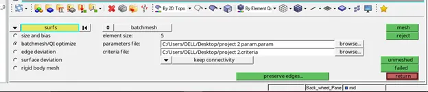
Figure 12
- As we have already done the geometry clean up, we can upload a dummy parameter file.
- In parameter file settings ,in preferences ,disable geometry clean up and upload the file to a folder for access
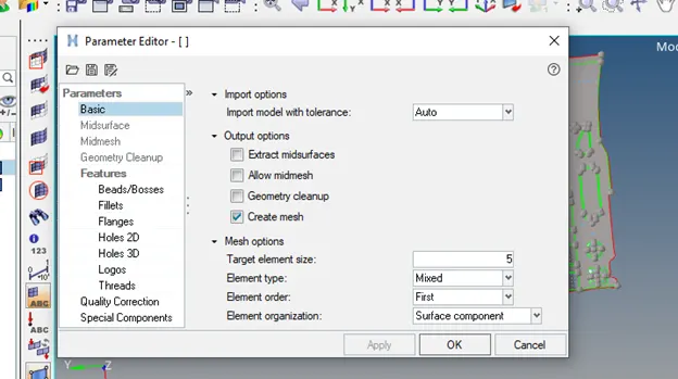
Figure 13
- For criteria file, simply update the values in criteria file settings in preferences to the criteria and upload it in the same folder as the parameter file.
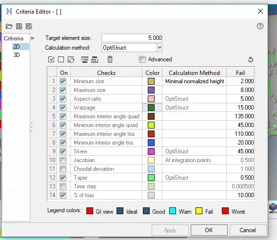
Figure 14
- After uploading the file,select all the surfaces and batch mesh.
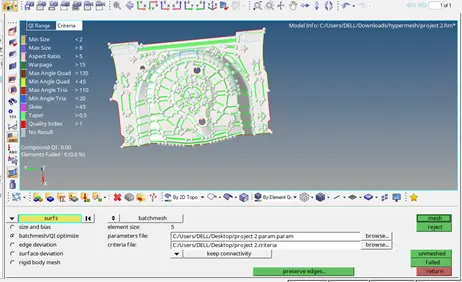
Figure 15
- After batch meshing is completed it is necessary to check each surface manually for solvable trias,off elements and rotating Quads.
Note:If the user has decided to not defeature features the off elements for min length are unsolvable.
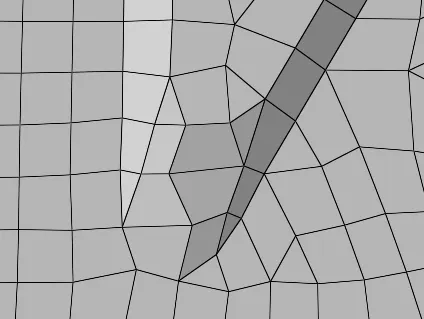
Figure 16
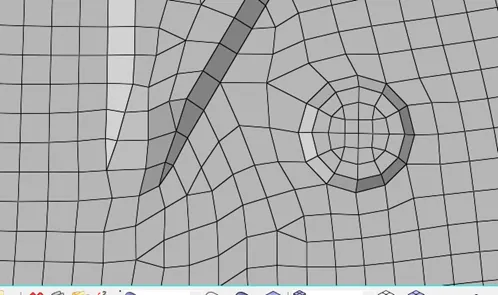
Figure 17
- In the case of figure 18 While it may seem like the trias need to be solved, on viewing the geometry it can be seen that they lie in different planes and hence can be left as is.
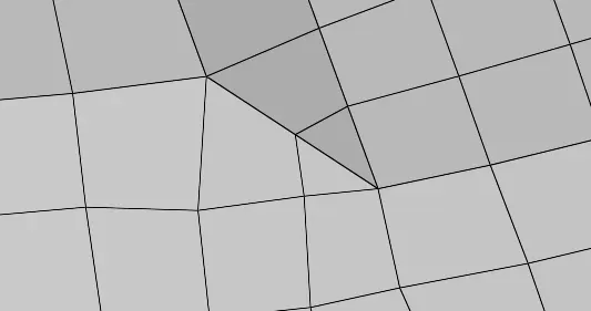
Figure 18
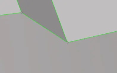
Figure 19
- It can be observed that in certain areas the mid surface extends over the parent geometry or vice versa.
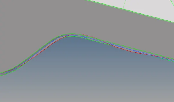
Figure 20
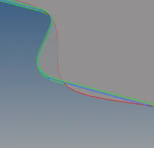
Figure 21
- One option is to extend or trim overlapping surfaces so that the mid surface capture the parent geometry properly
- Another option is to create mid lines and project the mesh accordingly so that the mesh captures the parent geometry properly.
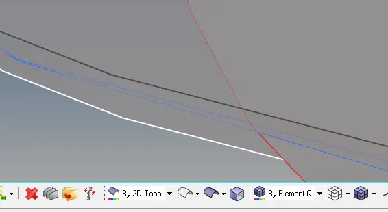
Figure 22
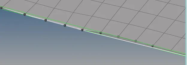
Figure 23
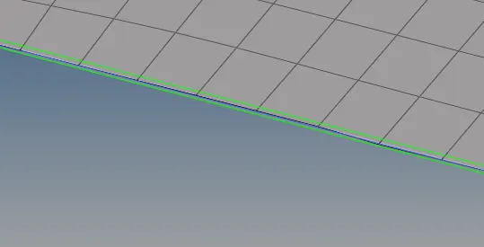
Figure 24
- Final mesh surface
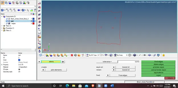
Figure 25
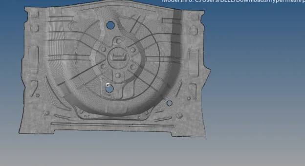
Figure 26
Learning Outcomes
- Defeaturing
- Batch meshing
- Improving batch mesh
- Projecting mesh nodes to mid lines
Result
The model was meshed according to the given criteria successfully.