Week 12:Project-1-Meshing of Door Inner Panel Challenge
AIM: To perform shell meshing on the given side door panel using Hypermesh.
PROCEDURE:
1.Import the model by going to import and select import cad then select the format of the file and click import.
2. Then we need to give the parameters to the component for meshing as per the given data.
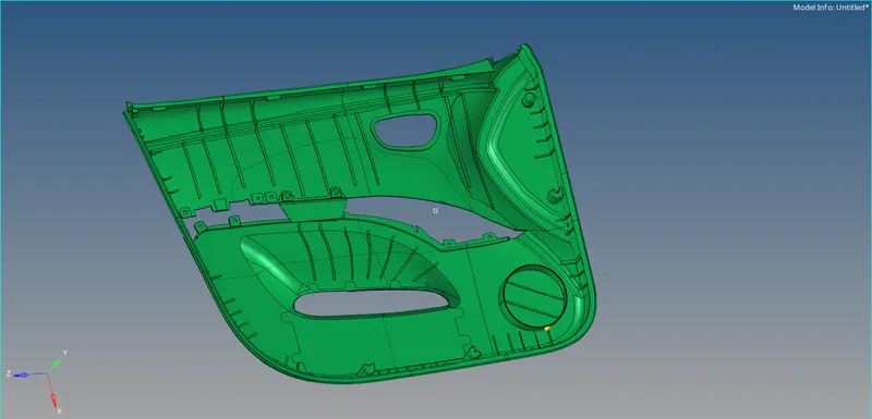
3. To give the parameters we need to go to preferences and select criteria file setting and give the conditions of mesh-like target size. Here we need to specify the quality criteria given to the component. Open the parameter and give target element size and press ok.
4.After setting the criteria, we must take the mid-surface of the component. The component does not have a uniform thickness so we must take manual mid surface for each of the components.
5. In order to make the manual mid surface easy, we must divide the component into four components by using the organize tool which is present in the tools option, and organize the component separately.
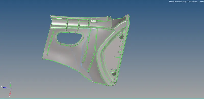
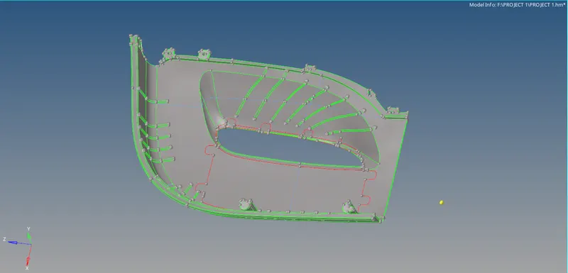
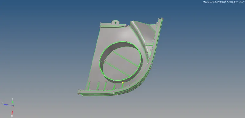
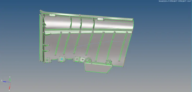
6. Once the surface is separated we can proceed for mid-surface creation, here the auto mid-surface option cannot be used because by the trial and error method we found out that auto-mid did not capture the surfaces clearly so manual mid-surface i.e., offset method is used here.
7. Under the surface edit option available in the geometry panel offset option is available, first we need to measure the thickness of the component using the measure option ( Keyboard shortcut F4 ). Then we need to select the surface to be offset after which the selected surface is duplicated and offset to the new collector created.
8. It can be noted that all four components have the same thickness of 2.8 mm and the ribs present on the surface have varying thicknesses. Also, it should be made sure that the ribs present are extended into bottom surfaces so that while meshing there no chances of element failure.
9. After the geometric cleanup is done we can proceed to mesh, which is available in the auto mesh option in the 2D panel.
10. Meshing is done in each component individually, to achieve proper mesh flow we need to mesh the component section by section which is created during geometric cleanup.
11. After meshing each of the components, we must again organize the individual mid surface of each component to a separate main component and check whether each of the edges is attached properly.
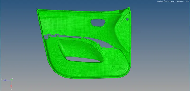
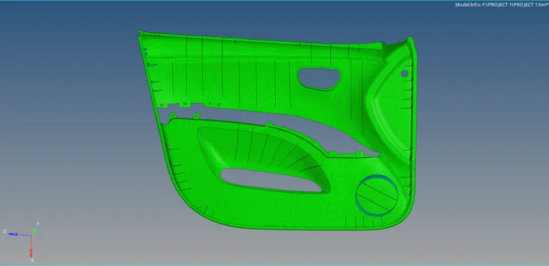

12. To Assign thickness, to the components first, we need to organize the ribs from the base according to the thickness. To do so, the organize option available in the tools panel is used, the rib's thickness is measured and a new collector is created according to the thickness of the ribs.
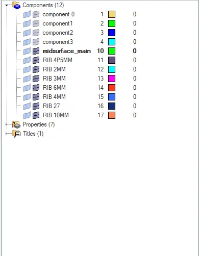
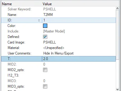
13. To assign the thickness to the component(RIBS), we must create a property bar so that the thickness can be assigned to the ribs.
For simialar ribs separate thickness is assigned (i.e) RIB 2mm, 3mm, 4mm,4.5mm,6mm,10mm,27mm.
14. According to the thickness of the ribs that particular thickness is assigned to the particular component (i.e) 2mm,3mm,4mm,4.5mm,6mm,10mm,27mm.
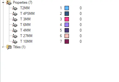
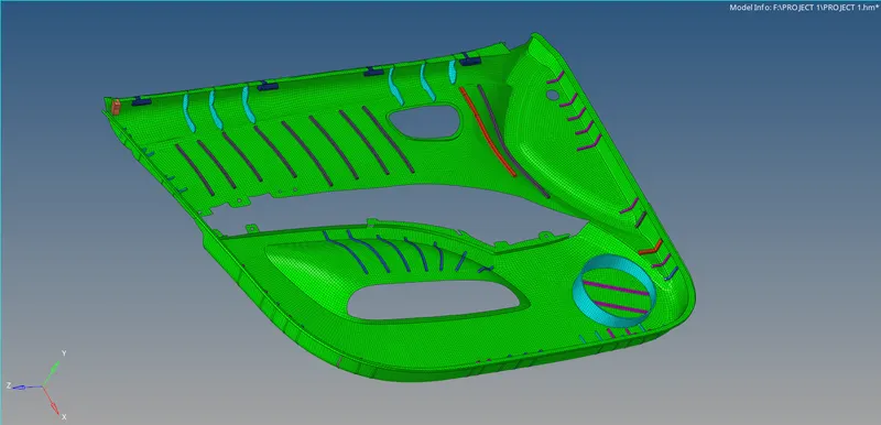
15. After applying the thickness to the component and assigning that to that component we will be able to see the component like the picture which is shown below by viewing the component in the 2D element detailed representation.
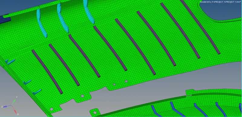
FINAL MODEL REPRESENTATION
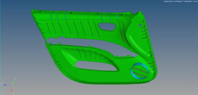
DETAILED MODEL REPRESENTATION
CONCLUSION
Understood the different way of approaching the meshing of a plastic component by meshing the given side door panel with all elements clearing the quality and thickness is assigned with smooth mesh flow.