Assignment 2-RADIOSS Engine File Editing & 3D Meshing Challenge
1.Check the material properties of the rail component and calculate the speed of sound in steel rail=
Elemental Time Step= `Delta`tc=(L/C)=(L/`root`(E/`rho`))
From the given Radioss file, we have obtained the value of density and youngs modules was obtained
E= 210000, Rho= 0.0078
Substituting the value of the equation C = (`root`(E/`rho`)
C=`root`(21000/0.0078)
C=5188.74
2.From the given data we know that length of the rail is 1000mm. The Time taken for the shock wave to travel from one point to another point can be calculated by using the elemental time step equation
Elemental Time Step= `Delta`ta=(L/C)=(L/`root`(E/`rho`))
`Delta`tc=(L/C)
`Delta`tc=(1000/5188.74)
`Delta`tc= 0.19272
3.The Time Taken for traveling the rail is= 0.19272
4.In the engine cards the runtime is given as 0.19272 (set on/RUN card) so that the stress wave can be monitored, moving from one end of the rail to the other during an impact -this will require a termination time equal to the time it takes for the sound to travel the length of the rail.
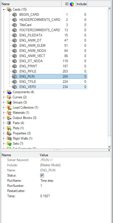
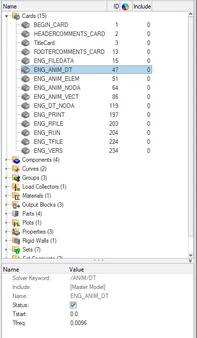
5.The frequency of animation output to a time that will give 20 animation steps(/ANIM/DT)
frequency=Termination End time / Steps Required
frequency=0.1927/20
f=0.009635
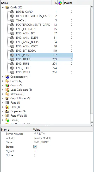
6. Change/Print= -10
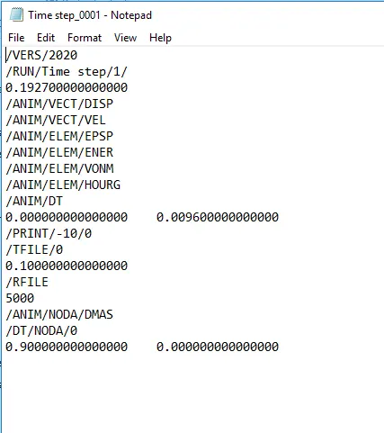
7.After editing the values the Status is checked and exported as a new folder or overwritten with the same engine file and checked with the previous data.
7. AIM:
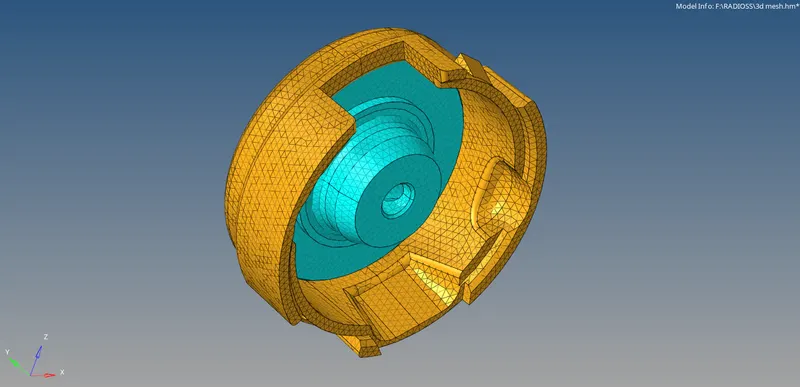
To Generate 3D tetra meshing on The Given Housing model And to check for The Tet collapse and quality.
PROCEDURE:
- The Given Housing Model was Imported in the new file format in the radioss block.
- The model consists of two components hub and cover and we separately perform meshing for each of the components.
- First, we perform 2D meshing on the two separated components by only using the tetra mesh which is present in the auto mesh panel.
- Then 3d meshing was performed in the 2d face of the components and 3d parameters were given to the components.
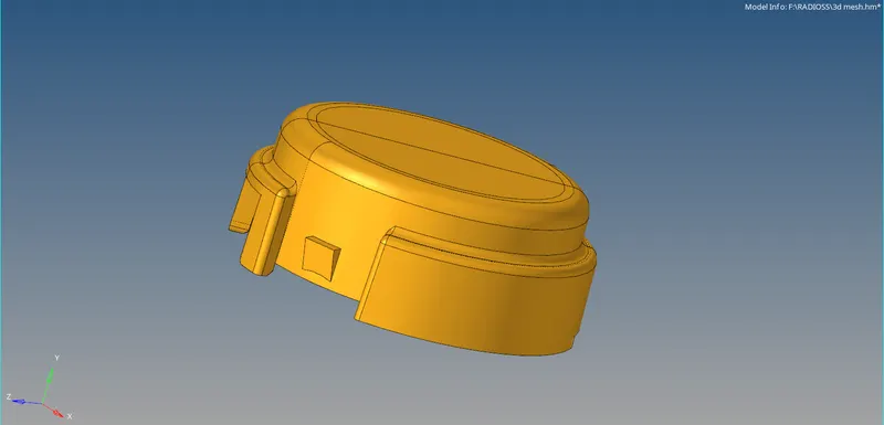
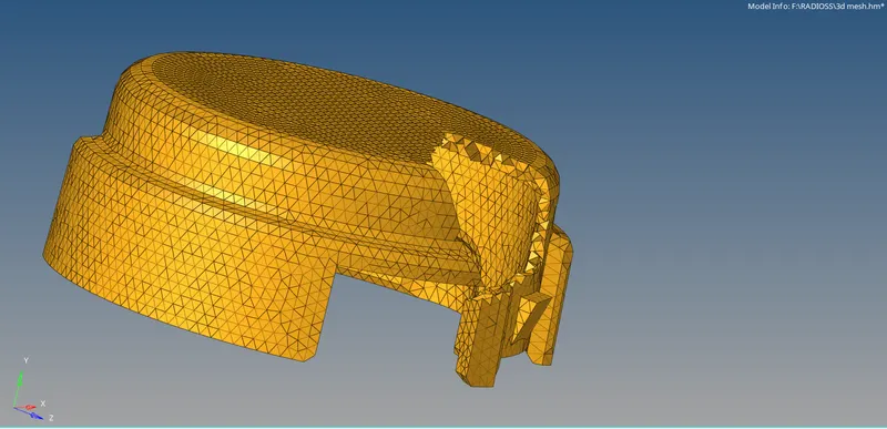
- To ensure the elements are properly meshing, with the help of the mask option(F5) is used to see the 3D formed elements.
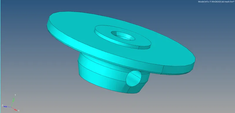
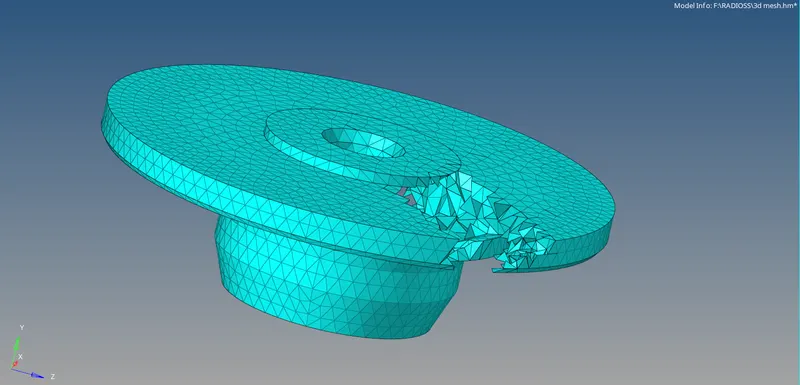

- After that quality was checked in the Check elements pannel by giving the set of conditions given in the Model.
- The Tet collapse Is checked finally after meshing And it's ensured that no elements are failing for Tet collapse.
CONCLUSION:
From the above model, I gained knowledge about performing 3D tetra-meshing using the given quality criteria.
8.AIM:
3D-Hexa meshing the arm Bracket according to the given parameters.
PROCEDURE:
- The Given Bracket Model was Imported In a new Radioss block format.
- The Arm Bracket Is divided into 4 components, hide All the components except the one to mesh.
- The 2D mesh was Generated over the Base first with the element Size 5.
- The elements are remeshed And Made sure that there is no Trias and Rotating quads.
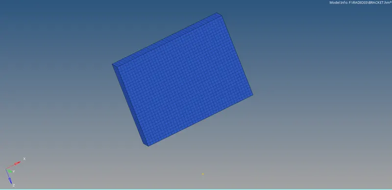
- To convert the shell into 3D element offset option was used here as the component is uniform square, from The 3D panel 3D> Element Offset.
-
After completing meshing, the component is hidden, arm curve is made to show with boundaries of previous base model.
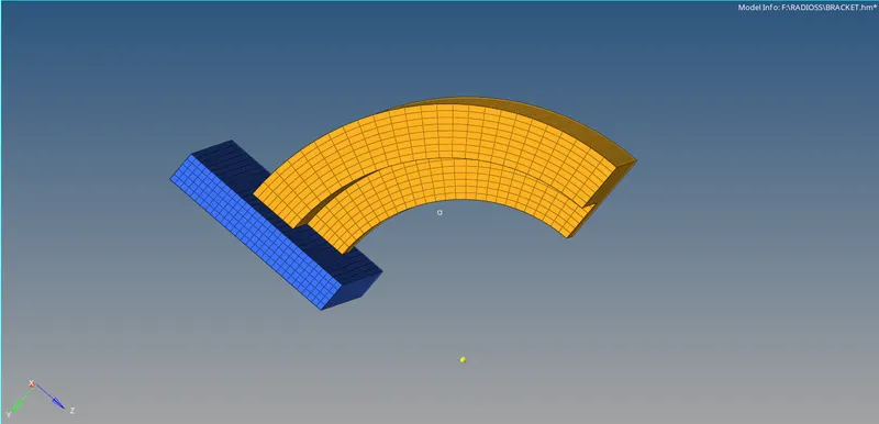
- since the arm curve is in the form of a circle a center node is created by using the ARC center option in the nodes Panel by selecting any lines in the arm curve
- 3D > Spin Option is used to create the mesh by spinning the Element across the Arm curve by using Shell Elements by considering the node at the center.
- Select Spin Elements > 2D Shell elements > Y axis > Base point as centre node of the arc > Angle 90 > Spin Density of 25 (layer of elements) > Spin.
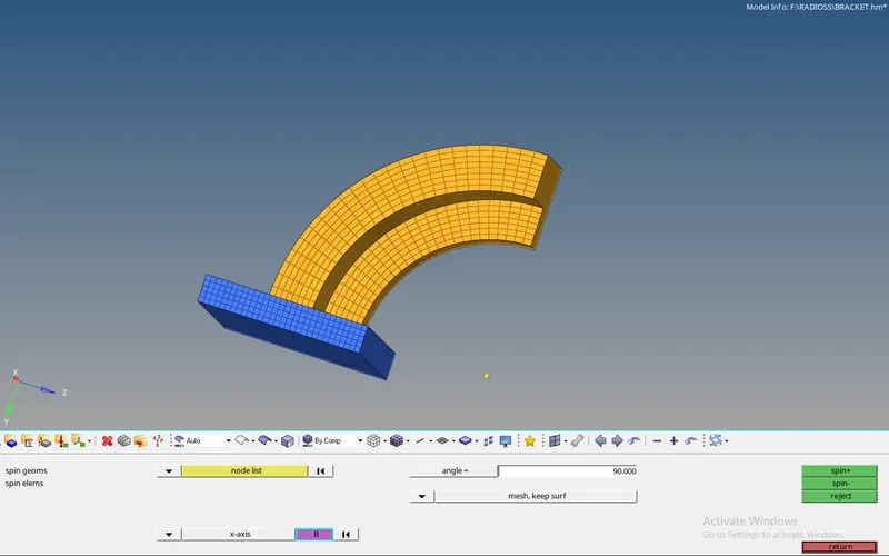
- After spinning the elements formed are 3d elements so for creating shell elements face was created over the Arm curve by using Tool> Faces> find faces and the face of the Arm straight is meshed with 2d mesh.
- The no. of elements in the face of the arm curve should match with the no of elements in the arm curve. Thus It form a shell layer between both the components.
- Select the Linear solid > Select the elements on arm curve face > Node points which are to be selected in the same manner on Arm straight Mesh and assign the density as 15 and choose solids. Hide the Arm straight part, make Boss the current component.
- The 2D mesh was Generated over the Boss and elements are matched accordingly. Nodes are projected in equal line at the joining of arm straight and the boss using the project point option from F11.
- Choose> soid map>general from the 3D pannel.
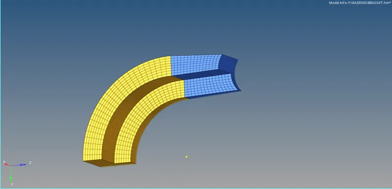
- Select Elements to Drag > To The source Surface >By the Node Path so the connectivity will be equal and create the mesh.
- Hide the Arm straight part, make Boss the current component. The 2D mesh was Generated over the Boss and elements are matched accordingly.
- Nodes are projected in equal line at the joining of arm straight and the boss. using the project point option from F11.Choose> solid map>general from the 3D panel.
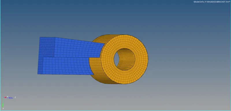
- Select Elements to Drag > To The source Surface >By the Node Path so the connectivity will be equal and create the mesh.
- After verifying the connectivity delete all the faces and turn on all the geometry.
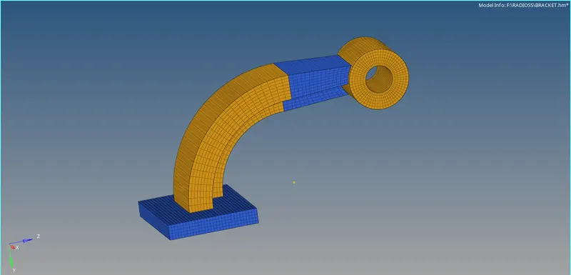
CONCLUSION:
From the above model, I was able to gain knowledge of performing 3D hexa meshing.