Week 12:Project-1-Meshing of Door Inner Panel Challenge
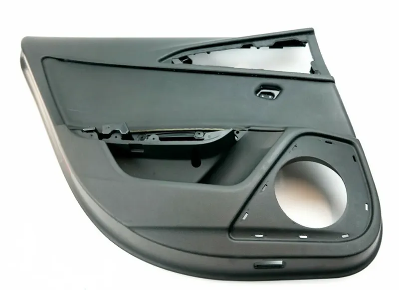
Car Side Door Panel
The side door panel is the plastic part. materials used for the door panel are acrylonitrile-butadiene-styrene (ABS), ABS/polycarbonate alloys, Polypropylene (PP).
Properties
- High weathering resistance
- High strength and toughness up to 140°C
- Very good heat resistance
- good processing characteristics
- Remail flexible down to -150°C
- High rigidity
- Good impact resistance
In the fig0.2 Shows the example for the side door panel.
- Finite Element Analysis
The finite element method is a numerical technique for obtaining an approximate solution to a wide variety of engineering problems. FEA (Finite Element Analysis) is done by three phases.
- Pre-processing
- Solution
- post-Processing
This project comes under Pre-processing. The goals of Pre-processing are to develop an appropriate finite element mesh, assign suitable material ID and boundary conditions. ANSA And Hyper-mesh are the example tools and in this project Hypermesh is used.
Element Quality Criteria:
|
S.No |
Quality Criteria |
Value |
|
1 |
Target/Average length |
5 |
|
2 |
Minimum Length |
2 |
|
3 |
Maximum Length |
6 |
|
4 |
Aspect |
5 |
|
5 |
Warpage |
15 |
|
6 |
Skewness |
45 |
|
7 |
Minimum Quad Angle |
45 |
|
8 |
Maximum Quad Angle |
135 |
|
9 |
Minimum Tria Angle |
20 |
|
10 |
Maximum Tria Angle |
120 |
|
11 |
Tria Percentage |
10 |
|
12 |
Taper |
0.5 |
Procedure:
The meshing is done by following steps
- Import side_door_panel.hm in to Hypermesh
- CAD Geometry clean up and topology
- Mid-surface extraction
- Defeaturing
- Shell meshing
- Creating properties and Thickness assigning.
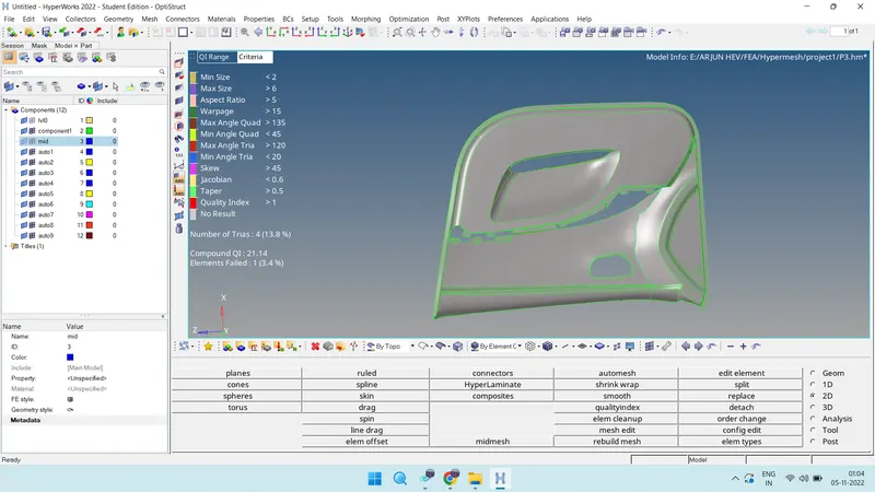
- Import Side_door.hm in to Hypermesh :file>open>model, browse the file and open. in the figure 1.1 shows the model.
Tools used in topology
Tools>Edge Edit Panel
A. Equivalence (multiple edges at a time) Search surfaces for pairs of free edges and combine into shared edges
B. Toggle (edge pair at a time) Select an edge; equivalences with other free edges found within a user specified tolerance
C. Replace (1 edge pair at a time) Select 2 edges to equivalence together. Control which edge to retain and which to move.
D. Geom>Surfaces>Ruled or Geom> Quick edit > filler surface or 2d> spline> surfaces only (to create missing surfaces).
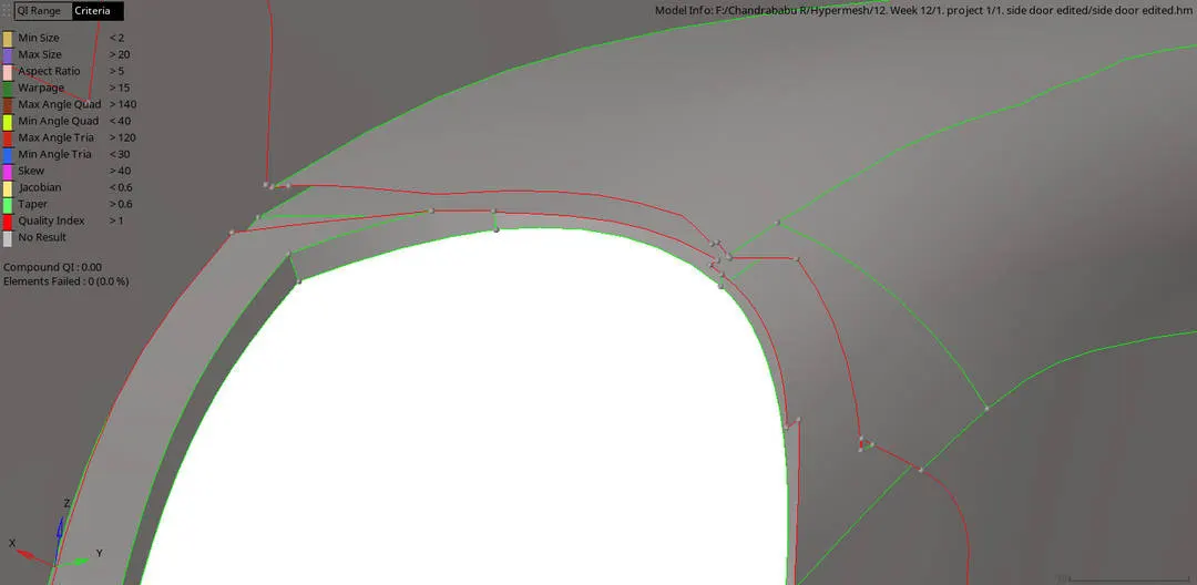
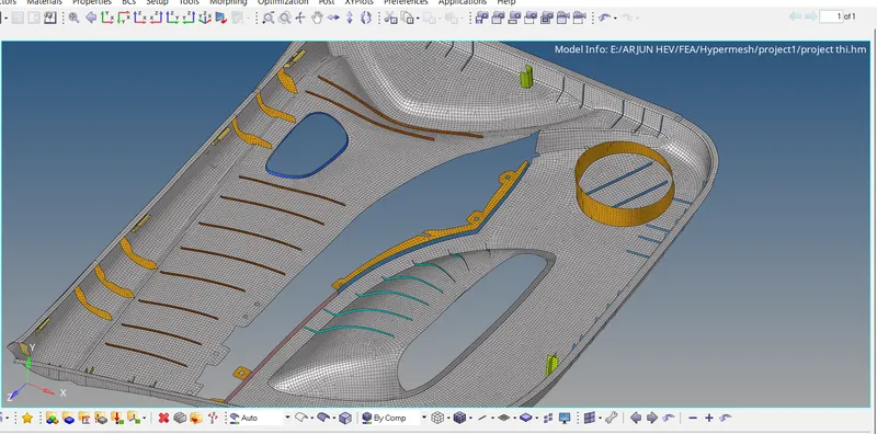
In the given model there are so many defects. fillets which are very small and should be defeated. In the fig. 2.2 shows some defects.
- Clean up the geometry of the components for obtaining better mid-surface.
- Now, after checking the thickness at various points of the components by Geometry > distance > two points, it is found that the component has varying thickness. So, manual mid-surfacing is done by going to Geometry > surface edit > offset. Then, select the surface and duplicate it, specify offset thickness and click offset and the mid surface is created.
To create the mid surface of the ribs, go to Geometry > midsurface > final edit tools > surface pair, select the surfaces and click extract.
- can be replaced with the ribs free edge by Geometry > edge edit > replace.
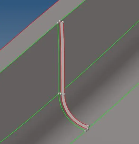
There is also a cylindrical surface which can be done in the same procedure.
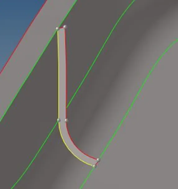
There is also a cylindrical surface which can be done in the same procedure.
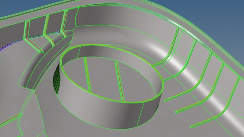
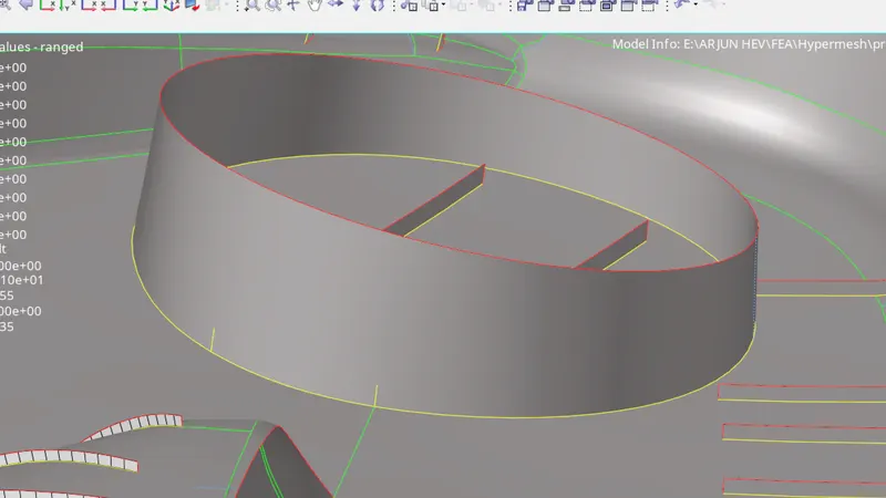
After extracting the mid-surface, perform the geometry clean up. Then, the mesh can be created by 2D > automesh > size and bias. Then, assign element size, mesh type , select surface and click mesh.
Meshing.
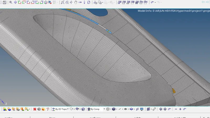
The obtained mesh fails for quality criteria which can be corrected by remeshing with 2D > rebuild mesh ad select edit criteria. A window is opened where quality criteria requirements can de given. Then, select the elements and click rebuild. If the mesh still fails select the elements and remesh it.
Check for the failed elements
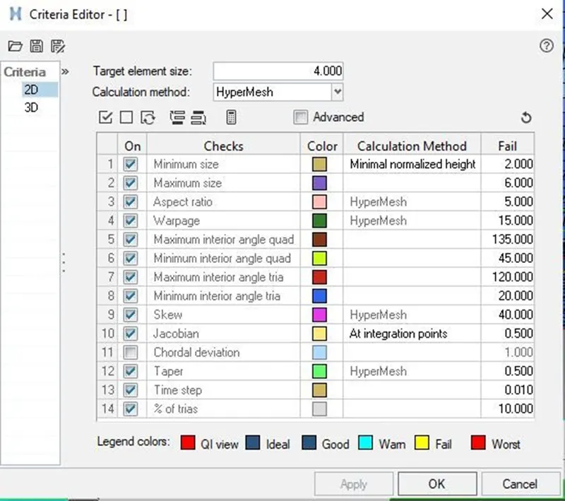
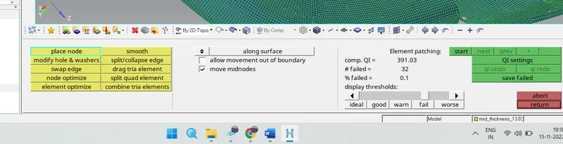
After applying qaulity criteria failed elements should be corrected by the help of Qaulity cleanup tools.
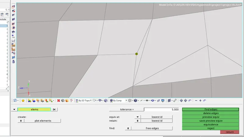
Also check for connectivity by Tool > edges, select the elements and click preview equivalence. This can be corrected either by clicking equivalence in the same menu or by manually through 2D > replace and selecting the nodes to replace.
Assign thickness:
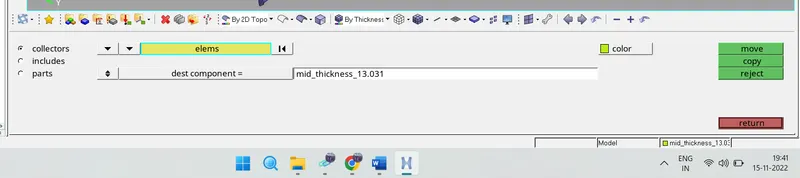
Since there are surfaces and many ribs with varying thickness, arrange the elements with same thickness to the same component by Tool > organize, select the elements and click move.
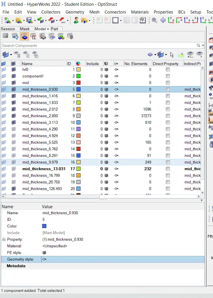
Then create property cards for all the thickness and assign it to the respective components.
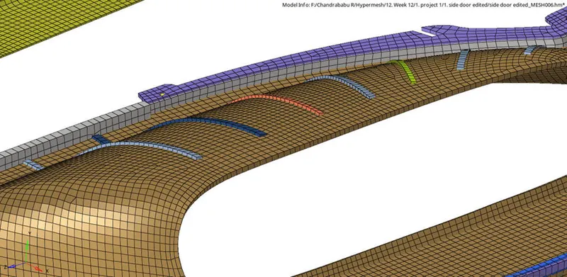
As we assigned thickness ther ewere lot of variation in thickness so we orgenize th ethickness manually by using orgwbize option.
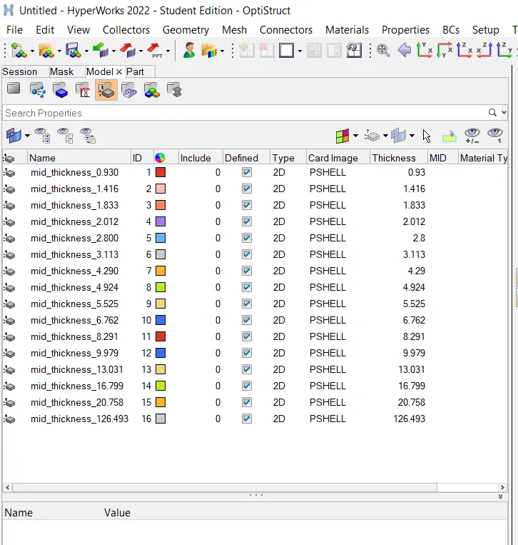
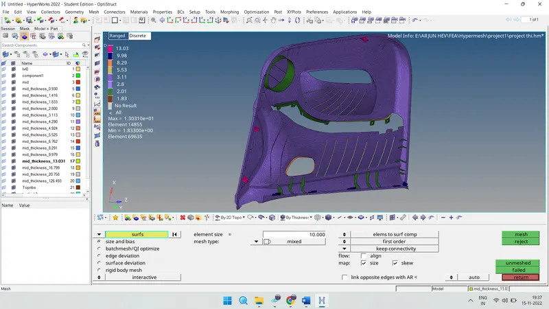
Final part with ssigned thickness.
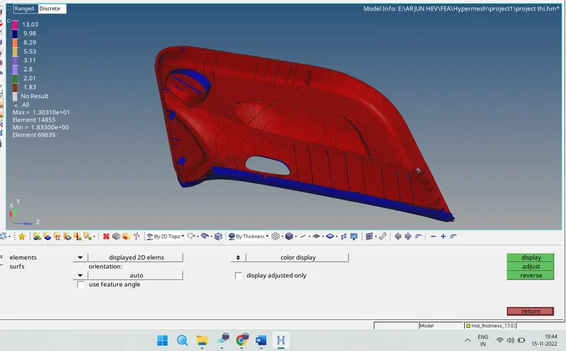
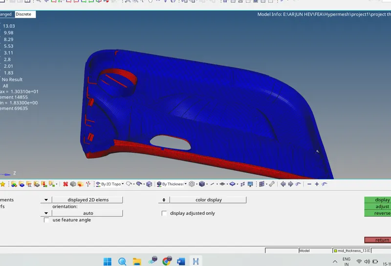
Check for normals: use the Normals panel to display and reverse the normals of elements or surfaces. The orientation of element normals can also be adjusted. The normal of an element is determined by following the order of nodes of the element using the right-hand rule.
Steps
- Use the Elements subpanel to display and reverse the normals of elements. Select elements indirectly by components or directly by elements, or elect to have all of the displayed 2D elements selected automatically. Click displayto review the current normal orientation of the selected elements. Optionally, click reverse to flip the normals to the opposite side (reverse the normals).
RESULT:
The given is meshed property with the given quality criteria requirements and the correct thickness is assigned the respective elements.