Week 12:Project-1-Meshing of Door Inner Panel Challenge
Objective-
Follow the Quality Criteria and mesh the following component and assign thickness:
Target Element Length = 4 Units
| S.N | Quality Criteria | Value |
| 1 | Aspect Ratio | 5 |
| 2 | Skewness | 45 |
| 3 | Warping | 15 |
| 4 | Taper | 0.5 |
| 5 | Min. Length | 2 Units |
| 6 | Max. Length | 6 Units |
| 7 | Min angle Quad | 45 |
| 8 | Max angle Quad | 135 |
| 9 | Min angle Tria | 20 |
| 10 | Max angle Tria | 120 |
| 10 | Tria % | 10 |
Procedure-
1.Import the given model in Hypermesh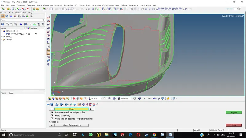
2.As we can see there are some surfaces missing.Here, the approach would be to offset the other side of the component as it does not have any complicated features attached to it & we can easily project the features present on other side to this side.
3.This will save a lot of time & we wont be working on the parent geometry as the damaged surfaces are only on one side and we can easily offset the other ignoring the damaged surface.
4.Measure the distance between the upper and lower surfaces at multiple points and we can go to surface edit>offset to offset the surface.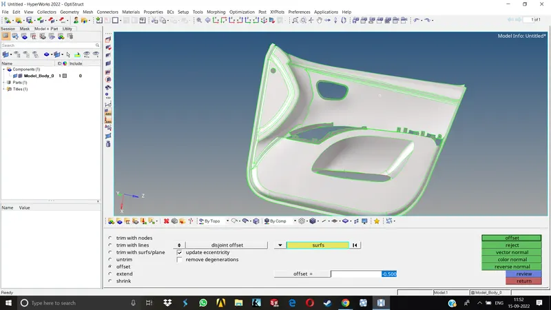
5.NOw the next step is to take mid of the small features and project them to the base midsurface.
6.Before directly going for mid of the features, we can observe that there are a lot of small features containing fillets which are relatively smaller than the min element size, they will definitely fail for the min length criteria which is 2 mm here.
7.We need to delete all these small fillets which are under 2mm. Go to Geometry>Defeature>Surface filets, 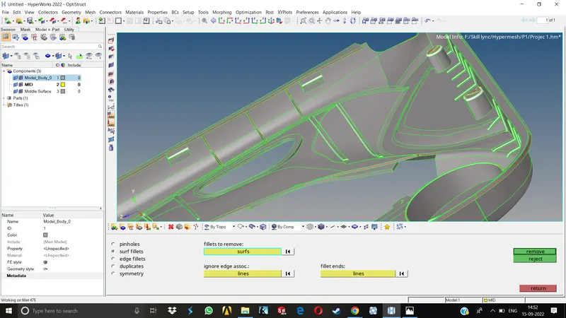
we can specify the max and min fillet radius there and hypermesh will make a selection of those fillets on confirming, after the selection, delete those fillets.
8.Now we can proceed for feature capturing. As mentioned in the question, we need to capture the dog houses as cross shaped surfaces, as they have higher thickness & we need to model them in 2D mesh only as specified.
Midsurface for the features-
1.We need to create two lines in cross shape across this feature, go to Geom>lines > with linear nodes.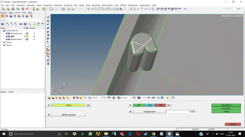
2.NOw form the nodes by long pressing the right click & drop the click where you want the node to be, once the nodes are formed, we can connect the lines to form a cross shape.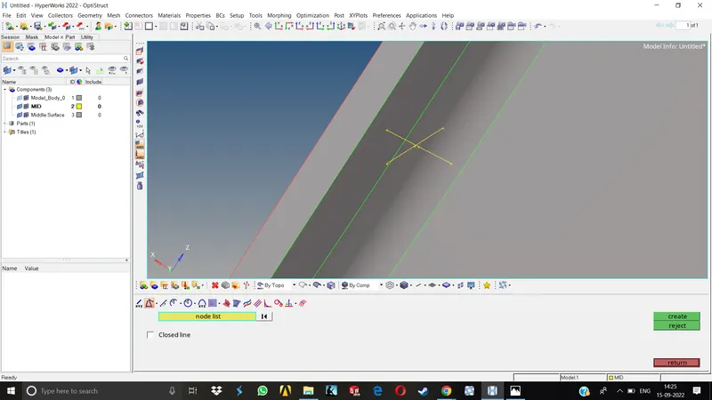
3.Go to Tools>Translate , select the two lines, duplicate them in the current component and translate them below the midsurface itself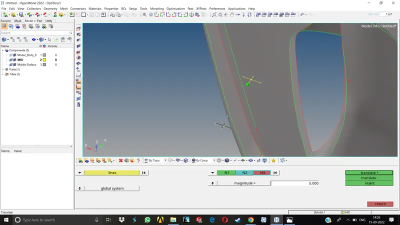
4.Go to surface> ruled and select the line pairs one by one to form the surface which will be intersecting the base midsurface
5.NOw go to surface edit> self intersecting surfaces> select the intersecting surfaces and trim, delete the extra surfaces.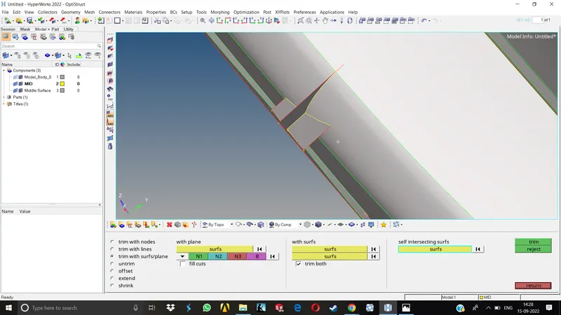
We will follow this same procedure to capture the similar features.
6.For capturing the fillet regions, go to Geom>Midsurface>Final edit tools & select the surafce pairs to automatically generate midsurface between them.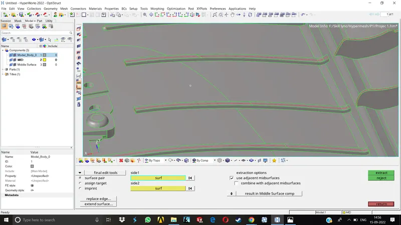
7.Once all the small features are captured, we have to project these to the base midsurface. For doing so, go to surface edit>Extend surfaces select surfaces to extend & target surface and click extend. The surfaces then will get extended.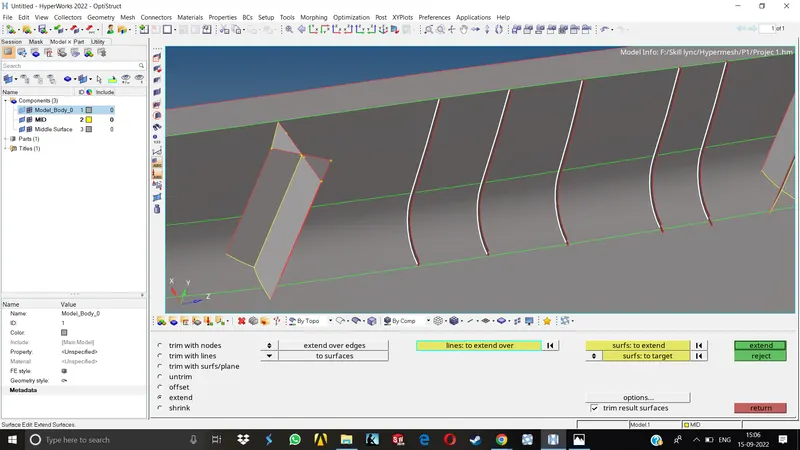
Surface preperation for Meshing-
1.To get a good meshflow, we have to split the geometry accordingly.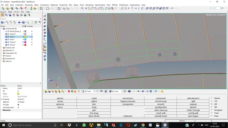
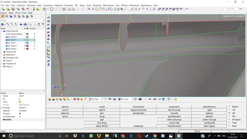
2.We need to toggle the lines which may result in quality errors, we might need to replace some points, trim off some unwanted surfaces, delete some extra nodes formed in all the areas etc. 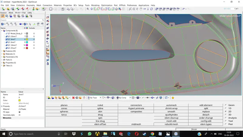
Meshing-
1.once the midsurface is created, we can proceed to meshing, first we need to setup the criteria for mesh as specified.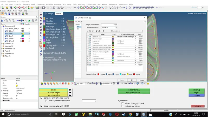
2.Now we can either batchmesh the whole component or go with the manual meshing.Here, we have tried both.The batchmesh produced a lot of trias as compared to manual meshing.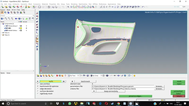
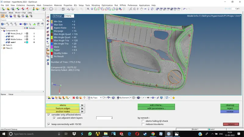
3.In manual meshing we can go from surface to surface, correcting and improving the mesh simultenously, obtaining a better mesh flow and low tria concentration.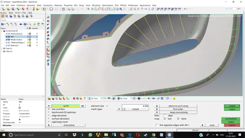
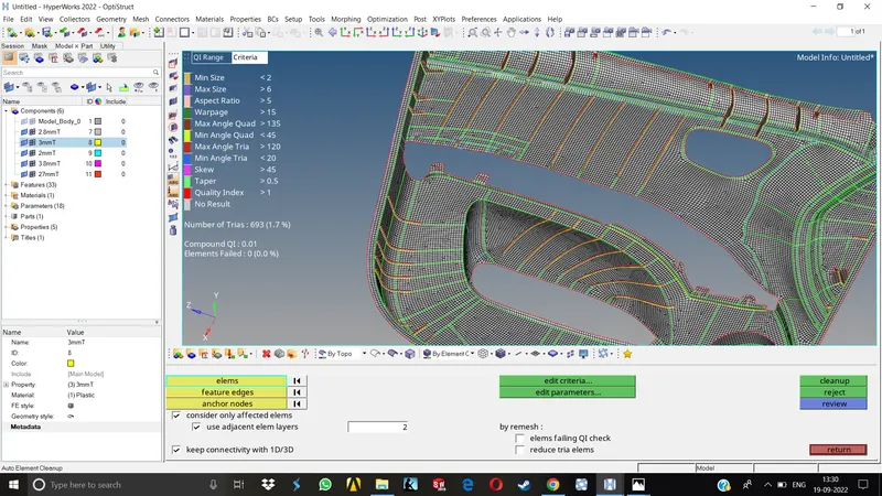
4.We need to follow the Qc while meshing and the failing elements are dealt with accordingly.
5.In some areas, we need to replace nodes, align nodes, remesh the failed area, smooth, optimize the nodes & elements, use the element cleanup tools, etc.
6.Once all the failed elements are resolved, we can now assign thickness to the elements.
Thickness Assignment-
We can either use midmesh thickness to assign thickness automatically to all the components, or go with the manual method. Here we have tried both of them and kept the one which gave us superior results.
Automatic Thickness Assignment-
1.Go to Mesh>Assign>Midmesh Thickness, make the selection window for selecting surfaces and select all the surfaces in parent geometry. 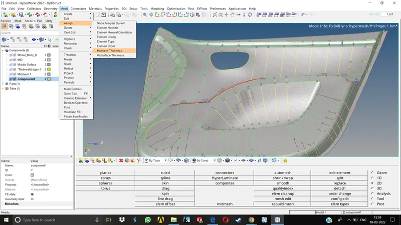
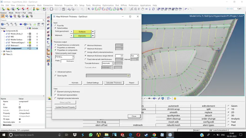
2.Once all the surfaces are selected, we need to select all the elements.Now select the thickness output to Properties on components as it will create a separate components for different thicknesses.
3.We can keep the max thickness range interval as it is or change it accordingly if we have rough idea of thickness of components. Click calculate thickness. Now we can wait for hypermesh to give results.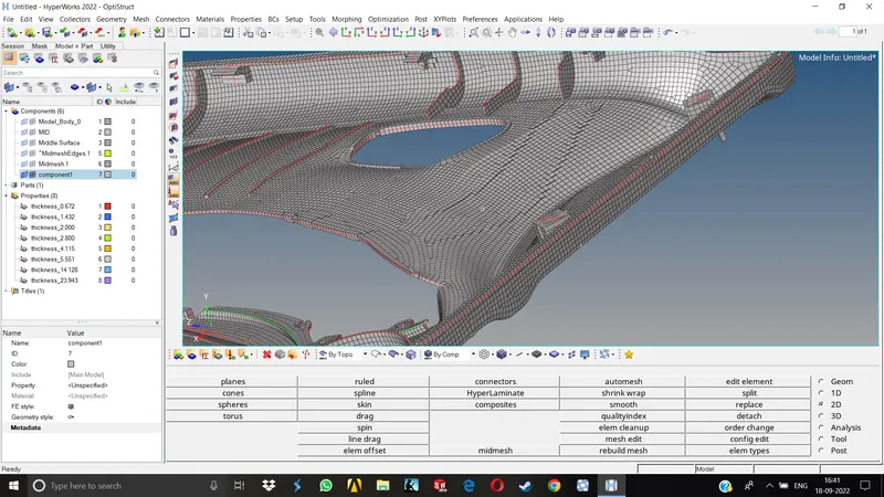
4.As we can see, the results obtained are not very good, instead of trying to improve these results as there are a lot of incorrect thickness capturing has occured, we will proceed with manual thickness assignment.
Manual Thickness Assignment-
1.As we can observe in this model, all the features have varying thicknesses. We can group them together by calculating the average thickness.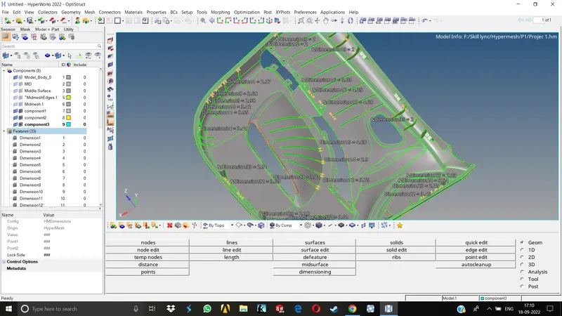
2.After measuring the thickness of all the features & calculating a average thickness for all, we can create new properties & components accordingly.
3.Once we have created the components, we can organize the elements as well as the surfaces to resp. components and assign resp. properties that we have created for each thickness.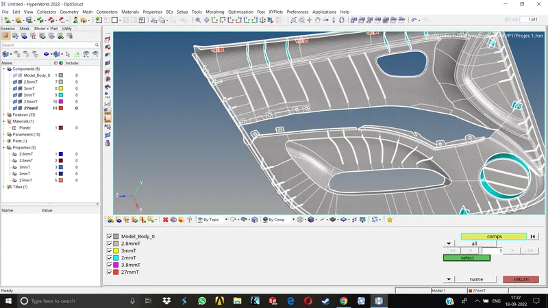
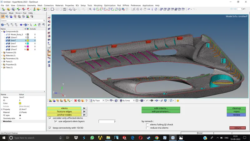
4.Finally we can turn on the 2D detailed element representation to visually see the thickness assignment & Reorder the components & Properties.
Results-
In this project, we have learnt to use all the necessary commands and tools in the hypermesh more efficiently, and we have completed the project step by step in which we first generated the midsurface manually, Then prepared that surface for meshing, then meshing the midsurface both by batchmesh and manual method. We kept the results obtained by manual method as they are more superior. We made sure all the elements are passing the provided quality criteria & tried to kept the tria concentration as low as possible.Finally we assigned proper thickness to the mesh.
Final Model Images-