Week 12:Project-1-Meshing of Door Inner Panel Challenge
AIM - To Mesh the door inner panel which is a plastic component.
OBJECTIVE:
- To Extract a good midsurface for the given inner door panel plastic component.
- To capture the features properly.
- To achieve a good mesh flow with less Tria percentage.
- To assign thicknes to 2D shell elements according to the thickness of the component.
CAD IMAGES OF THE GIVEN COMPONENT:
The below images shows the cad model of the given inner door panel plastic component.
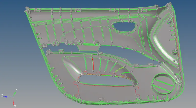
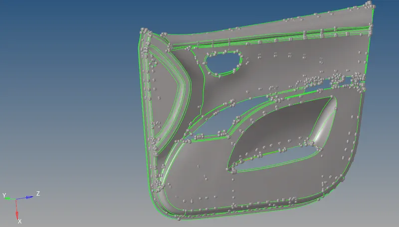
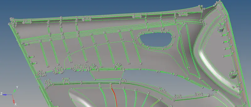
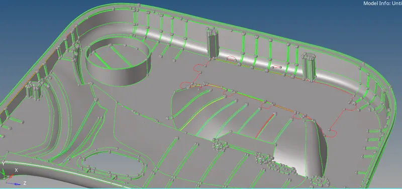
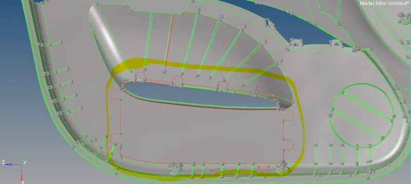
- The above image shows yellow higlighted region which basically shows that there is is surface missing on the component. So to get the midsurface of the component. 'A' surface of the other side has to be used rather than investing time to repair the surface. so that we can save our time.
PROCEDURE:
- No geometrical clean up was done on the give cad model first. Midsurface was extracted manually by using geom → Surface edit → offset command. Geometrical cleanup was done as per requirement of the manual midsurface that too like toggling few lines.
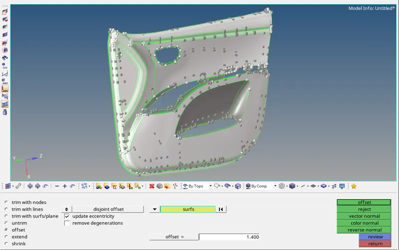
- First the whole surface except the features and surface boundry was selected and offset to get 'A' surface midsurface. The thickness of the whole 'A' surface is around 2.8 mm so, the surface was offset to distance 1.4 mm. Below is the image for the same. The command use geom → surface edit → offset.
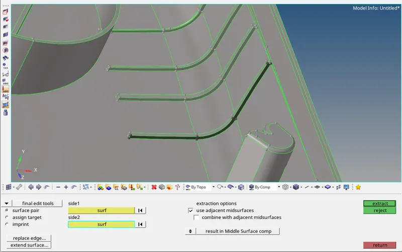
- The manual midsurface was done for Ribs using the same process as above but befor that Ribs were defeatured. The other method use to get the midsurface for the Ribs was geom → midsurface → final edit tools → select side 1 and 2 one by one and click extract. The method is helful in saving time. Below is the image for the same.
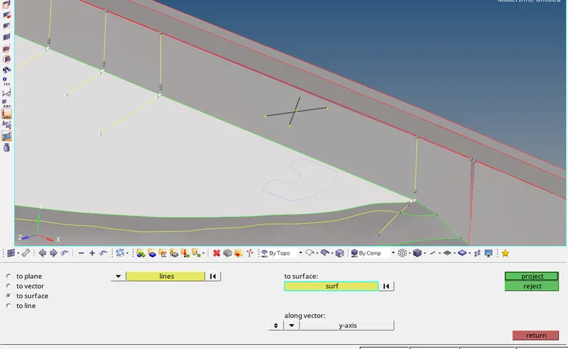
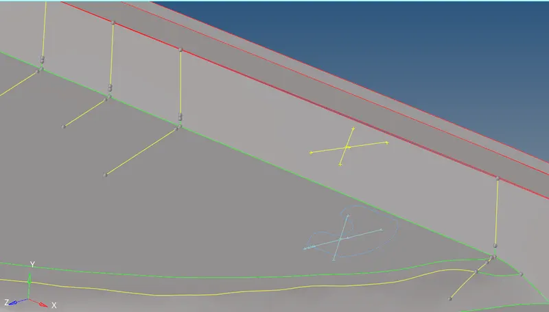
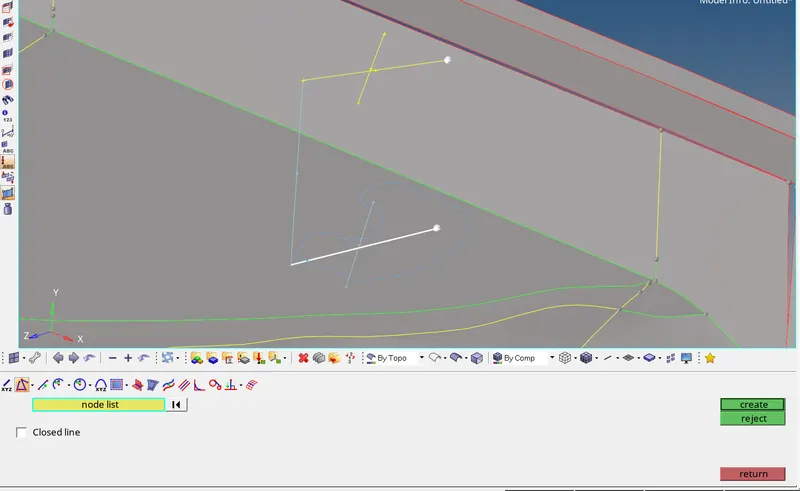
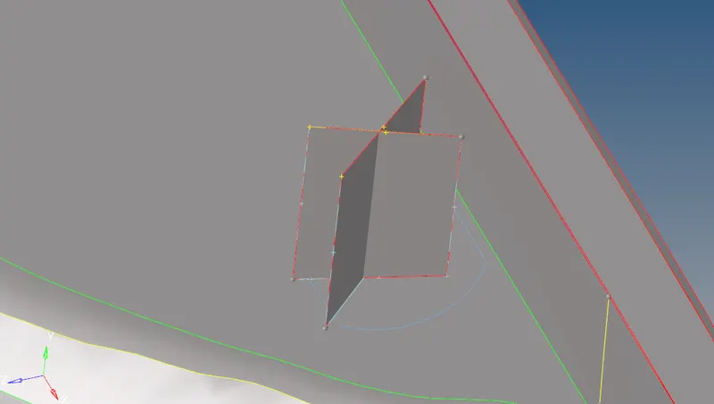
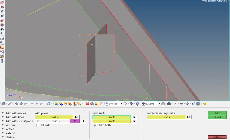
- For the Dog House to intersecting plane were created by projecting line on the surface and then finally extending it. First two itersecting lines were created on the top of the dog house and they were projected to the 'A' Surface using command Tool → project → select lines from the drop down → Then select axis along which the projection is needed → click project. After projection the lines were joined by creating more lines around it to make it like a rectangular frame command used geom → lines → node list → create. After creating lines surface was created using command geom → surface → ruled → create. After creating the surfaces the intersecting surface was trimmed so that actually intersect command used geom → surface edit → trim with surfs/plan → with surfs → trim. After trimming the surfaces were extended to the base surface so that there is proper surface connection command used geom → surface edit → extend → lines to extend → surface to target → click extend. The above steps will create two intersecting surface denoting Dog House feature. Below are the images of the above procedure.
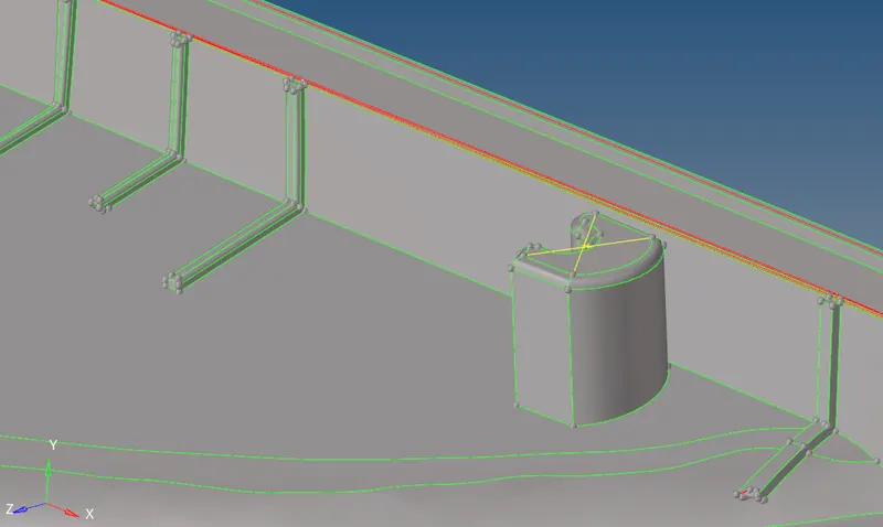
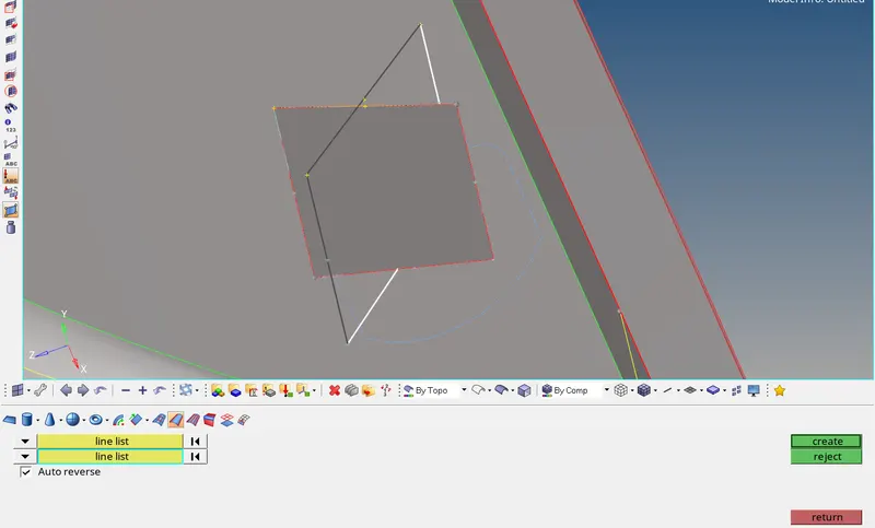
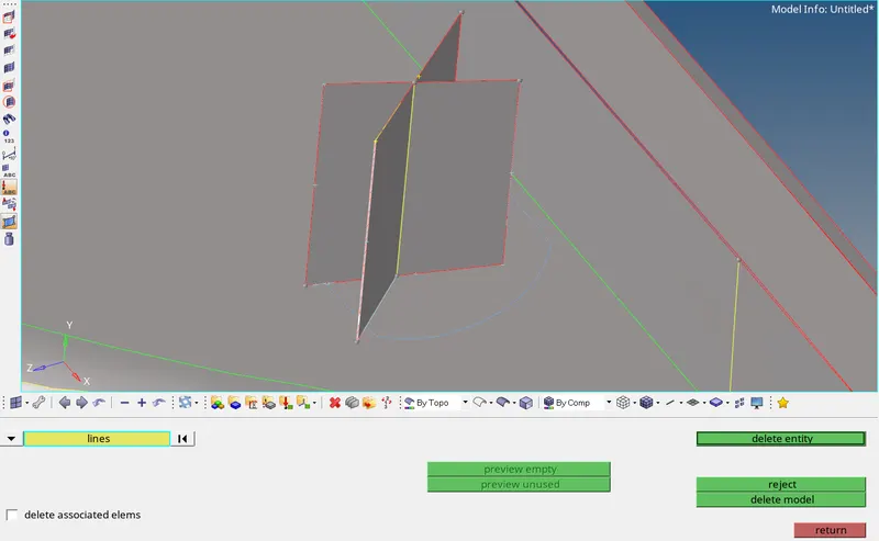
- In the above image the lines that were created need to be deleted before extending the surface to base surface.
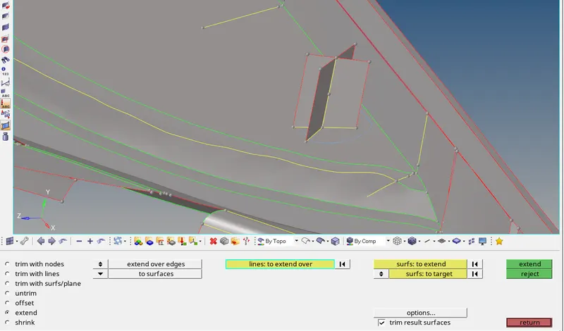
- Using the above steps the whole midsurface was created. Below are the images for the whole midsurface of the inner door panel.
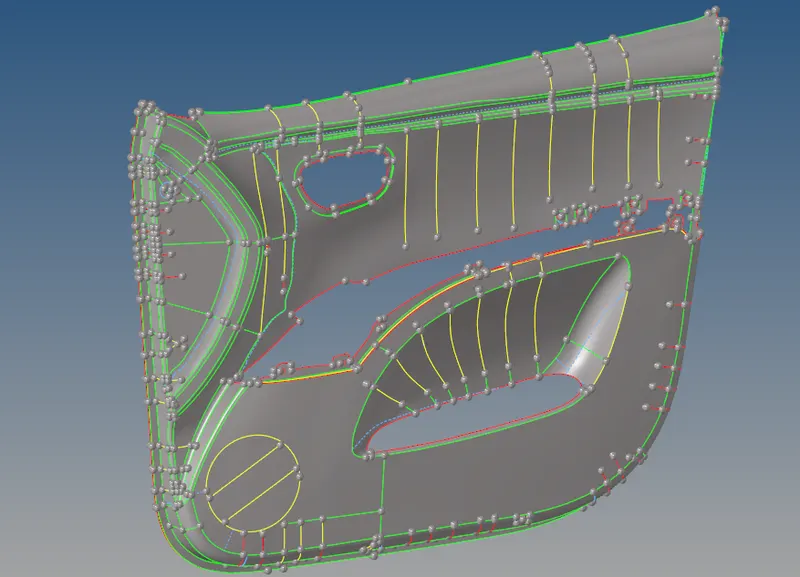
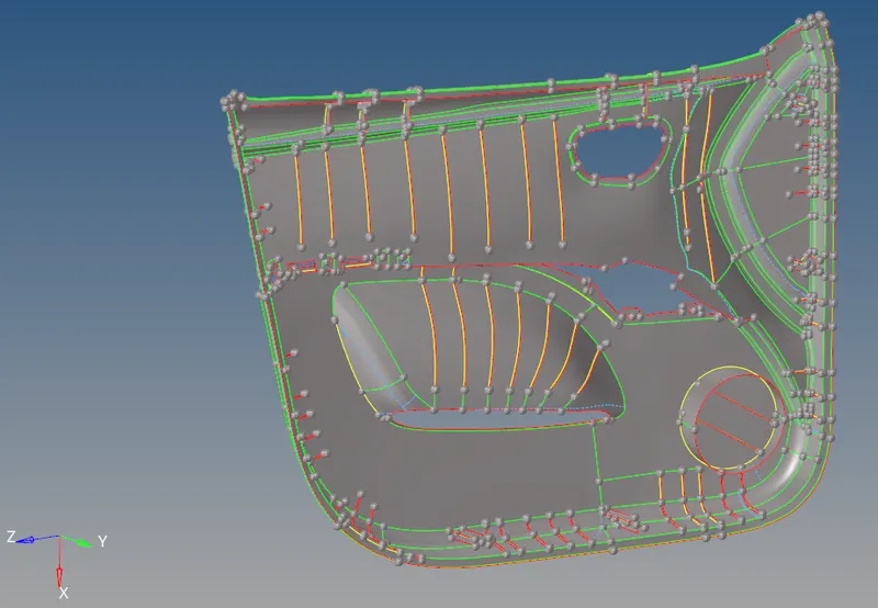
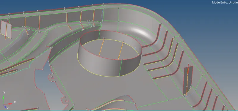
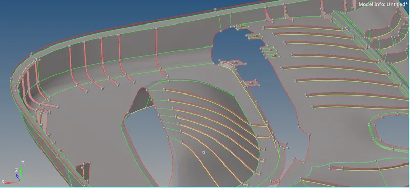
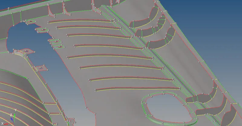
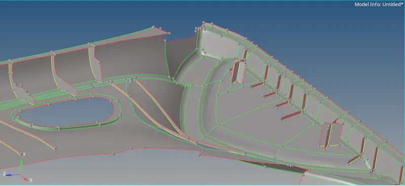
- After completing the manual midsurfacing meshing was done and before meshing criteria file setting was done according to given criteria which is shown in below table.
| S.N | QUALITY CRITERIA | VALUE |
| 1 | Target Element Length | 4 Units |
| 2 | Aspect Ratio | 5 |
| 3 | Skewness | 45 |
| 4 | Warping | 15 |
| 5 | Taper | 0.5 |
| 6 | Min.Length | 2 |
| 7 | Max.Length | 6 |
| 8 | Mini Angle Quads | 45 |
| 9 | Max Angle Quads | 135 |
| 10 | Min Angle Tria | 20 |
| 11 | Max Angle Tria | 120 |
| 12 | Tria % | 10 |
- After setting the criteria file meshing was done. The whole surface was not meshed at once instead portion by portion the meshing was done to achieve good mesh flow and low tria concentration.
- After completing the meshing and achieving good mesh flow thickness was assigned. Since the component have variable thickness so elements that cover different thickness surface was shifted to different component collector and thickness was assigned to by creating coressponding property for it.
- Below are the images for meshing and thickness collector components.
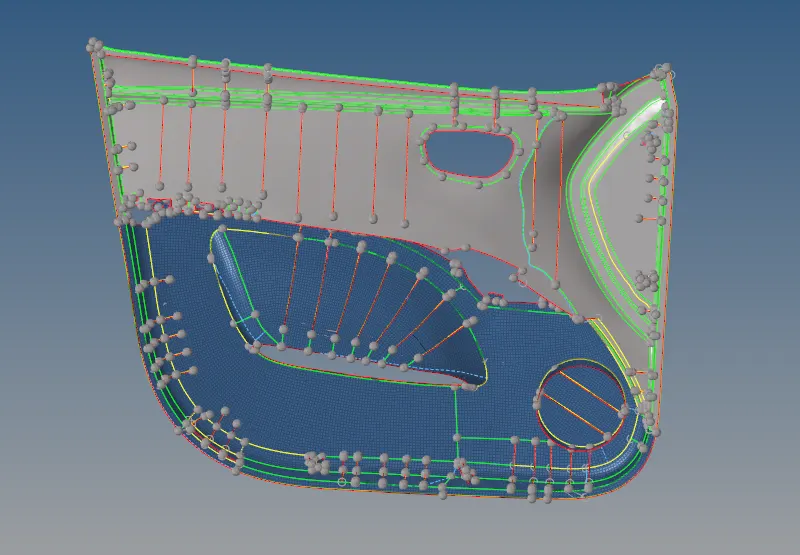
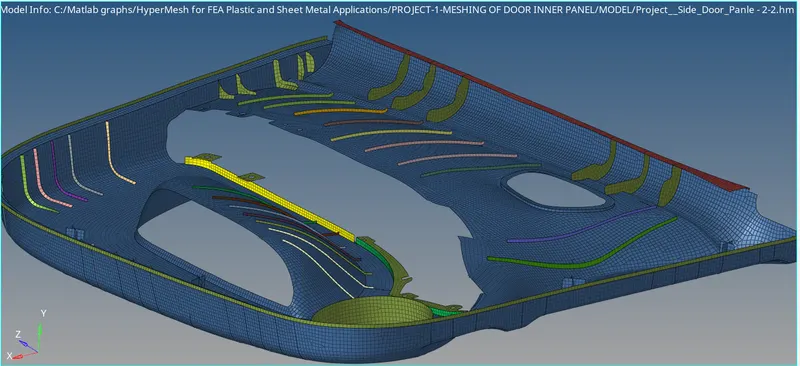
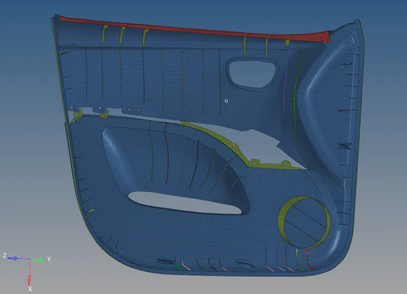
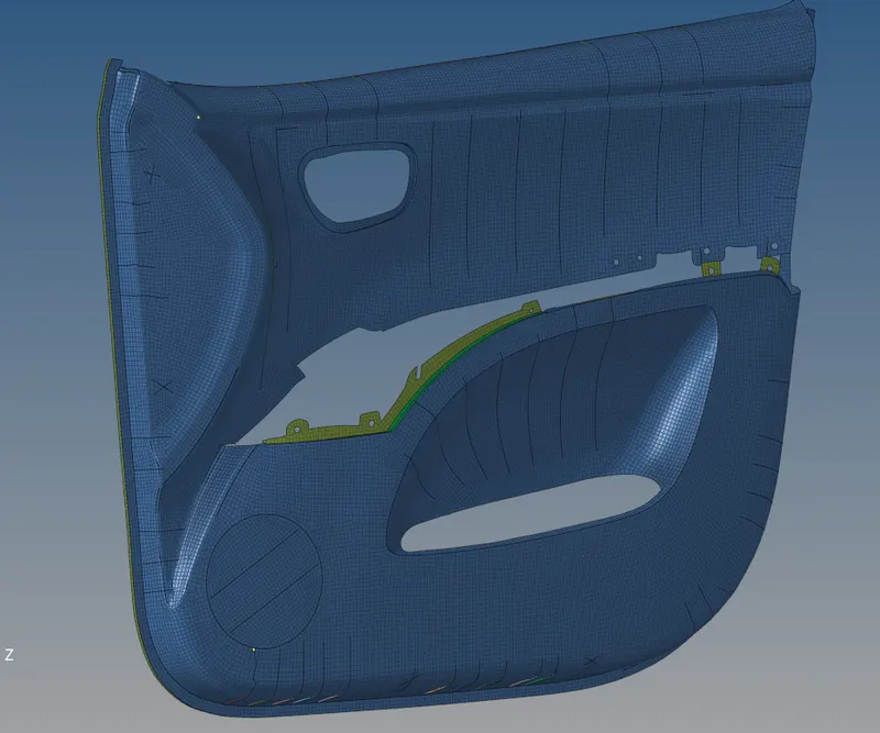
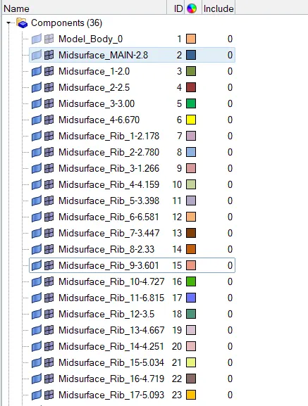
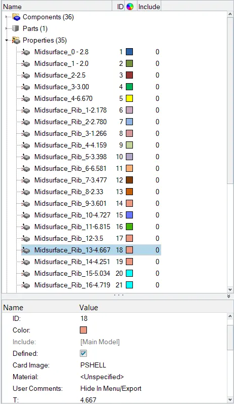
- The images shows the thickness collector. The elements were sorted according thickness of the surface and moved to different component collector.
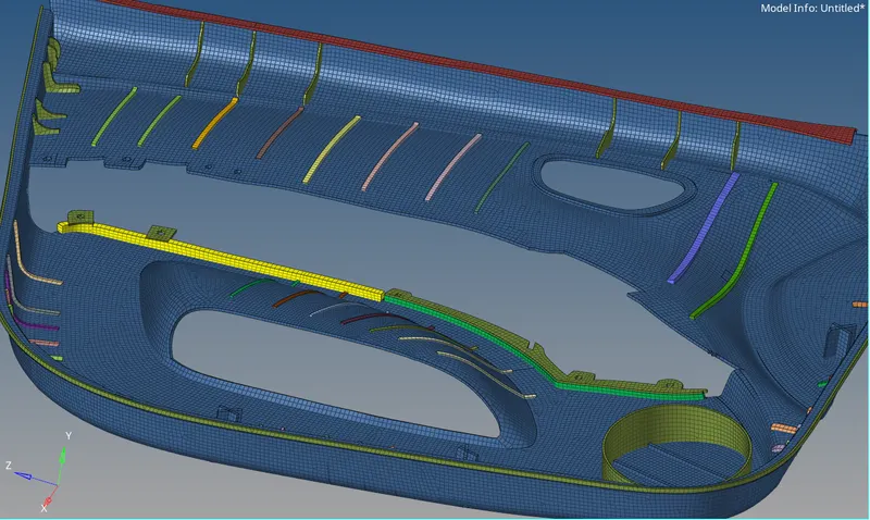
- The above image shows 2D detail element representation mode where the elements have surface thickness to represent the inner door panel in 3D form.
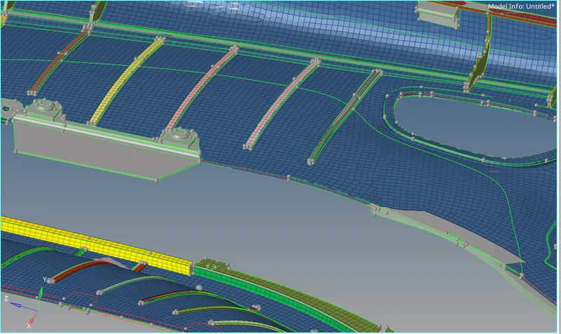
- The above image shows how well the varaible thickness has been captured. The component surfac is turned on and the 2D detail element representation is turned on to compare the thickness of element with component.
- Few checks were perform after completing the meshing they were 1) Normals - It was adjusted, 2) Penetration - no penetration found, 3) Dependency - zero nodes with dependency.
RESULTS:
- A good manual midsurface was extracted for the given Inner Door Panel.
- A good mesh flow with low tria concentration was achieved.
- Thickness was assigned to the component manually by shifting elements to different component collector