Week 12:Project-1-Meshing of Door Inner Panel Challenge
objective :
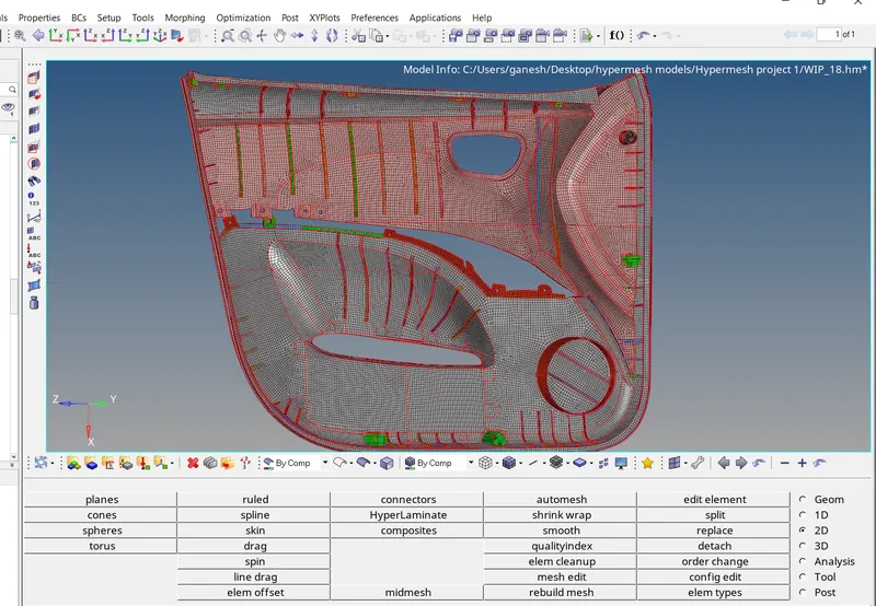
- Meshing of the Inner panel of Side Door CAD Model with Target element Size of 4 units and with proper mesh flow and with tria concentration as well .
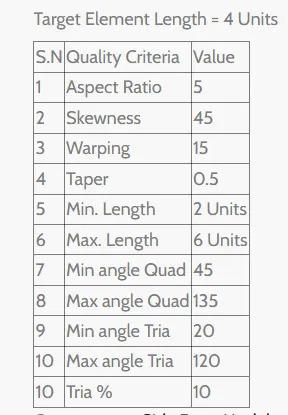
- The Meshed Model should pass all the quality Criteria provided .
- Assigning the proper Thickness to the meshing .
Quality Criteria :
CAD Model of inner panel of the side door :
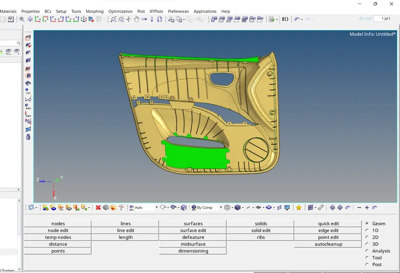
Procedure :
- Initially Cad Model is imported and some Manual Geometrical clean up done .
- Using Surface Tool and the Quick Edits Tool from Geom Tool , geometrical cleanup is done .
- Whole Inner panel of side door is then devided into the 4 pieces and kept them in diierent collector for better meshing convineance .
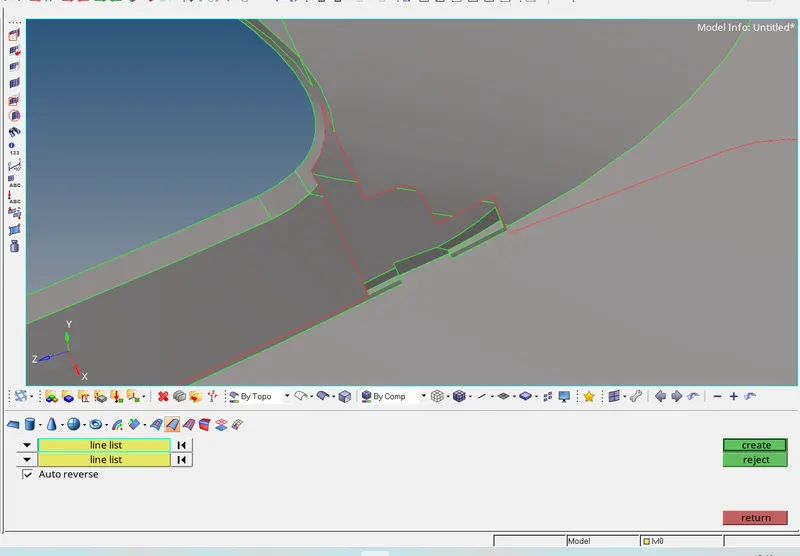
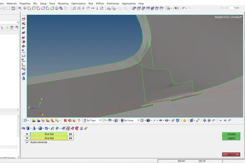
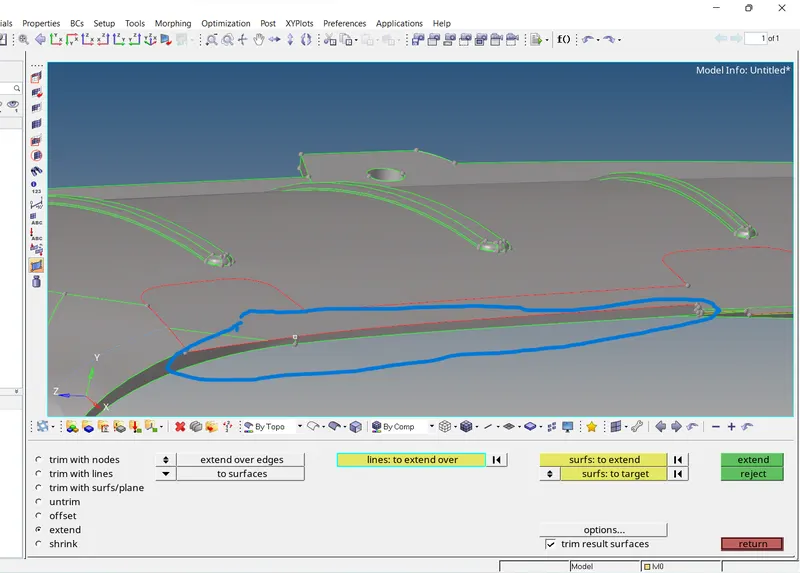
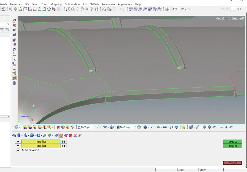
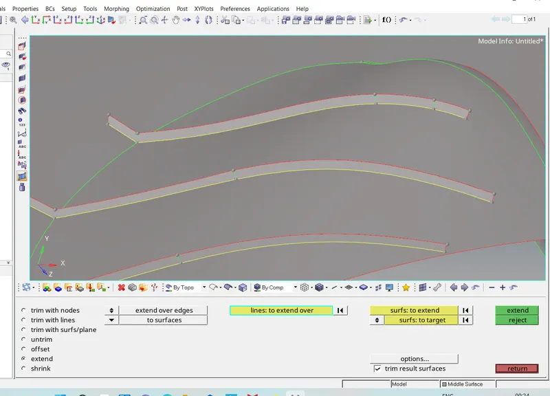
- In below image , marked surface height too short to make surface for geometry clean up ,using the Geom - Surface edit - Extend Tool , surface is extended and then using the Geom - surfaces - Ruled Tool surface is created which can be seen below .
- Using the Geom - Defeature Tool , The Side Door inner panel is the Defeatured For the surfaces where mesh will fail for trhe minimum length element.
- The surfaces which are hypermesh fail to defeature are defeatured manually .
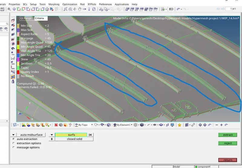
- Then for all the 4 peices of the side door inner panel , the Midsurfaces are extracted using the Geom - Midsurface Tool as .
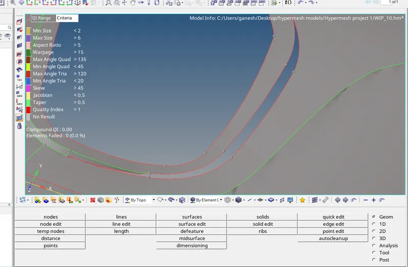
- Now here also the hypermesh is missed to extract midsurfaces of the some surfaces can be seen below .
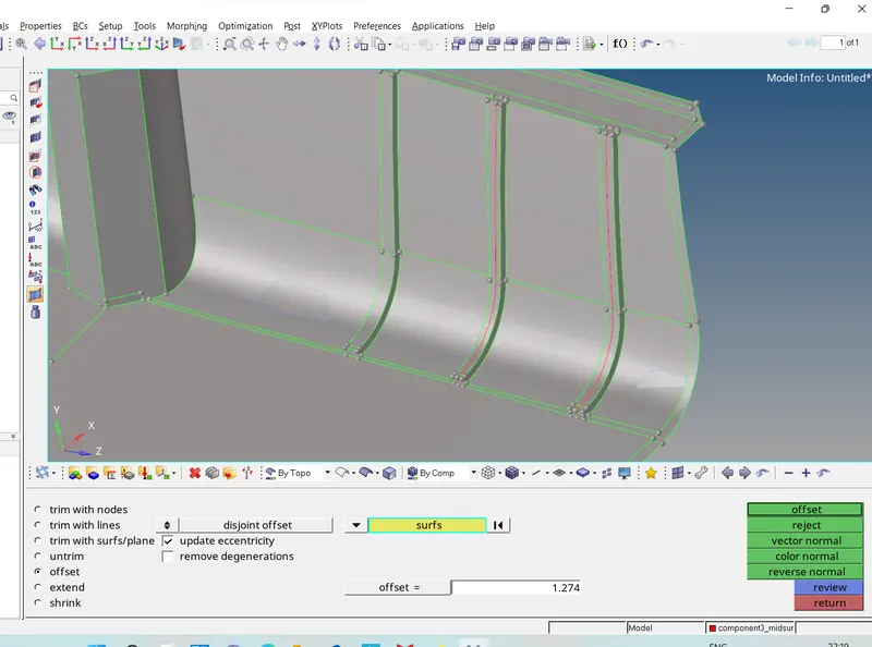
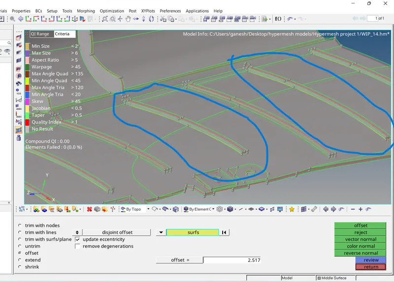
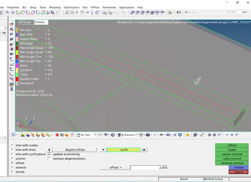
- This missed surfaces are Extracted manually using the Geom - Surface Edits - Offset Tool as ,
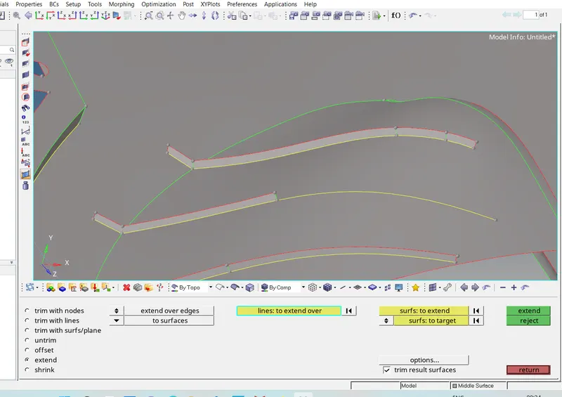
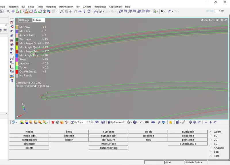
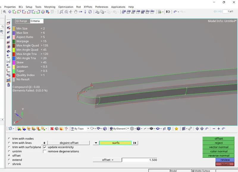
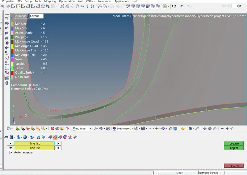
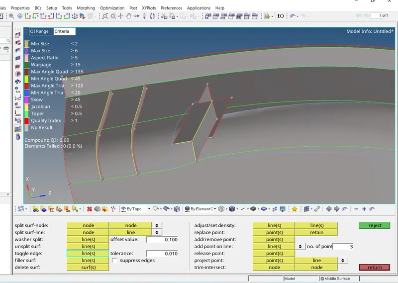
- Here in below image . missed midsurface is Created toggling lines using the Quick Edits - toggle edges and the surface is generated using the Ruled - surfaces - geom Tool .
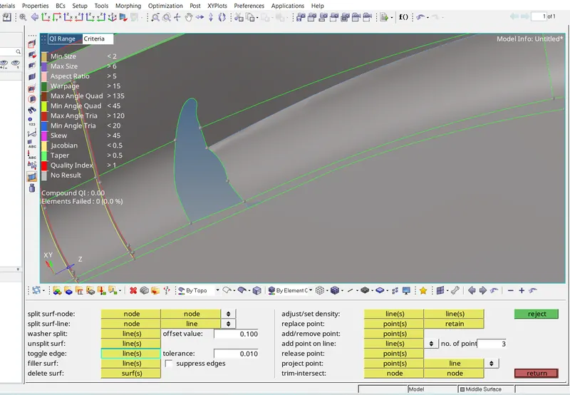
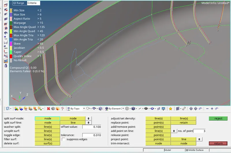
- For Some surface the midsurfaces were not prperly created , which are also created manually using the geom - Surface Edits - Offset Tool as ,
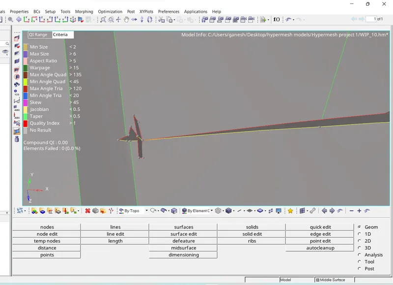
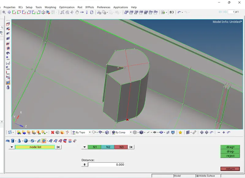
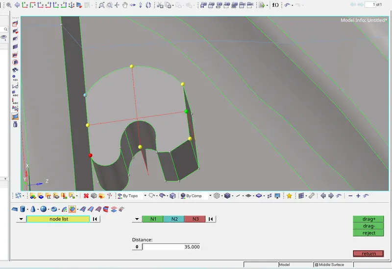
- The Area which haviung the more than 6mm thickness are captured draging the surface with the help of Node using the Geom - Surfaces - Drag Tool as ,
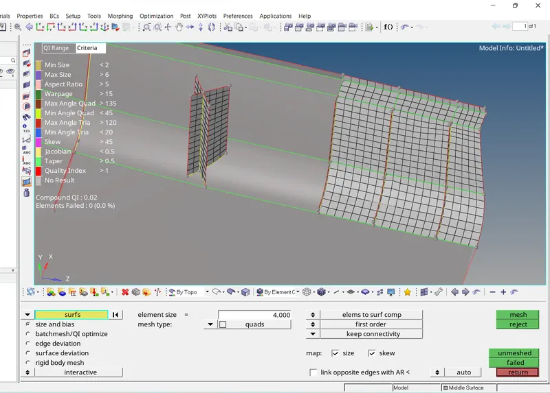
- Now Meshing of the Side door inner panel is done step by step to get proper meshing and the proper mesh flow as well .
- Initially the Quality criteria setting is done and view is converted into the By element Quality , so that we know which elements are failing every time we mesh the surface .
- After meshing Every time we need to Preview Equivalence for every element to have proper connectivity between elements using the Tool - Edges - Element Tool the equivalnce can be checked .
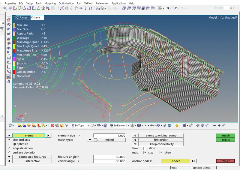
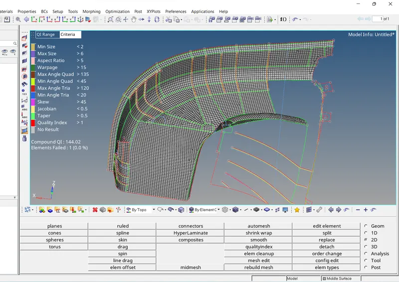
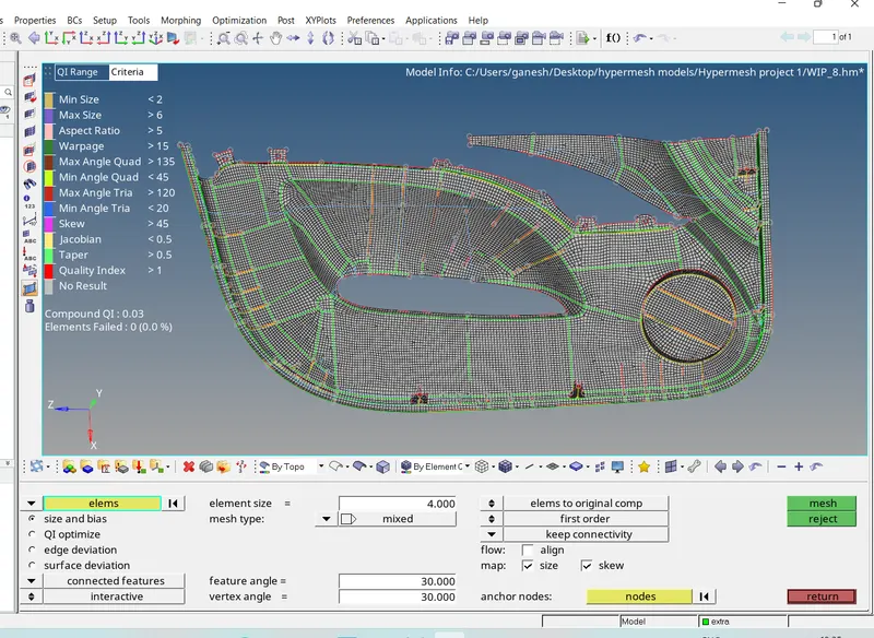
- Surfaces with improper attachements are tackled as follows .
- Firstly surfaces with not proper attachments are deleted and then created the surfaces with hole as seen below .
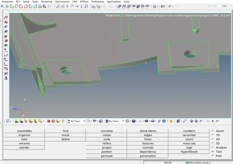
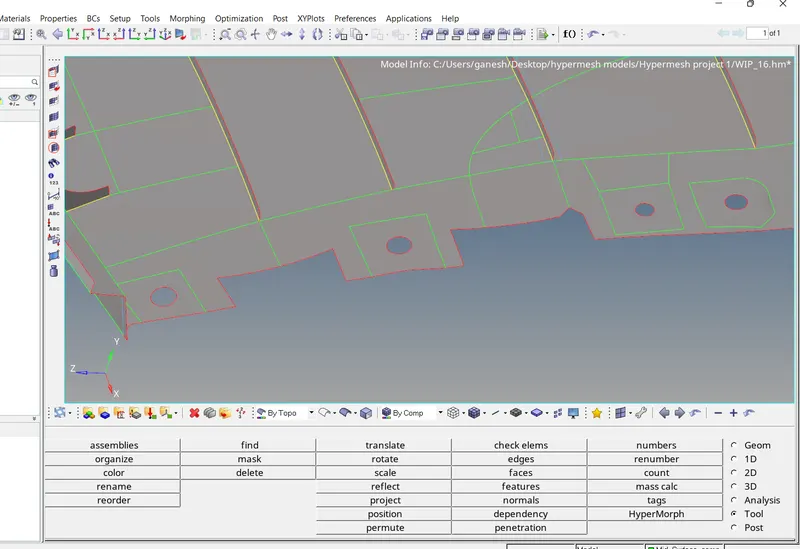
- After all meshing the whole component , I have assigned the midmesh thickness using the Mesh - Assign - Midmesh Thickness Tool .
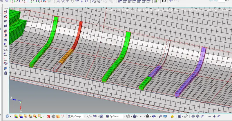
Results:
- Final meshed surfaces can be seen below .
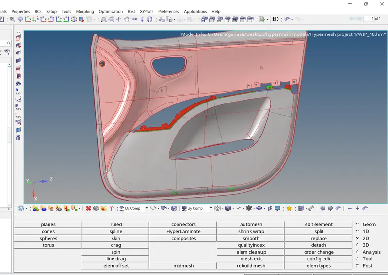
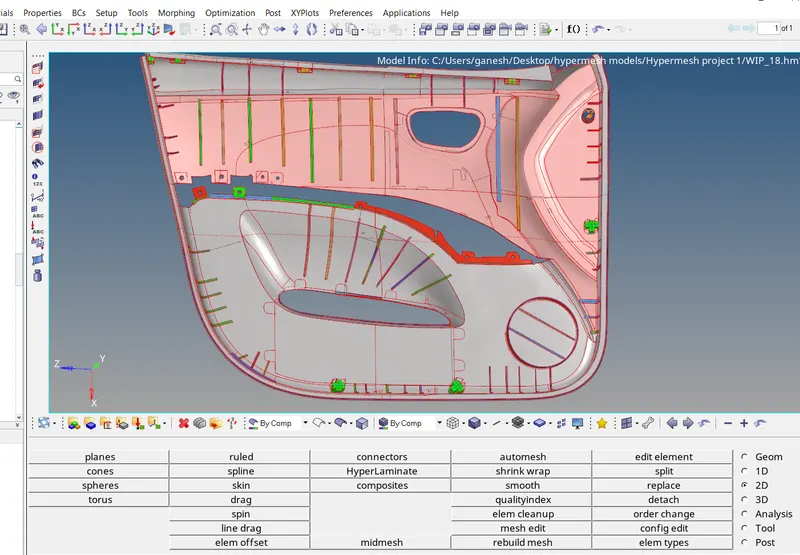
Front side : Back side :
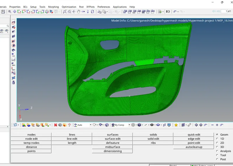
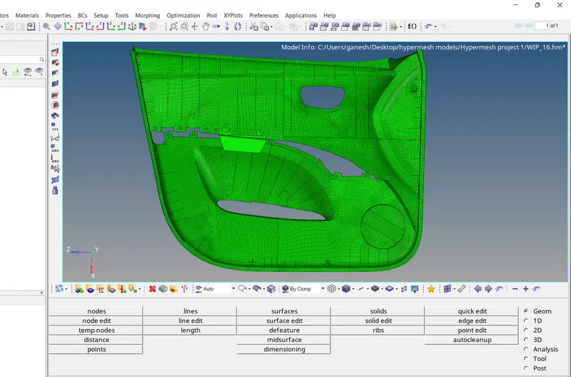
With Shaded Elements and the feature lines .
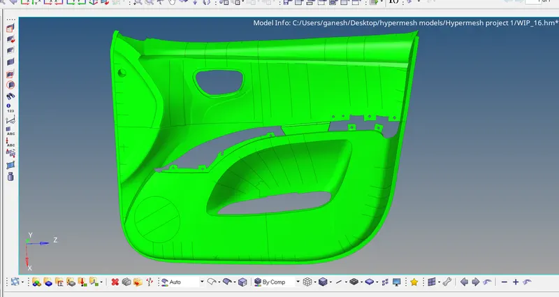
- Model after Thickness assignment .
- Final Hypermesh Model file is attached below .