Week 12:Project-1-Meshing of Door Inner Panel Challenge
AIM: To mesh the given Side door model component with given element quality criteria.
Given side door model has only one component.
Objective 1: To extract the mid-surface of side door with manual mid-surface method.
Step 1: Import the given component and cleanup the geomtery without any irregular free edges.
Step 2: Extract mid-surface manually by Offset method. For manual mid-surface, measure the distance between inner and outer panel surfaces.
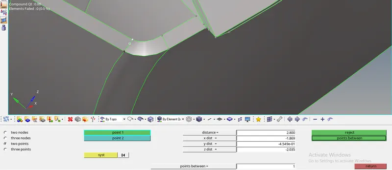
Step 3: select the surface which has to be offset, and input the offset value which is half the measured inner and outer panel surfaces.
Step 4: Check vector normal and change the vector normal in which direction surface has to be offset and click on offset.

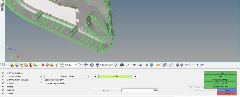
Step 5: Clean up geometry in offsetted mid-surface also for better flow of mesh where ever required by toggling edges and removing unnecessary points.
Objective 2: Creating mid-surface for ribs present in component.
Step 1: For creating mid-surface for ribs go to lines and select midline feature in Geometry>lines>Midlines.
Step 2: Select the lines(Line lists) of both ends in ribs where mid line has to be created, and click create.
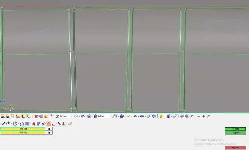
Step 3: Now that the line is created, create a surface from that line to mid-surface plane by trim with line feature.
Step 4: For trimming surface go to Geometry>Surface edit>trim with lines. Now select the midlines and mid-surfaces where surfaces of ribs has to be created and trim. Keep to normal to surface in creating options of surface.

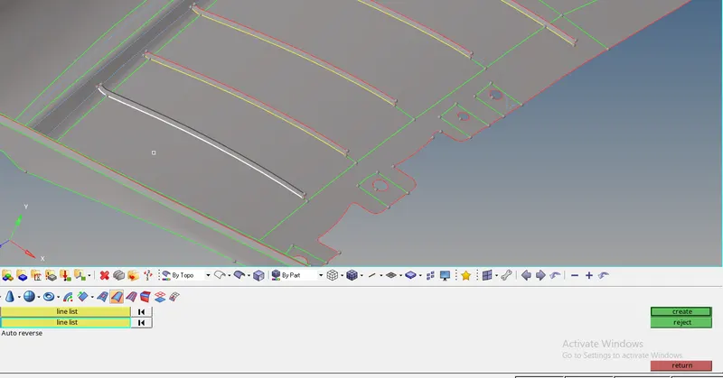
Step 5: For creating surface of midlines go to Geometry>Surface>Ruled surface option. Now select lines(By two line list) and click on create.
Objective 3: Meshing the component by given element quality criteria.
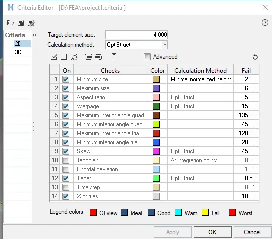
Step 1: Before creating the mesh set the element quality criteria by going to prefernces>criteria file settings>edit the parameters as given criteria and save criteria file.
Step 2: Select mid-surface of component to be meshed and go to 2D panel.
Step 3: For better meshing create partitions(Splitting) for the extracted mid-surfaces.
Step 4: For generating the mesh go to 2D>Auto mesh>set target element size as 4 and type of mesh as mixed>click on 'mesh'. for better mesh flow quality it is suggested to mesh with maximum of 3 to 5 surfaces at a time, which are adjacent to each surfaces.
Step 5: For the failed elements with min,max,aspect ratio,warpage,min &max angle quad,trias it is recommended to inspect each element with clean up tools available in 2D>Quality index>clean up tools, where element optimization,drag tria elements,combine or split elements can be done to reduce number of failed elements.
Step 6: In order to develop the fine meshing, remesh the required elements by selecting seperately in regular sizes(Squares, Rectangles).
Step 7: Smooting of elements can be done where the density of elements is high by going 2D panel>smooth>and select elements>click on smooth.
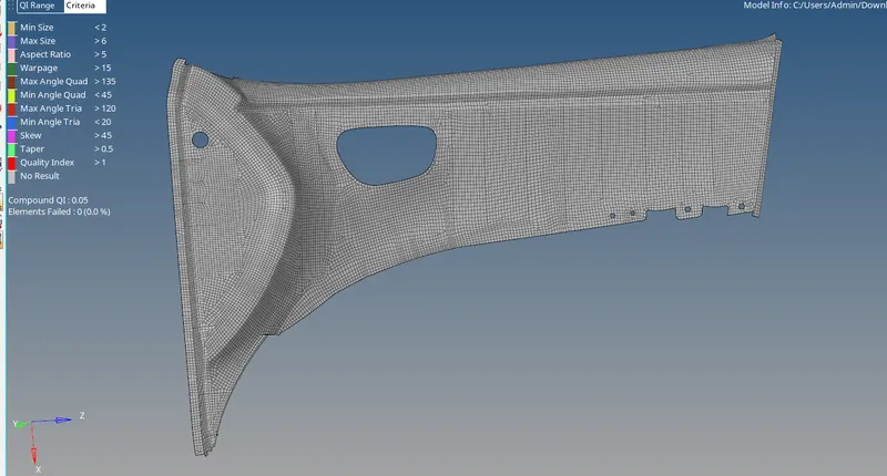
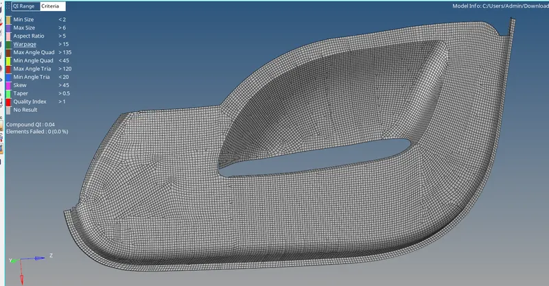
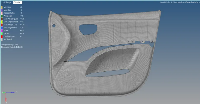
Images after meshing of component
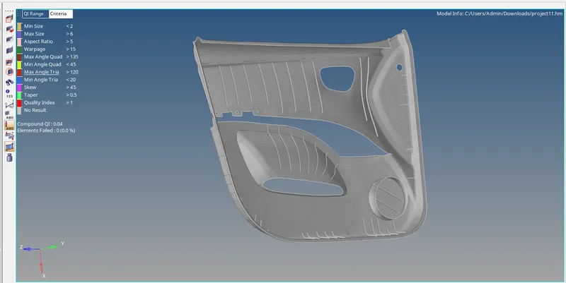
Objective 3: To find free edges between meshed elements for connectivity.
Step 1: For finding of free edges press shift+f3 buttons and select component and click on 'Find edges' .
Step 2: If the free edges are present press f3 and replace the nodes with nearest nodes where connectivity has to be done.
Step 3: delete the free edge in left panel and try again if any free edges are present.
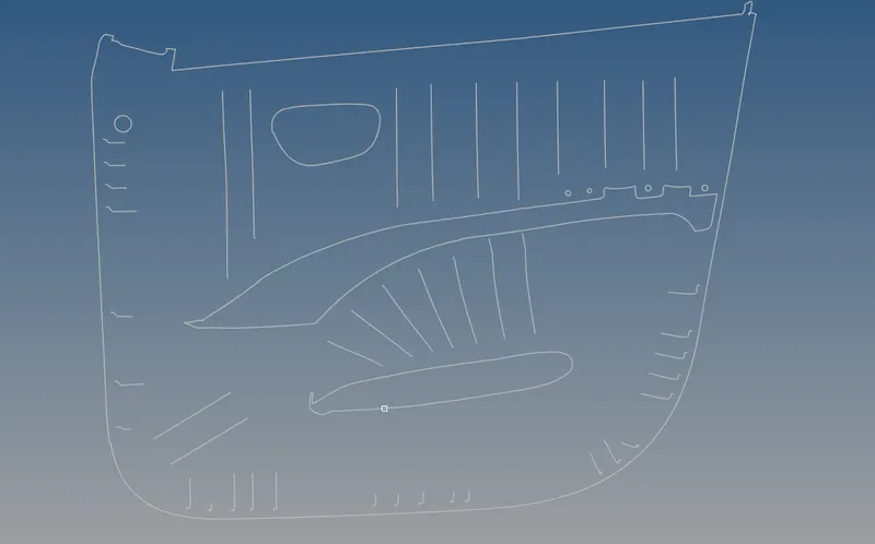
CONCLUSION: Thus the given side door plastic model has been meshed with the given element quality criteria.