Week 12:Project-1-Meshing of Door Inner Panel Challenge
Side Door
Aim
To mesh the given side door model according to the given criteria
Procedure
- Before we can mesh the model, it is necessary to prepare the mid surface of the given model
- As this is a model with several surfaces having a varying thickness, we will need to manually extract the mid surface for several components
- First, we can extract the base of the model which has a constant thickness using manual offset in surface edit and using by face option
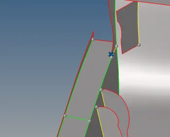
Figure 1
- In this portion before we can extract the rib,it is necessary to properly join the surfaces as they may not be properly attached
- To do this, we can use the line drag option to make the surfaces collinear and then extend the surfaces and trimming out the excess parts.

Figure 2
- The vector for line drag must be chosen carefully along the surface.
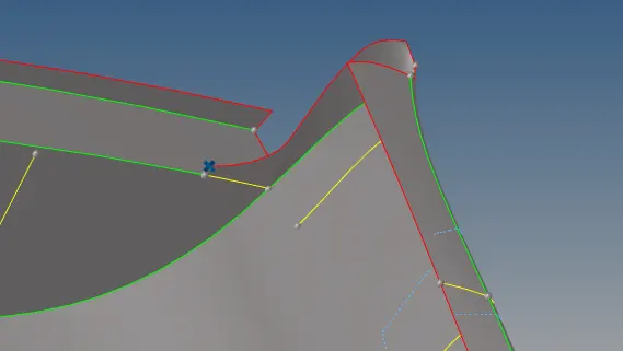
Figure 3
- After that, we can extract the rib and connect it to the surface appropriately
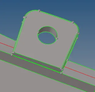
Figure 4
- Features such as the one above cannot be captured properly as such , so instead, it is better to at least capture the hole instead as shown
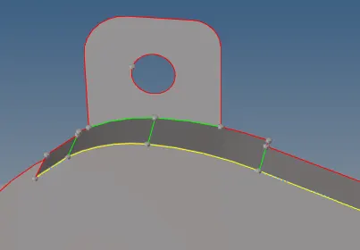
Figure 5
- The resulting manifold edges are unavoidable
- For generating the mid surface of the ribs, there are several methods available to us
- If the rib thickness is constant, we can simply offset it and extend it appropriately.
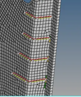
Figure 6
- If the rib has a varying thickness, the best option is to simply create a midline and then project the line to the base using the surface trim option and then create a new surface.
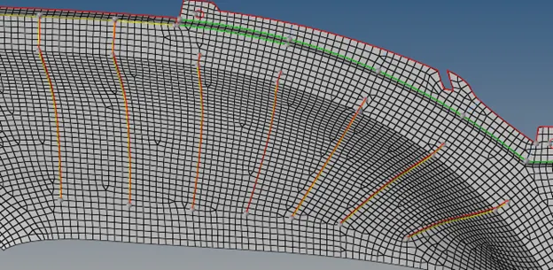
Figure 7
- For thickness assignment, we use the auto review thickness command as shown and use the average thickness.
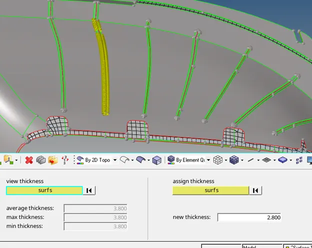
Figure 8
- Mesh Criteria is given in table 1
|
S.N |
Quality Criteria |
Value |
|
1 |
Aspect Ratio |
5 |
|
2 |
Skewness |
45 |
|
3 |
Warping |
15 |
|
4 |
Taper |
0.5 |
|
5 |
Min. Length |
2 Units |
|
6 |
Max. Length |
6 Units |
|
7 |
Min angle Quad |
45 |
|
8 |
Max angle Quad |
135 |
|
9 |
Min angle Tria |
20 |
|
10 |
Max angle Tria |
120 |
|
10 |
Tria % |
10 |
- For meshing, it is best to mesh surface by surface and remesh/solve off elements appropriately.
- While splitting the surface into smaller surfaces for a better mesh, doing this on large components drastically increases the time taken to complete meshing.
- Opposite trias can be solved by dragging them and combining the elements using the Quality index commands.
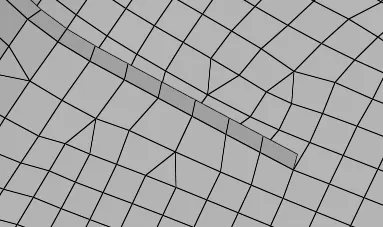
Figure 9
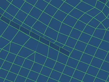
Figure 10
- It is important to check for connectivity using the check elements option and visually checking each edge and solving them appropriately using the connect nodes option and equivalence option.
- It can be observed that hypermesh is not recognizing the hole below.
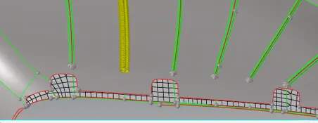
Figure 11
- To solve this,go to parameter file settings and delete the remove hole row in holes 2d and 3D.
- After this,you can delete the elements,project them to the hole and rebuild accordingly.
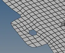
Figure 12
- Using the check edges option to verify the connectivity of the mesh.
- If any are does not have connectivity use the node replace option to solve it.
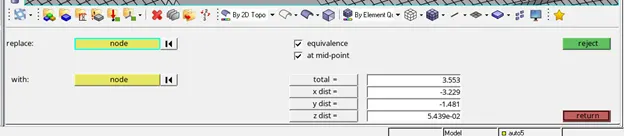
Figure 13
- Setting it to thick 1d elements helps visualize the free edges easier

Figure 14
- In cases of large areas, it can be a tedious process to replace the nodes individually.
- An alternative can be to use the mesh edit option to do the same.
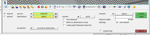
Figure 15
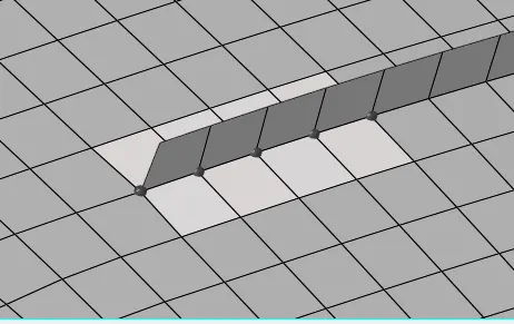
Figure 16
- Another option if the mesh edit command does not work is to delete the elements around the area by creating a cut zone.
- Before this, set hypermesh to keep mesh mode as otherwise you risk ruining mesh flow
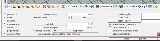
Figure 17
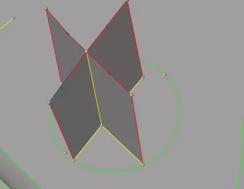
Figure 18
- After creating the surface delete the elements inside and project the outside elements to the boundary created.
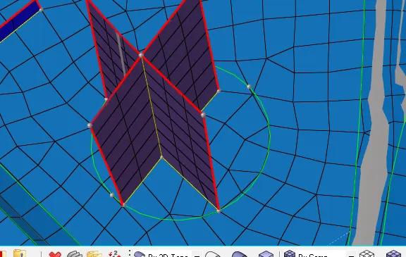
Figure 19
- Set hypermesh back to advanced remesh and remesh the surface
- There should be no connectivity issues after this
- Proceed with the same process for all surfaces.
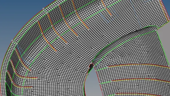
Figure 20
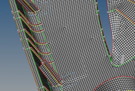
Figure 21
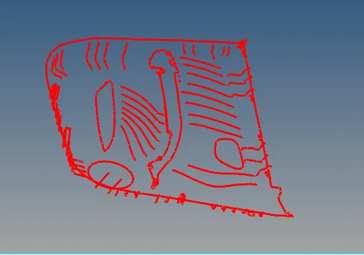
Figure 22
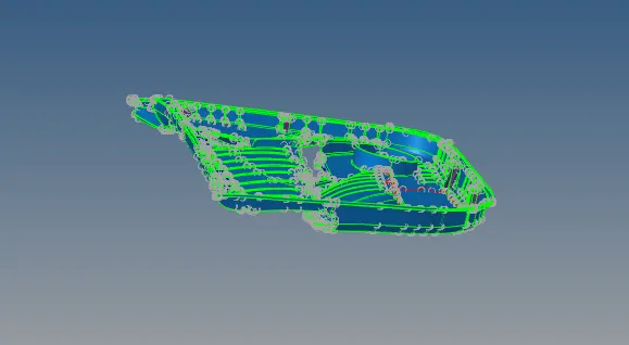
Figure 23
- For automatic mid mesh thickness, go to mesh->assignàmidmesh thickness
- Change solids to surfaces and select the parent geometry.
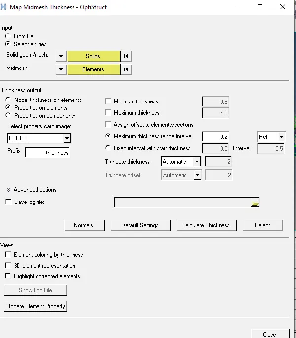
Figure 24
- Select the mid mesh elements.
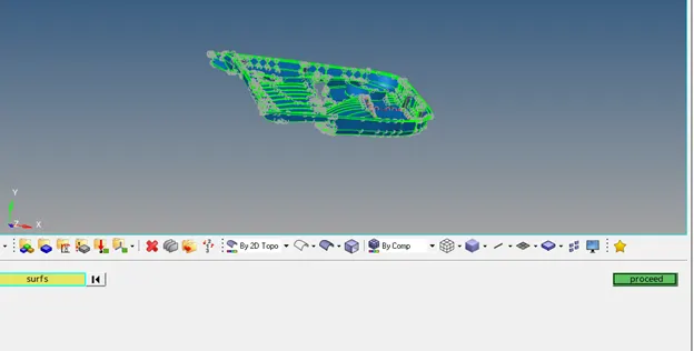
Figure 25
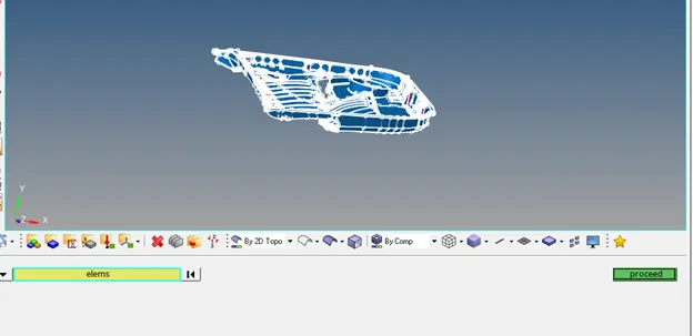
Figure 26
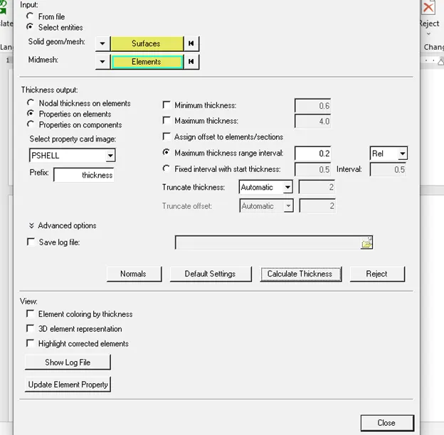
Figure 27
- Select calculate thickness and hyper mesh automatically assigns thickness to the elements.
- Verify the thickness by comparing it with the parent geometry in shadow mode.
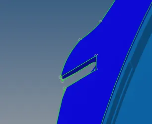
Figure 28
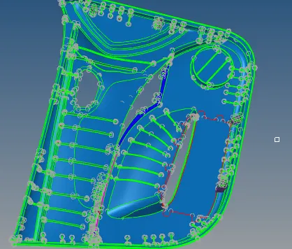
Figure 29
Learning Outcomes
- Automatic thickness assignment
- Using line drag/line ruler options to patch the mid surface
- Create cut zones to fix connectivity of the mesh
- Using mesh edit to solve connectivity
- Updating mesh thickness
Result
The given model has been meshed according to the given criteria.