Project - 1 - [CAR’S SIDE DOOR PLASTIC MODEL]
#PROJECT 1 - CAR’S SIDE DOOR PLASTIC MODEL
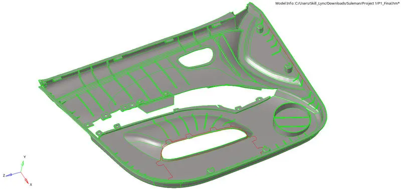
AIM: 2D Mesh on Car’s side door and Assigning Thickness.
ABSTRACT : A car door is a type of door, typically hinged or attached by other mechanisms in front of an opening which is used for entering and exiting a vehicle. These doors can be opened manually, or powered electronically. vehicles today are usually operated by use of a handle which requires the user to pull, lift, or tug. Doors have an inner full-width panel consisting of arm rest, electric windows, central locking system, and speakers. These panels typically consist of a foamed core covered with either textiles or plastics.
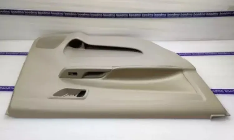
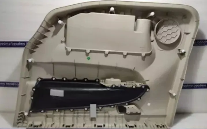
OBJECTIVES : Generating mid surface, geometry clean up, assigning thickness and 2D mesh with following quality criteria -
Target element length 4mm
Minimum element length 2mm
Maximum element length 6mm
Minimum quad angle 45
Maximum quad angle 135
Minimum angle tria 20
Maximum angle tria 120
Tria percentage 10
Aspect ratio 5
Skewness 45
Warping 15
Taper 0.5
PROCEDURE:
STEP 1: Duplicate the parent surface model to another collector to keep the parent surface safe.
STEP 2: Organise the parent surface to another component collector and duplicate the surface and move
*Tool>Organise>surface>set current component>select dest component>Duplicate>move.
STEP 3:
- We can delete the unnecessary solid surfaces which are not required to mesh otherwise it will create bad mesh.
*F2>surface>select surface>delete entity
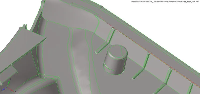
- Fill the void surface
*Geom>quick edit (F11)> filler surface>select boundary line of the circle
- Toggle the line
*Geom>quick edit (F11)> Toggle edge>select boundary line of the circle
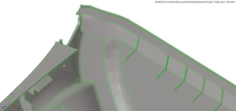
STEP 4: Check the thickness of the component- To get the exact thickness of the sheet we can proceed with the following command.
- Create a node to any one side of the sheet metal
*Geom>temp node>nodes>select surface>press left click to add the node>add
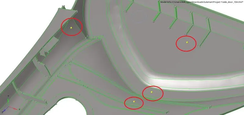
- Project this node to the opposite side of the surface after duplicating the node.
*Tool>project >nodes>select node>duplicate>current component>to surface>Select surface>Project
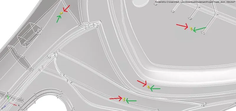
STEP 5: Measuring the distance between two nodes which gives as the actual thickness of the sheet.
*F4 or Geom>distance>two nodes>select both nodes by N1,N2 and we’ll see the distance.
STEP 6: Repeat step 4 and 5 to few more surface to get sure about the thickness at different surface
This measuring thickness will help us to know whether there is any surface which has varying thickness and also help us to assign thickness to 2D elements after generating mesh.
In this case there is varying thickness so we have to proceed for generating midsurface manually.
STEP 7: We can move the surface of the components to another collector so that we can work on the two parts of side door panel separately.
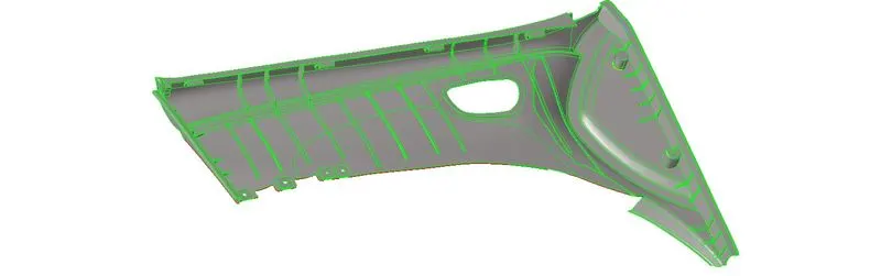
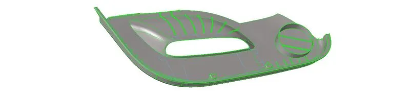


STEP 8: Generating Mid surface of the car’s side door.
- Side door panel consists of varying thickness so we can’t go through the auto midsurface panel.
- We’ve to do it manually by offsetting the surfaces to create a mid surface.
*Geom>surface edit>offset

- Select surface
- Duplicate
- Current component
- Give offset distance (T/2)
- Check normal
- Click offset
We'll see that the mid surface is being created and this will save in the current component collector.
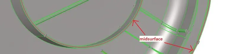
STEP 9: This is how we have to go through all the surfaces one by one of that particular component and create a mid surface by offset command.
- It’s uneasy to create a midsurface of ribs provided in the component by an auto midsurface panel or surface offset panel.
STEP 10: After creating the mid surface of all the components we have to proceed for geometry clean up on the mid surface to get a better mesh result by quick edit panel. We have to toggle the unnecessary lines and remove free edges. We can split surfaces which will help us to mesh the surface properly and adding points to create a split surface by node or line.
*Geom>quick edit or (F11)

STEP 11: To create a mid surface of Ribs we can go through following command.
- Defeature the fillet surface which is less than given element size.
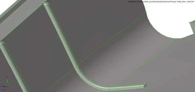
*Geom>defeature>surface fillet>find fillet>select surface>set min and max radius>find>remove
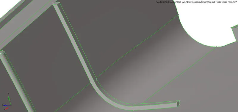
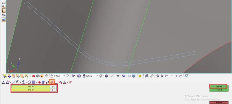
STEP 12: Creating mid line on above and bottom part of rib.
*Geom>lines>midline>select line list 1>select line list 2>create
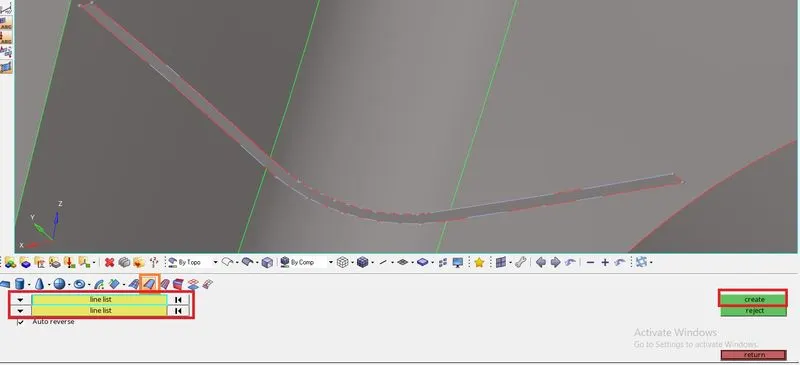
STEP 13: Creating surface
STEP 14: Connecting rib to below component mid surface
- There are different methods to connect rib to component mid surface
(A). Extending surface by surface edit extend panel.
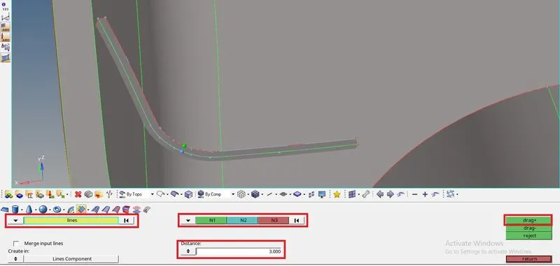
(B). Surface drag along vector panel, trim and deleting unused surface.
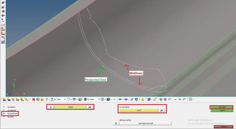
(C). Projecting line to component surface and follow any one of above command (A) or (B).
_________________________________________________________________________________
(A). Extending surface by surface edit extend panel.
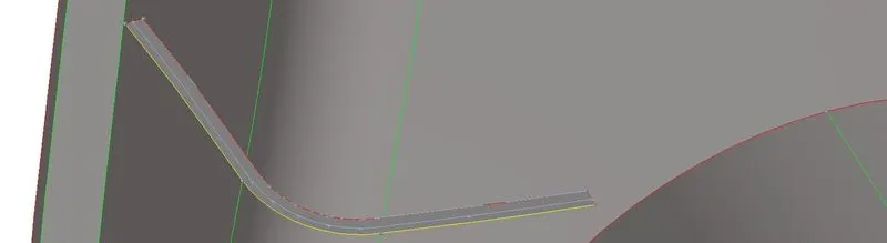
(B). Surface drag along vector panel, trim and deleting unused surface.
- Surface drag
- Trim and deleting surface.
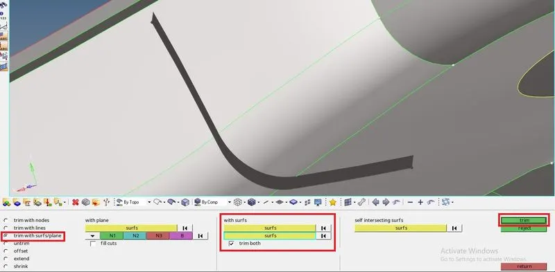
- Rib connected to component surface.
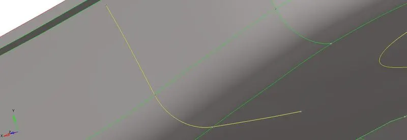
(C). Projecting line to component surface and follow any one of above command (A) or (B).
- Generating the midline of the component and projecting it to below surface.
- Creating surface
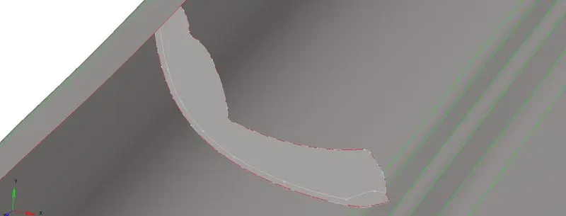
- Following (A) command to connect to below surface.
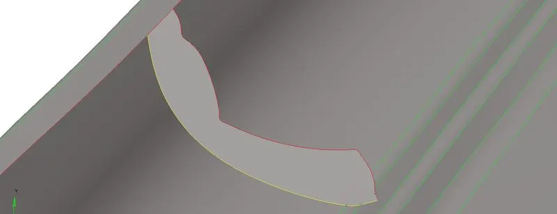
STEP 15: After cleaning up the geometry and creating mid surface, we can now proceed for 2D mesh on the surfaces one by one.
*2D>automesh>surface>select surface>set element size(4mm)>set element type(Mixed)>mesh
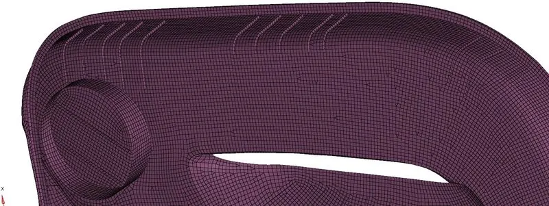
STEP 16: After completing the mesh on each mid surface check and remesh few elements to avoid trias elements as possible to get proper mesh flow.
STEP 17: Check for the failed elements which violets given quality parameters by setting up criteria file setting as per given data.
*Menu Bar>preferences>Criteria file setting
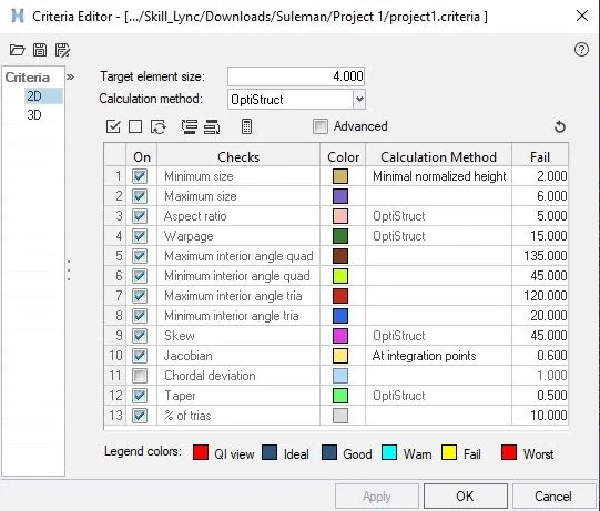
We have to mind the given quality criteria, we can check elements by following command-
*Toolbar>element colour mode>by element quality
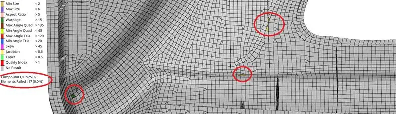
STEP 18: Correct the failed elements by Quality Index Panel and 2D remesh Panel.

STEP 19: Meshed elements should capture the given feature surface by Project panel.
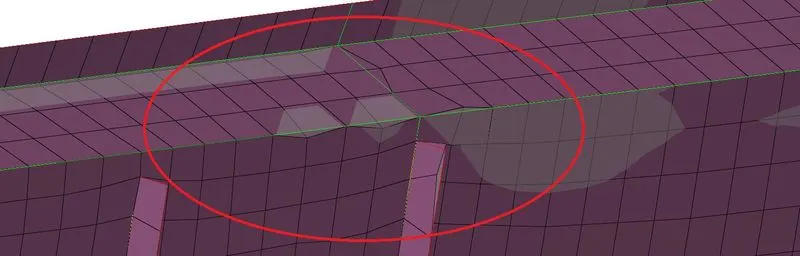
- Corrected
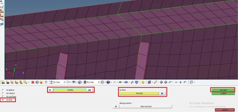
STEP 20: Translating node(s) to correct failed elements.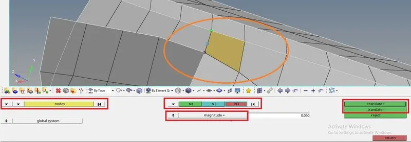
- Corrected
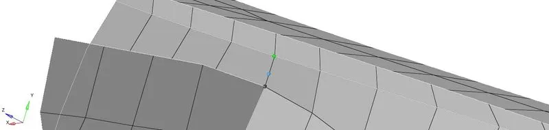
STEP 21: Moving Mid Surface and Mesh to one collector component as we have made it separate in step 2.
*Tool>Organise>surface>set current component>select dest component>move.
*Tool>Organise>elements>set current component>select dest component>move.
STEP 22: Finding free edges of elements after moving elements to single collector
- Finding disconnections between elements
*Shift+F3>components>select components>give tolerance>find edges>preview equivalence>equivalence.

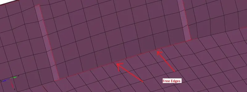
Connecting nodes of the elements by replace-with nodes panel. *F3

Corrected
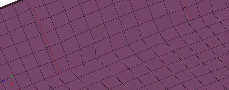
STEP 23: Assigning thickness to all the meshed elements
- Assigning thickness to elements can be done in two methods.
(A). Assigning thickness Manually. (NOTE:In this Project thickness is not assigned manually)
- Measure the thickness of the parent component by following step 5.
- Create Property collector in model tree panel.
- Rename it and mention it thickness
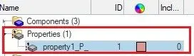
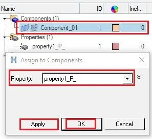
- Give the thickness manually in that particular collector details panel.

- Assigning Thickness
- Viewing Thickness of elements
*Toolbar>element colour mode (By Property)
*Toolbar>2D Detailed Element Representation
(B). Assigning Automatic thickness.
- NOTE: In this project we’ll go through Assigning thickness automatically.
*Toolbar>mesh>assign>mid mesh thickness>
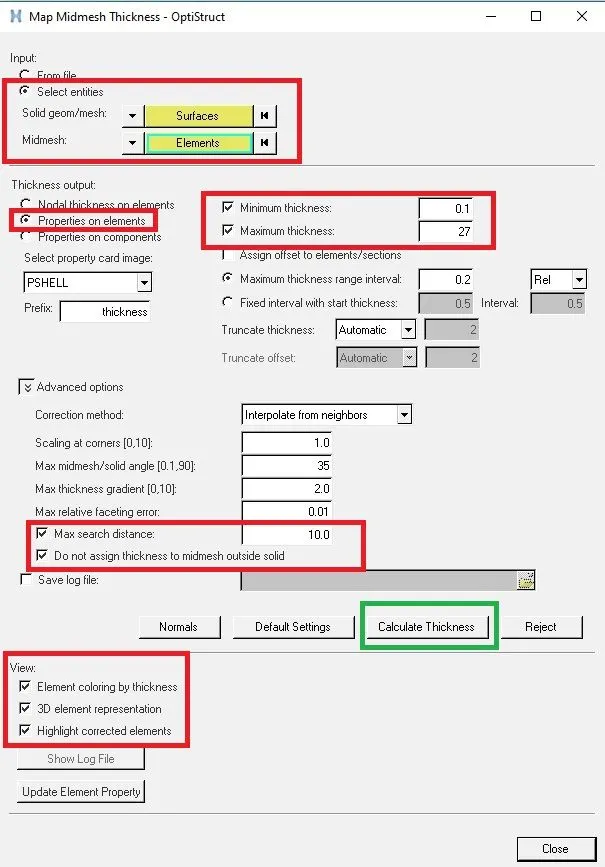
Select entities-It help us to select the entities in order to assign thickness.
Solid geom/mesh>Surface>select all the parent component surfaces.
Mid Mesh>Elements>select all the meshed elements.
Thickness output: This option will create a new property collector in the model tree.
Minimum thickness: To define a minimum thickness limiting value
Maximum thickness: To define a maximum thickness limiting value
Maximum search distance: We can restrict the maximum distance from which a desired thickness value is considered for correcting an incorrect thickness estimate.
Do not assign thickness to the mid mesh outside solid: It controls the thickness assignment outside the given geometry.
Calculate thickness: Assigning of thickness to the elements will start and it will take a while to complete it.
It undergoes following process automatically, seen is status bar-->
Creating mesh topology, detecting proximity,Initial meshing,meshing,oreanting normals,correcting thickness,finding fillets, Ready.
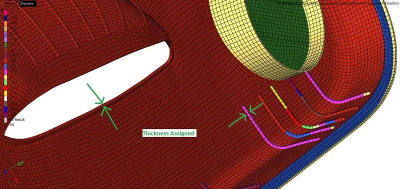
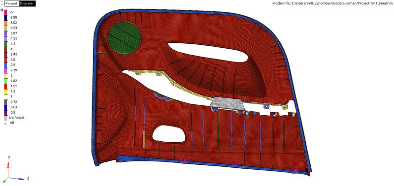
- Thickness assigned automatically
- Viewing Thickness of elements
*Toolbar>element colour mode (By Thickness)
*Toolbar>2D Detailed Element Representation
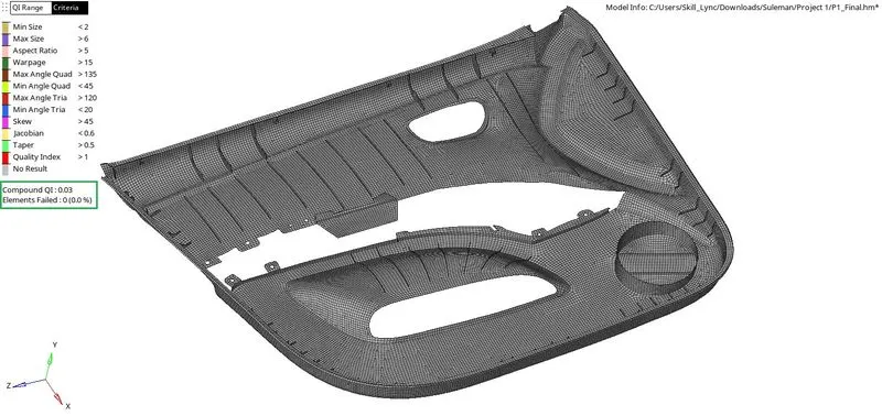
RESULTS:
- Final Elements Quality
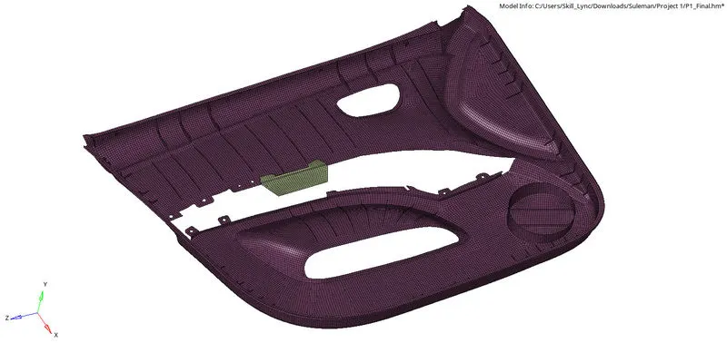
- Final 2D Mesh of Component
- Assignment of Thickness (2D)
LEARNINGS:
- Organising surfaces and elements. (Step 1, 2,7 and 21)
- Projecting nodes and lines to surface (Step 4 & 14(C))
- Measuring thickness of surfaces. (Step 5)
- Extracting the mid surface manually. (Step 8)
- Geometry cleanup using a quick edit panel. (Step 10)
- Defeaturing surfaces (Step 11)
- Obtaining midline (Step 12)
- Creating surface (Step 13)
- Connecting ribs to component (Step 14(A),(B),(C))
- 2D Meshing (Step 15)
- Setting up criteria file. (Step 17)
- Fixing failed elements using a quality index panel and remesh. (Step 18)
- Projecting element’s nodes to feature surfaces. (Step 19)
- Translating element’s node to fix failed elements (Step 20)
- Finding free edges of elements and fixing it (Step 22)
- Assigning thickness. (Step 23)