Week 12- Final project
AIM :
- To create a CAD model for door trim panel's parts by considering the given inputs of class A surface along with master section by following the design rules.
Objectives :
- To create individual tooling axis for the parts and perform draft analysis on the class A surface.
- To create the class B and class C surfaces from the given class A surface and then create a solid body.
- To Create the heats takes and dog house in the lower substrate considering the design rules from the master section provided.
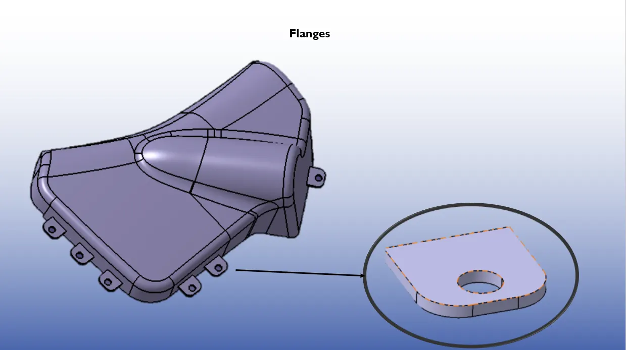
- To Create the Flanges to connect all the design features together considering the design rules.
- To perform draft analysis on the created solid part model with all engineering features.
procedure description :
- To segregate given surfaces into separate part body namely Lower Substrate , Arm Rest , Map Pocket , Bottle Holder and Pushpin.
- Analyse the input surface provided
- Class A surface as input surface
- Tooling axis creation
- Draft analysis of class A surface
- Class B surface creation
- Class C surface creation
- Solid surface body generation
- Draft analysis of the solid body
- creating the B side features
Given Class A Surface :
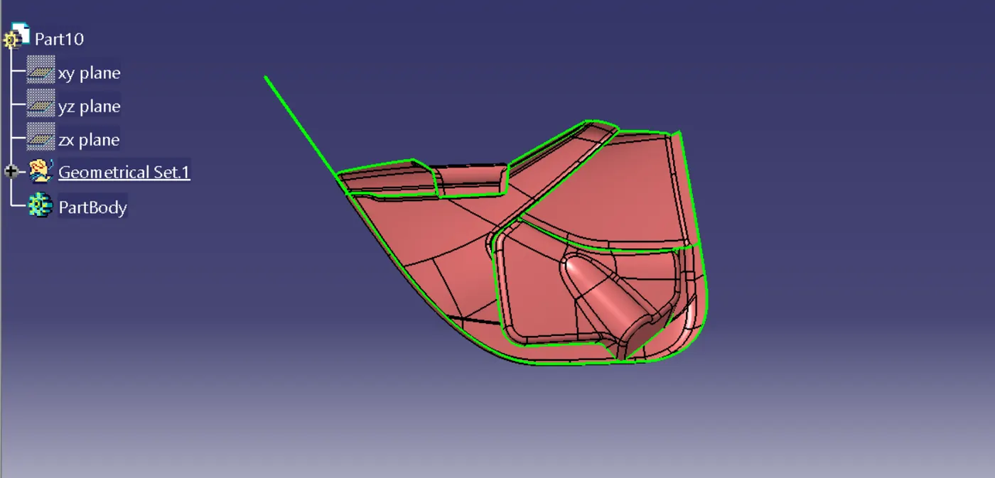
Class A arm rest surface :
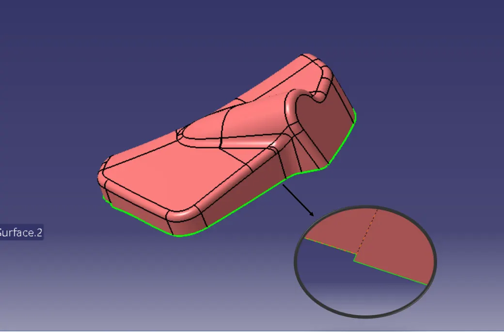
The A-surface or the styling surface is first checked for any gaps and other issues in its surfaces.
To check whether the surface has any open boundaries use the boundary feature then we can identify that there is an open patch or the surface which we need to work on it.
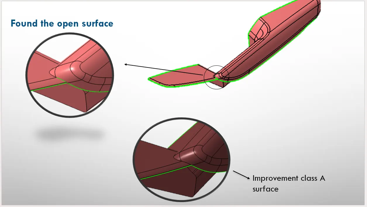
After completing the work of open connection, we checked the boundary of the surface to ensure the possibility of open surfaces.
As shown in above image I have improved given class A surface in surface workbench by using surface operation such as extract, extrapolation , trim etc.
Tooling axis creation:
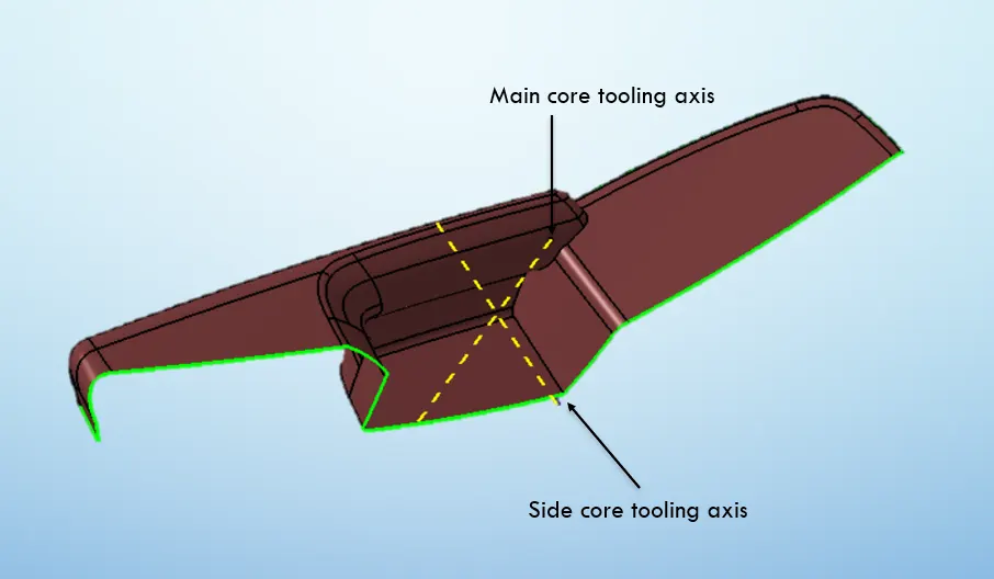
We need two tool molds to shape the arm rest. Some parts will be molded with the first tool mold and the rest with the second.
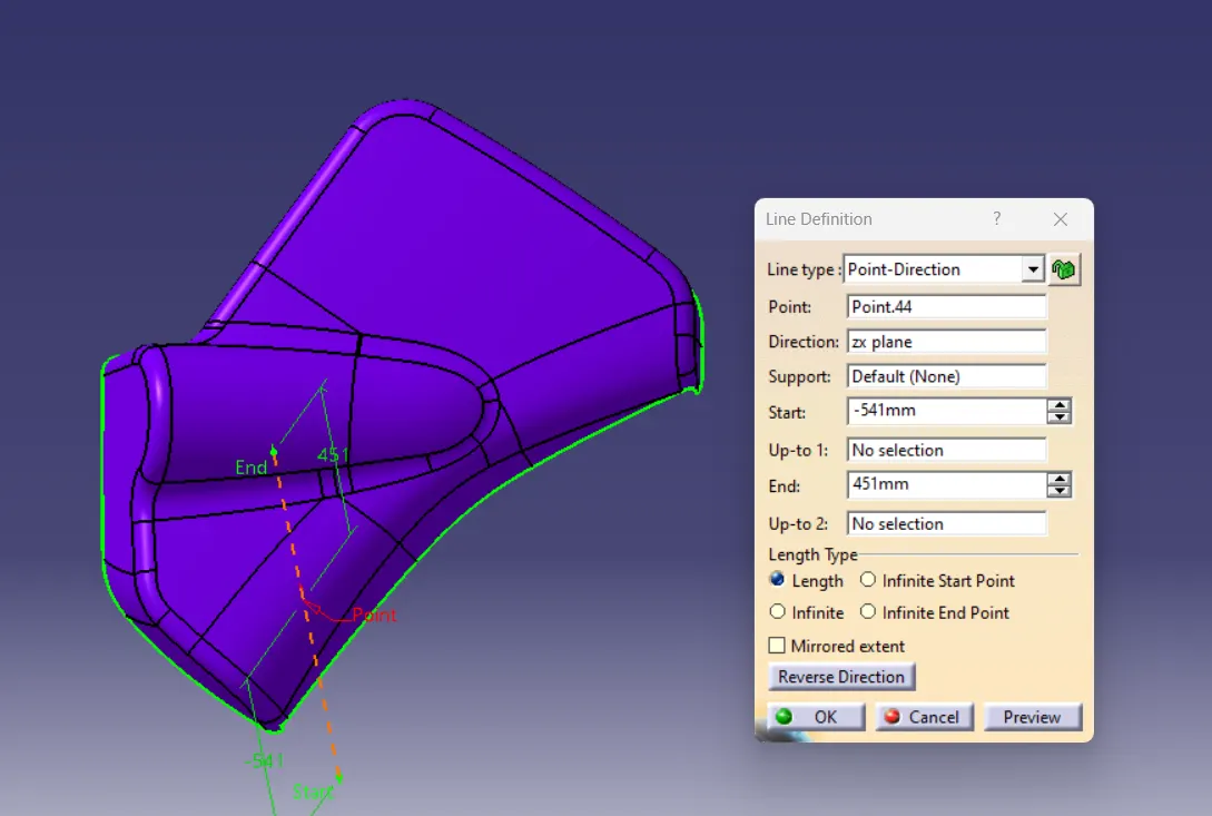
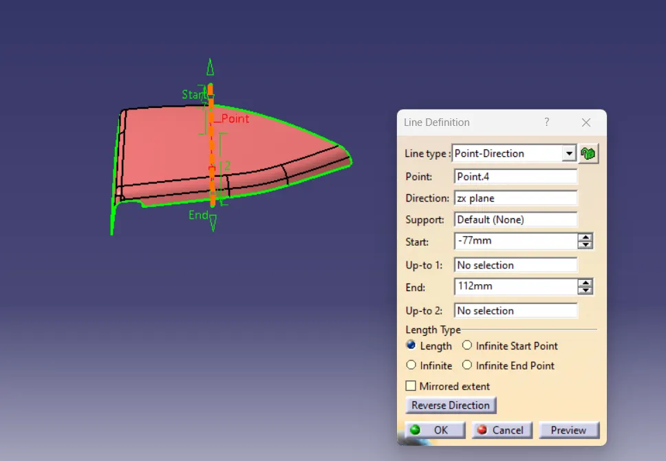
First we need to create a plane on the surface of class A, then using the plane we create a line along the Z axis. This is the main tool axis.
We created a line along the Y axis on the surface of class A. This is the side core axis.
Draft Analysis of Class A :
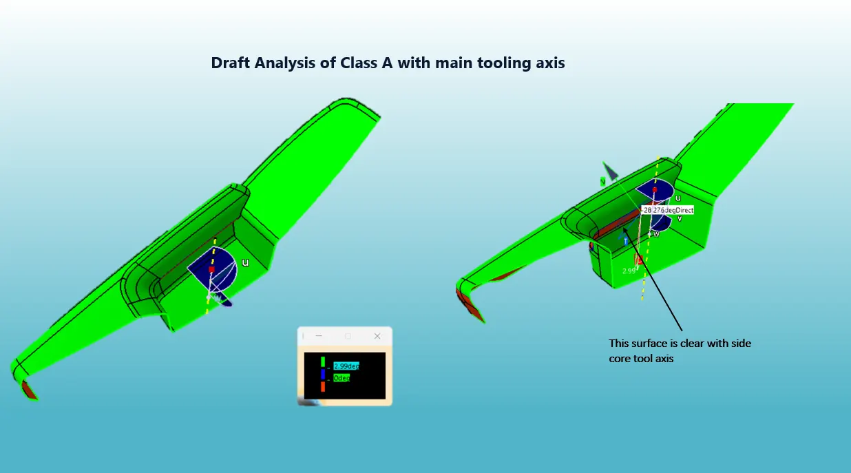
Draft analysis is done after determining the tooling axis on the Class-A surface, Draft analysis is used on the Class-A surface to check whether the minimum draft angle 3 degrees is maintained or not.
Given a surface angle of minimum 3 degrees, we proceed to the next step.
Class B surface :
The Class-B surface is the secondary surface in the plastic component. Class B-Surface is extracted from the A-surface.
Class B surface is created by offsetting class A surface by 2.5 mm as per the master section.
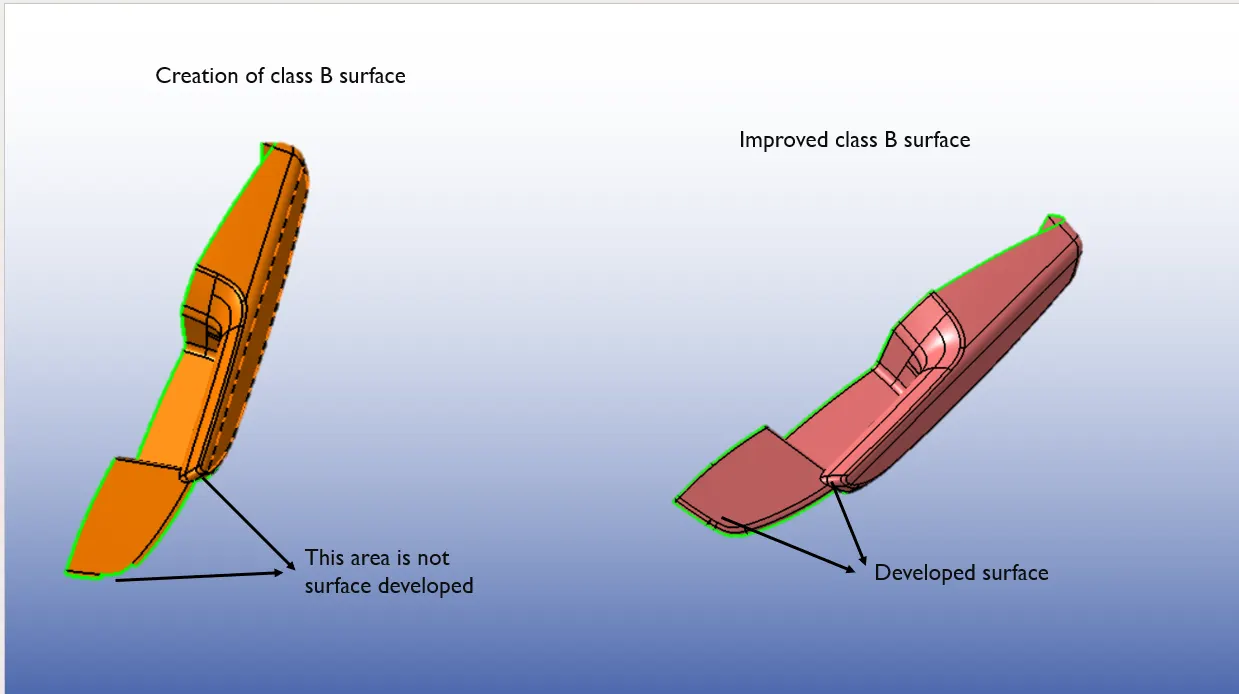
Some parts were missing from the created class b surface so i used extract ,extrapolate, offset, and trim commands to fix that.
Class C surface :
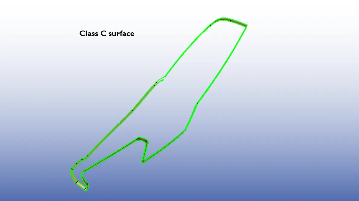
C surface is the connecting surface of Class A and Class B surface. By using Sweep we created the Class C surface. The class C surface is created by giving a minimum draft angle of 3mm in the sweep command.
Creation of closed body Arm Rest :
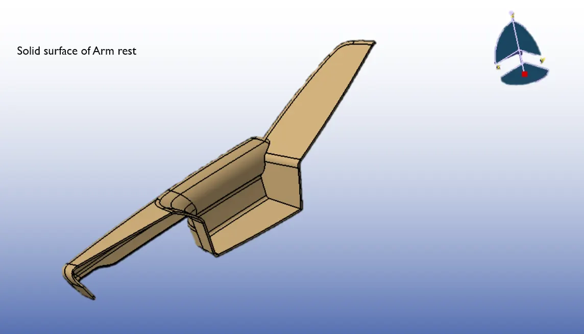
By trimming join of Class A ,C with Class B surface we get close body.
Creation of flanges on Arm Rest:
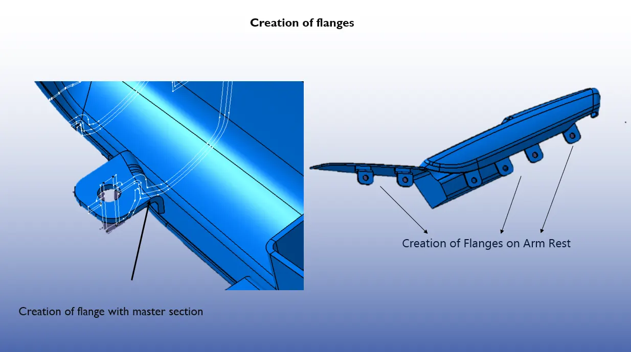
These flanges will be build on the components for the fitment purpose with lower substrate.
We created the flanges on the arm rest using the master section.
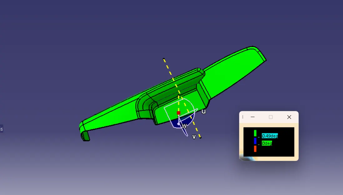
A draft Analysis on Solid Body of Arm Rest:
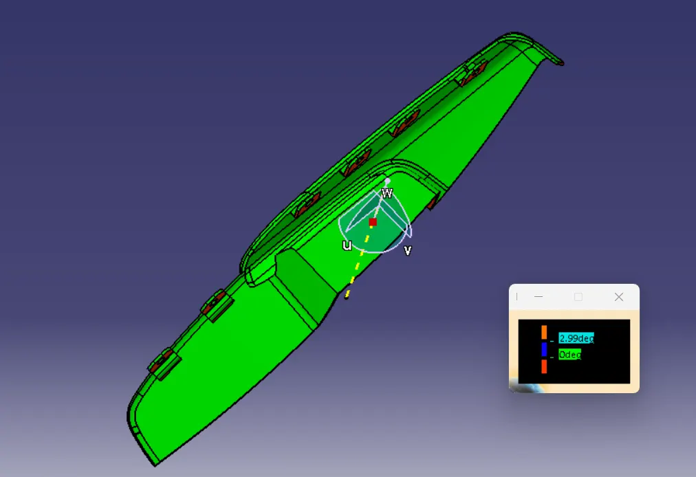
A draft analysis of a rigid body with a draft angle of 3 degrees was performed. If we don't give a draft analysis to the component, it hits the axis and the friction compounds damage our part, so we give some draft angle to overcome this problem.
Class A side
B side draft analysis;
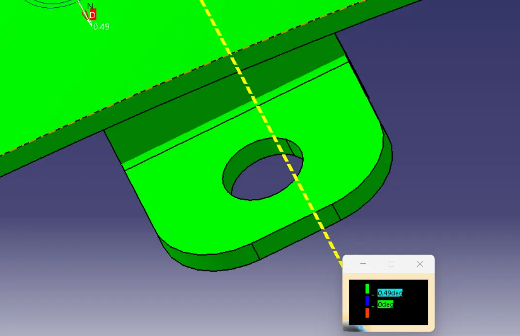
Draft analysis on flanges is checked at 0.5 degree scale.
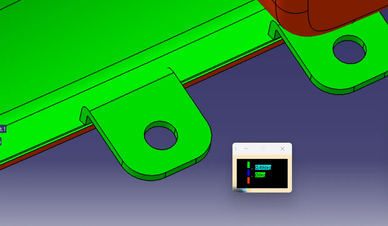
Following images give the idea about is it manufacturable or not.
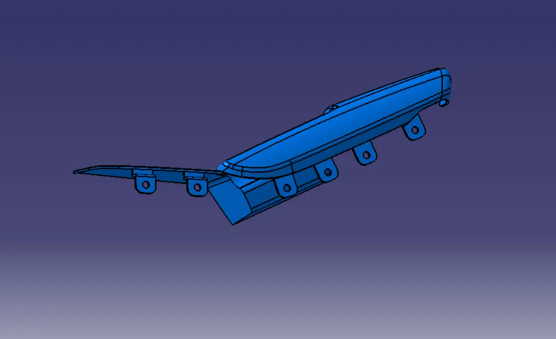
Arm Rest After creation :
LOWER SUBSTRATE :
Class A Lower substrate surface :
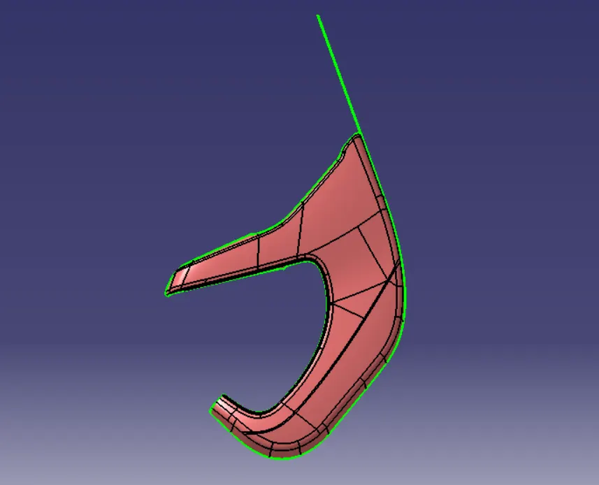
Creation of tooling axis :
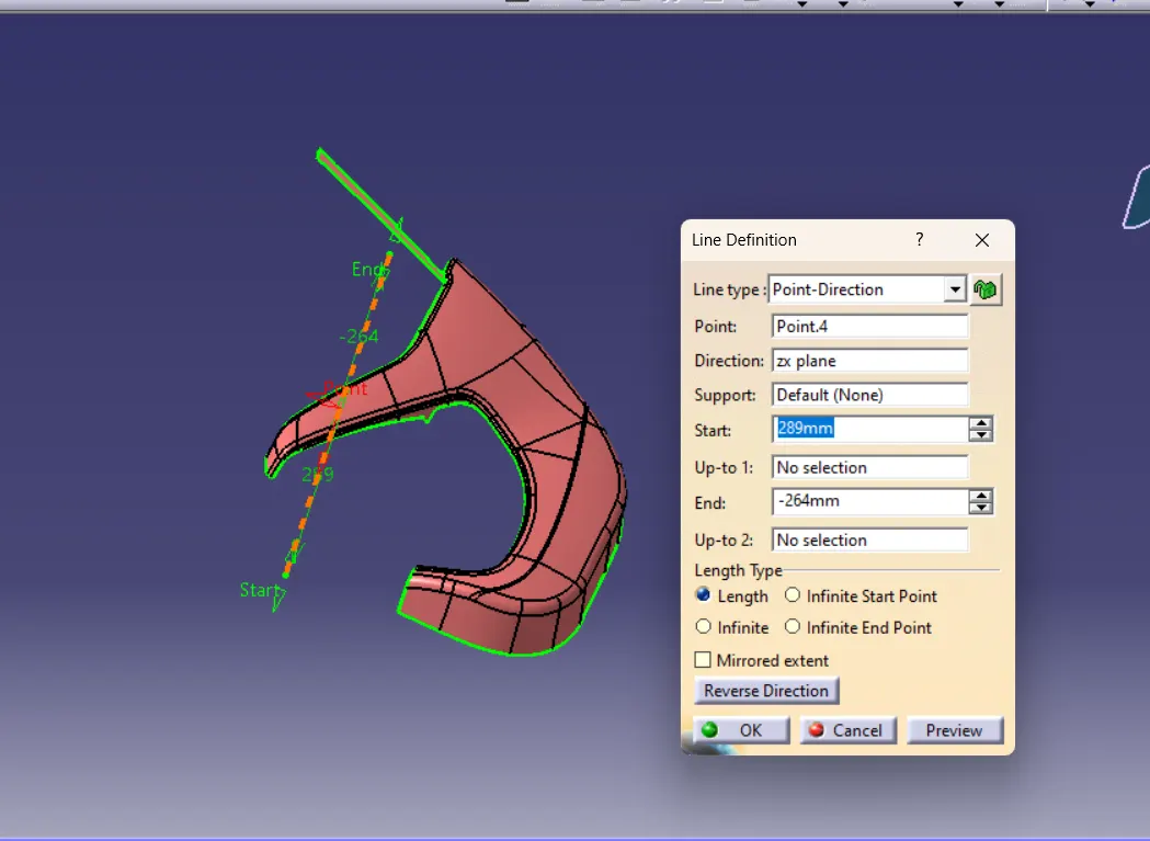
Draft Analysis on class A :
All surface areas shall have a minimum draft of 3 degrees.
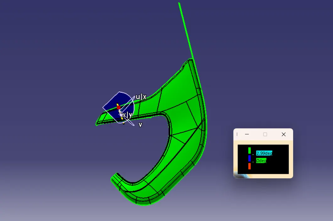
From above draft analysis we say that given class A is of good quality.
Creation of Class B surface :
Class B created by offsetting class A by 2.5 mm.
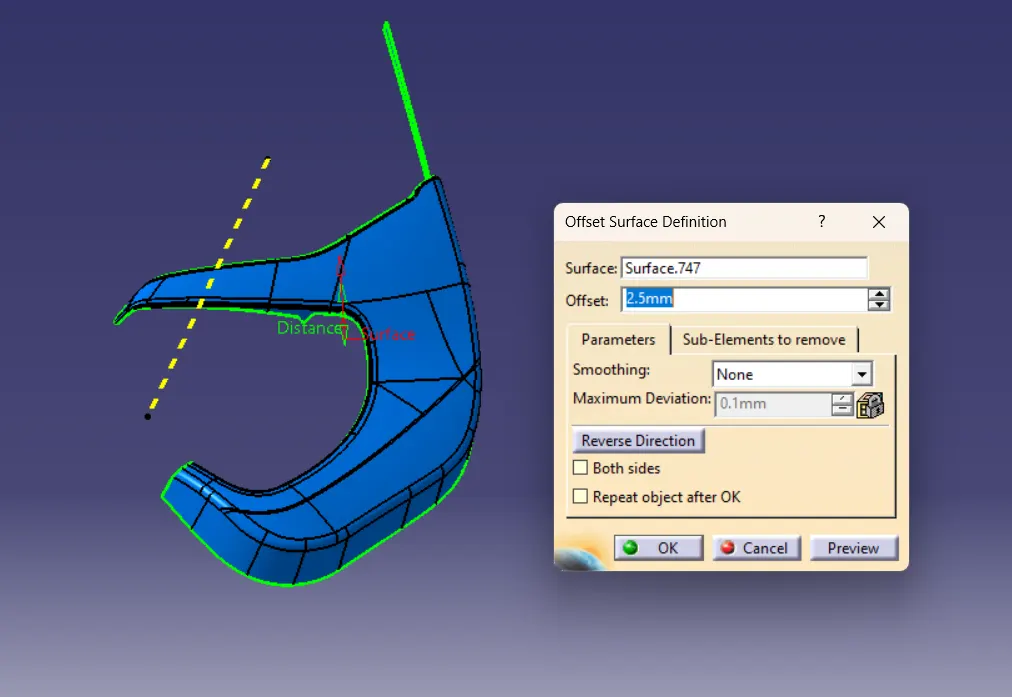
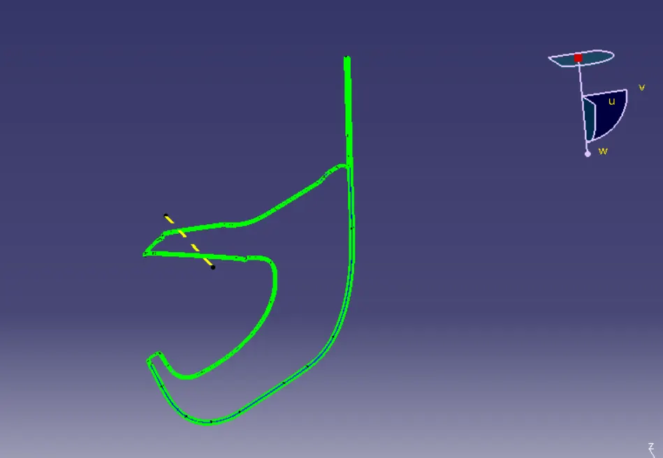
Creation of Class C :
A class B surface is a surface created with the help of a class A surface.
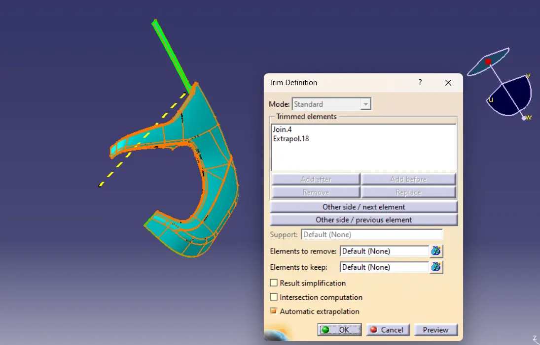
Creation of Closed Body:
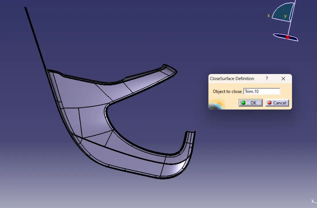
The final trim is obtained by trimming the class B with the class A & C surface. The final check to ensure the proper closeness of surface with the boundary command.
Solid body of Lower substrate :
Usage of heat stake :
- Heat stake is a thermal process that joins two or more parts together.
- Heat Staking makes it easy to bond metal to plastic and is commonly used in high volume/low cost applications such as automotive, IT and consumer appliances.
- Similar and dissimilar materials may be joined.
Creation of Heat stake :
Creating a Heat stake with the help of master section.
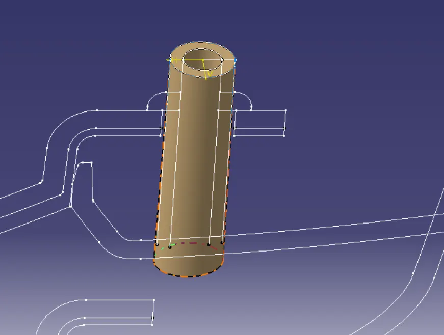
A draft of 0.5 degrees is given in the heat stake.
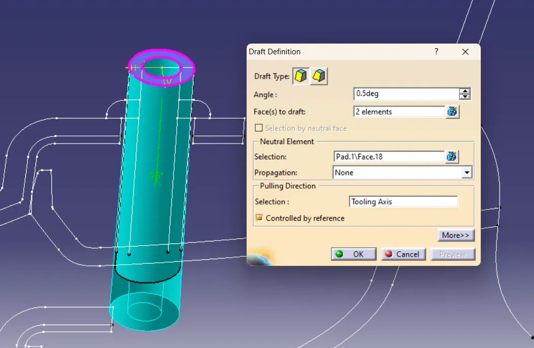
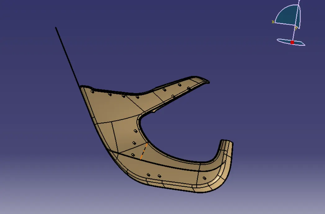
We have placed 14 heat stakes in the model based on the reference points created by estimation.
Dog House :
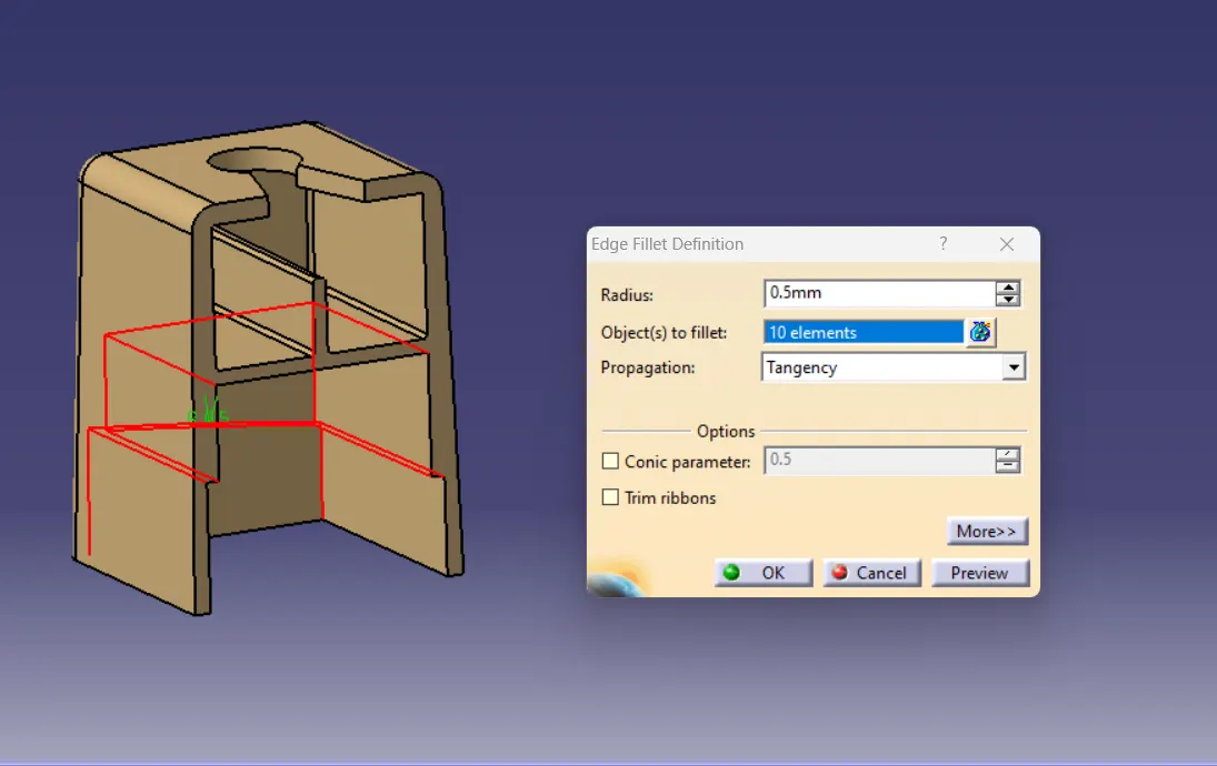
The two main purposes of a dog house are to avoid sink marks and to house various other engineering features like screw boss, locators, push clips etc.
The dog house should follow certain design rules which are stated below :
- Doghouse wall thickness at the intersection of the part wall (C) should be 40% or less than the main wall stock (T).
- The height of ( B ) should be between 3.0 – 6.0 mm.
- Outer surface of dog house must have a draft angle of 3 degrees.
- Inner surface of dog house must have a draft angle of 0.5 degrees.
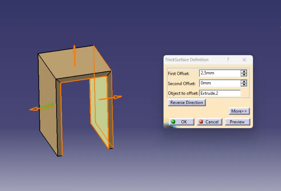
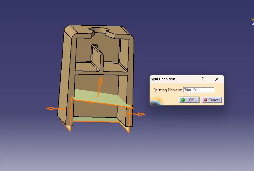
Creation of Dog House :
A master section or engineering drawing is followed to build a dog house.
Draft Analysis on Dog House :
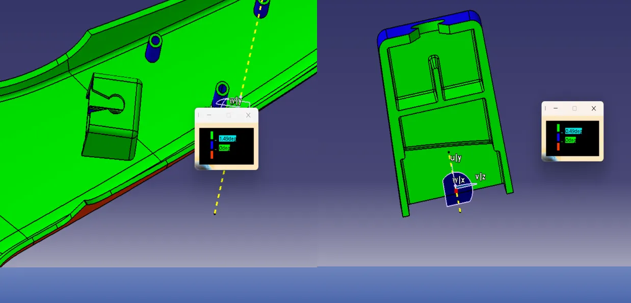
From above draft analysis we noticed that outer surfaces of dog house have minimum draft of 1.5 degree and inner surfaces with minimum draft of 0.5 degree.
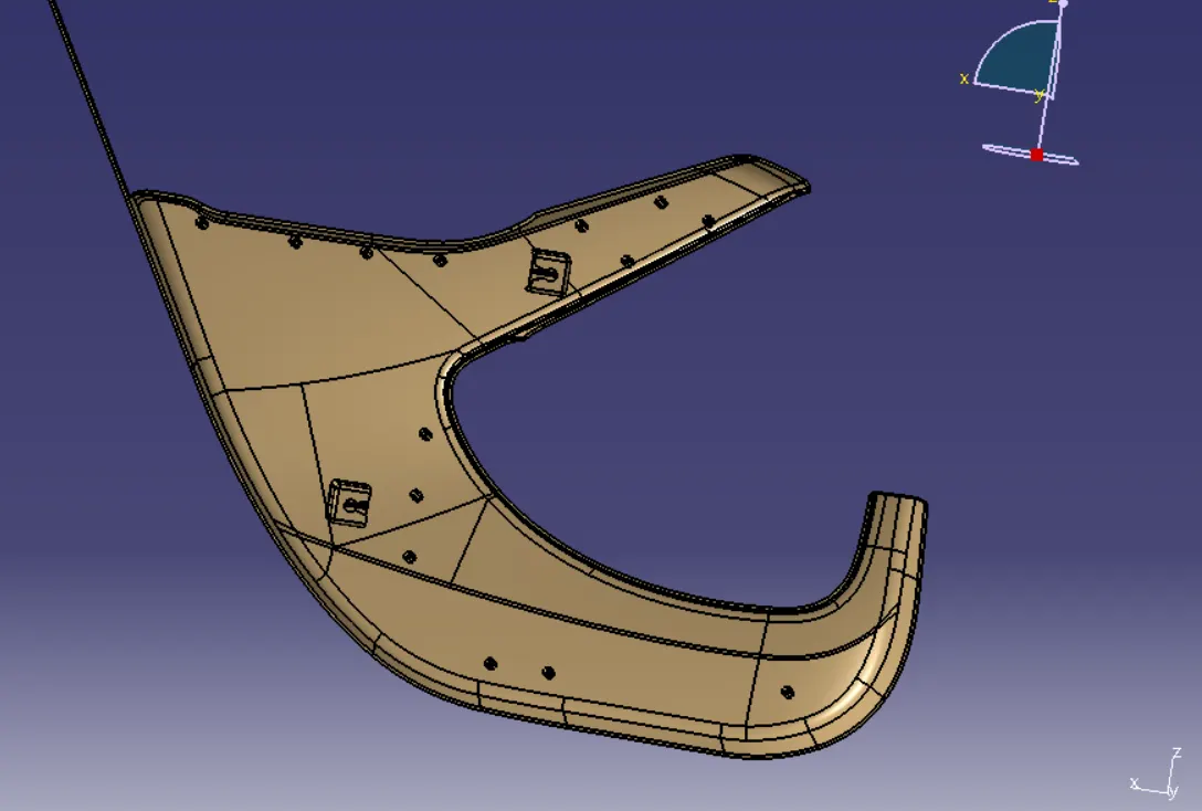
Lower substrate After creation :
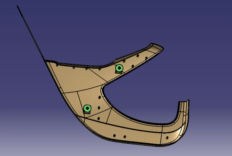
Push Pin :
Assembling the push pins to the dog houses.
BOTTLE HOLDER
Class A Surface of Bottle Holder:
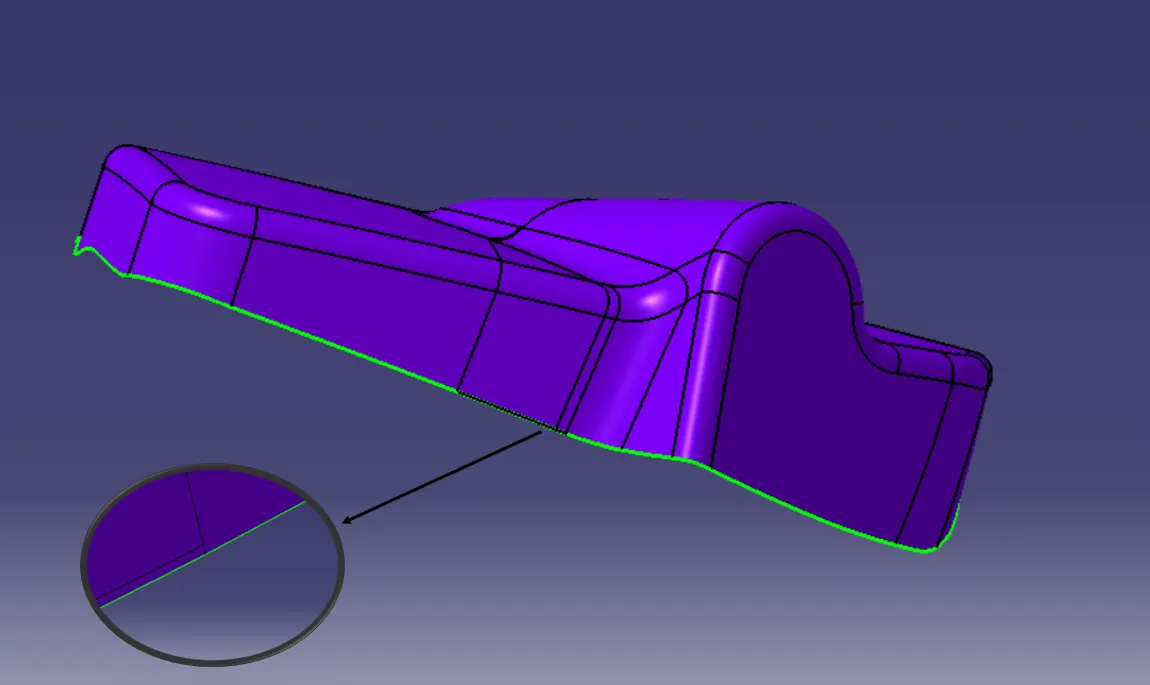
Check quality of Class A
Improved Class A surface :
Creation of Tooling Axis :
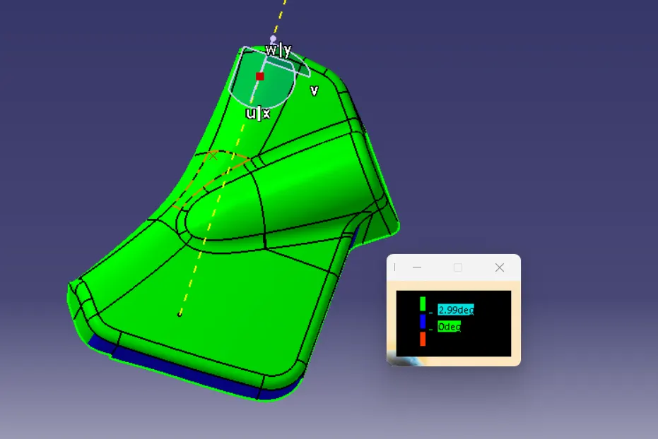
Draft Analysis on Class A :
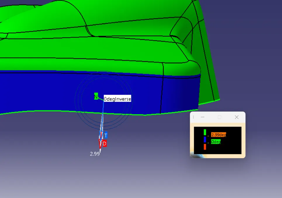
From above draft analysis we notice that some area are not have minimum 3 degree draft. Blue colour area shows negative draft for that we have to informed styling team for improvement in class A.
Creation of Class B :
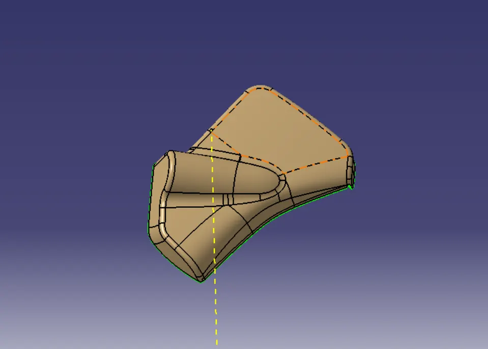
For creating Class B surface we have to offset it by 2.5 mm as shown in above image.
Creation of Class C :
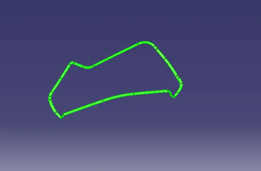
For creating class C surface we have to use sweep feature of surface creation.
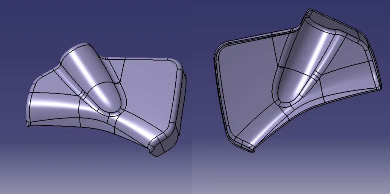
Solid Body of Bottle holder :
Creation of Flanges :
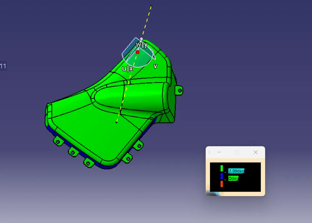
Draft Analysis on solid body of Bottle Holder :
Draft analysis on flanges of Bottle Holder :
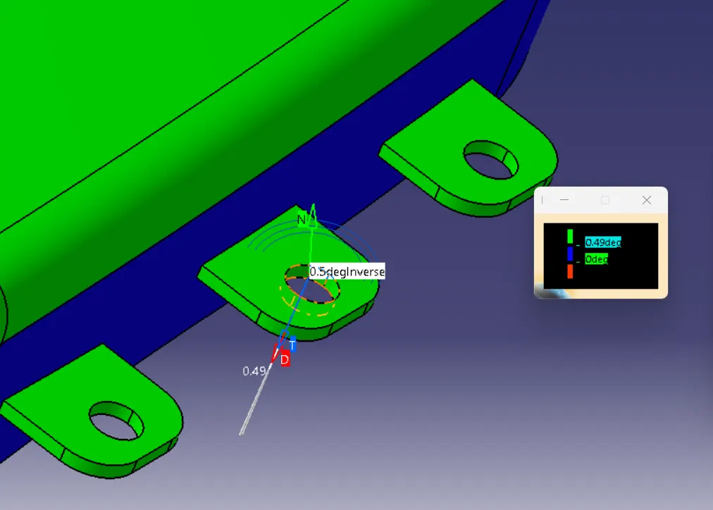
From the above draft analysis, we noticed that the bottle holder part is not as required, so we need to inform the styling team.
MAP POCKET
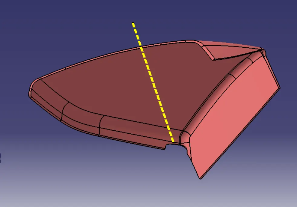
Class A Surface :
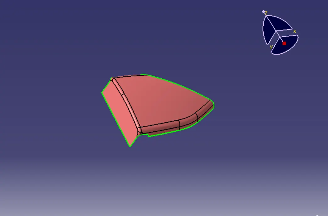
Creation of Tooling Axis :
Draft Analysis on Class A :
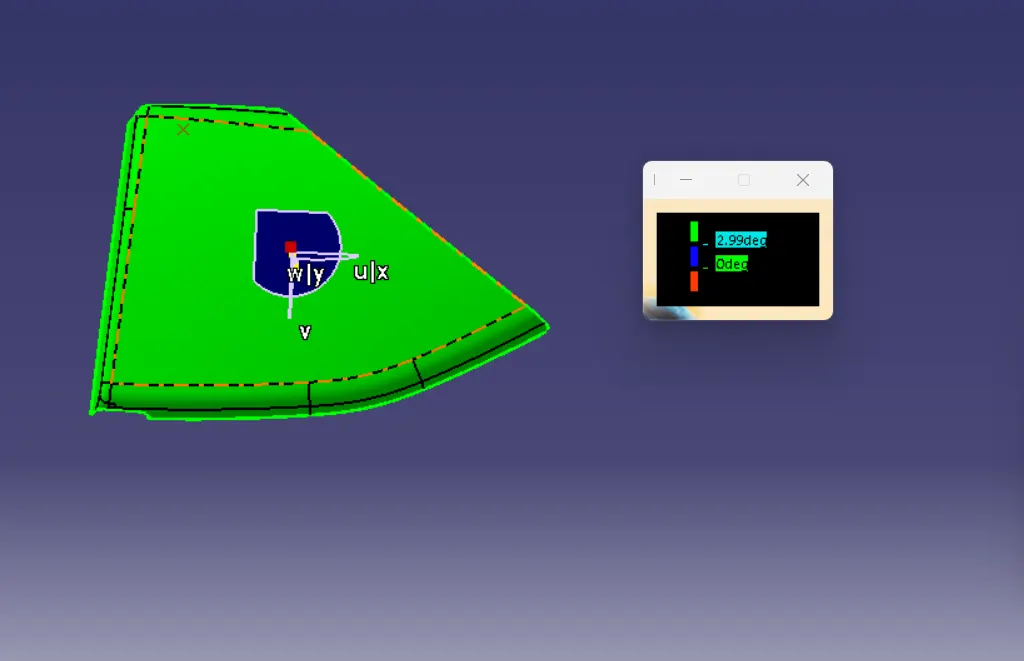
The draft analysis above has a minimum draft of 3 degrees on all surfaces. So we do the next process.
Creation of Class B surface :
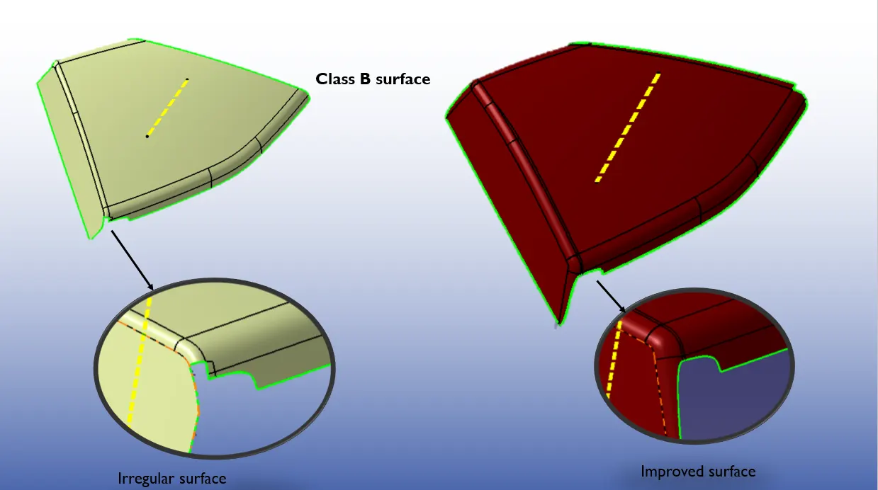
Class B surface is created by offsetting class A surface by 2.5 mm as per the master section. Some parts are not available after offset. This patches are closed by surface creation features such as multi section surface, extrapolate, join etc.
Creation of Class C surface :
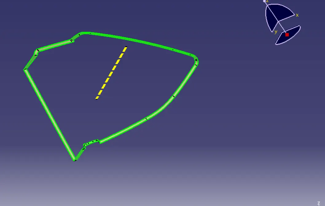
Class A boundary should be extracted first, and then the Class A extracted boundary should be swept along the draft direction at an angle of 3 degrees. We get a class - C surface.
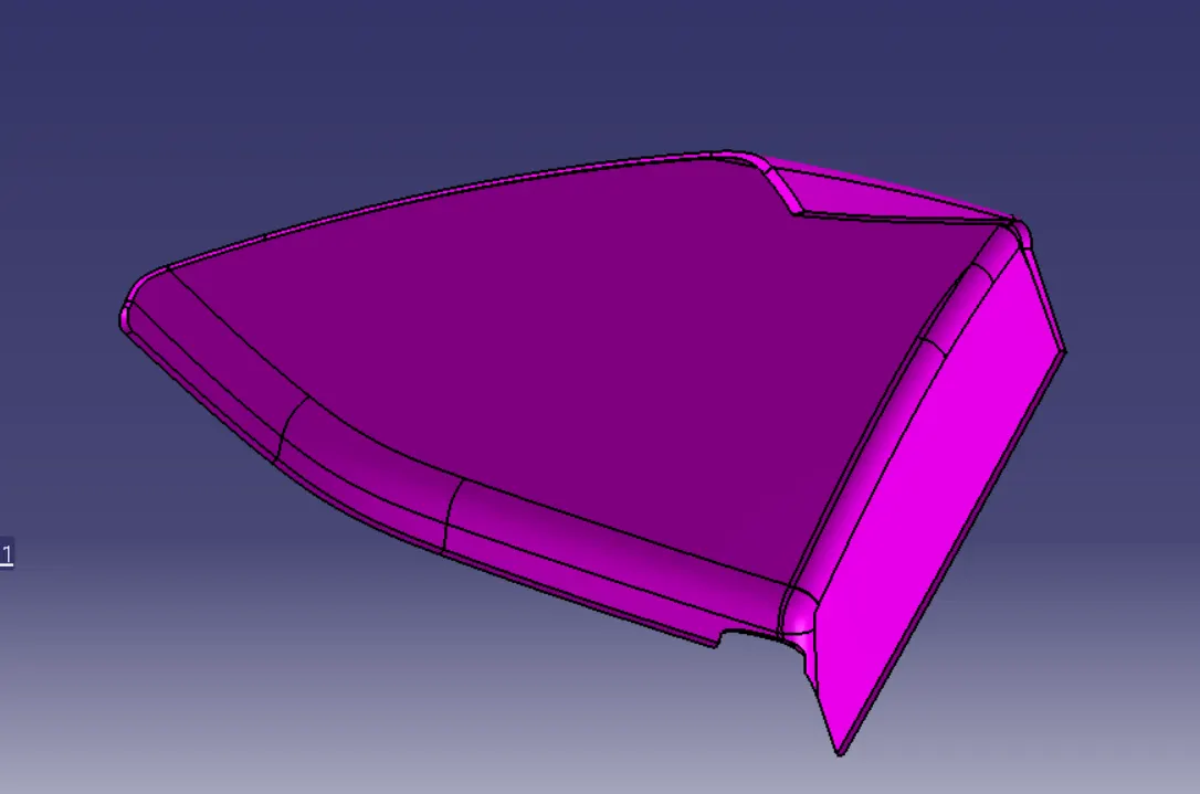
Final Closed body and Solid Body of Map Pocket :
Creation of Flanges :
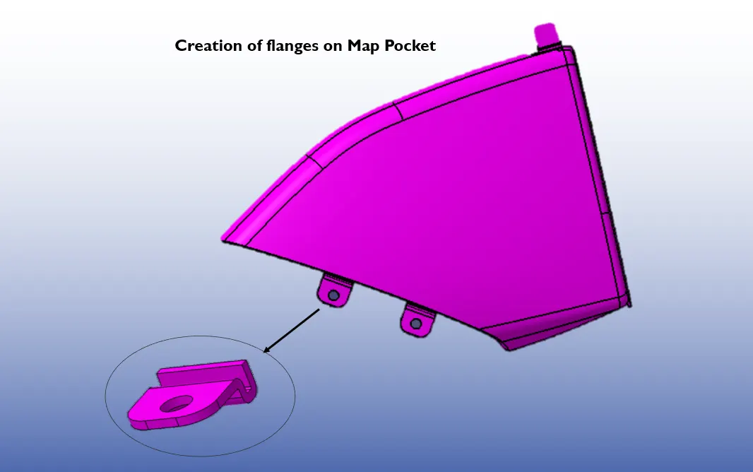
Draft Analysis on Final Body :
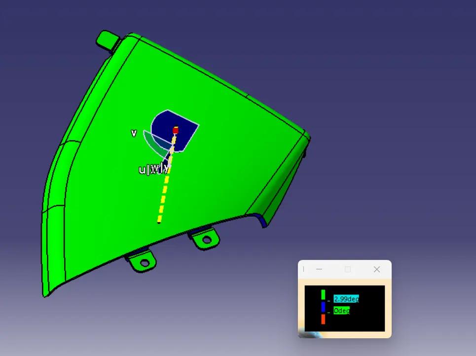
All areas except this area have a minimum draft of 3 degrees
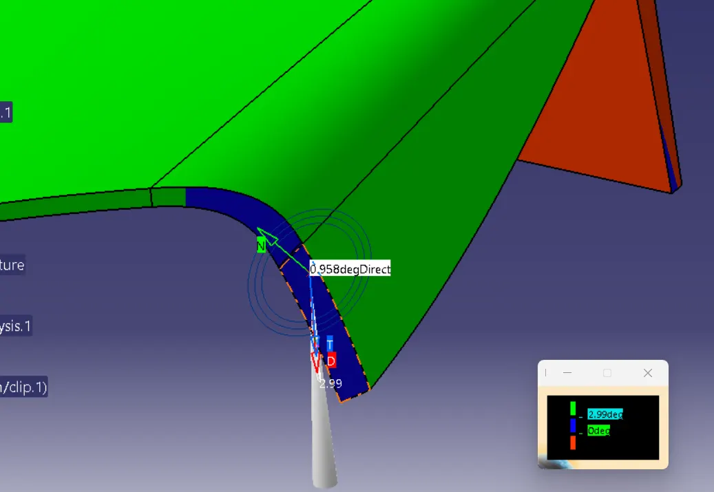
Draft Analysis on Flanges :
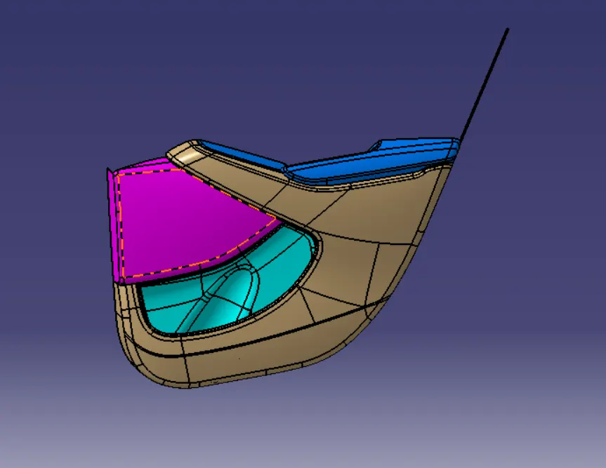
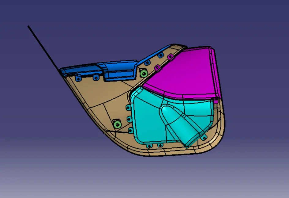
Final Assembly:
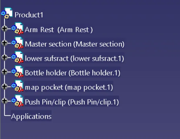
Tree Structure :
CONCLUSION :
From this project we have learned how to create CAD model for plastics parts by considering design rule.