Week 12- Final project
Final Project - Development of a Door Trim panel
OBJECTIVE: The objective of the project is to develop a Door Trim panel with CAD modelling techniques by applying industry design standards particularly followed by OEM and Tier-1 companies. The project includes creating a Class A surface with nominal thickness based on master sections, building an effective attachment strategy by integrating push pins with a dog house for attaching the lower substrate to the door panel and utilizing the heat stakes for part-to-part attachment. The product output comprises generating a thickened part utilizing master sections as a reference and integrating mounting features according to design guidelines.
MAIN PROJECT:
Door Panel Design:
Given:
Class-A Surface: Class-A surfaces refer to high-quality surfaces on a product or tooling that are critical for achieving a flawless and aesthetically pleasing finish. This surface emerges from the creative strokes of freehand sketchers by visualizing the essence of conceptual ideas. The precisely refined sketch is subsequently digitalized, and seamlessly transformed into a sophisticated 3D surface through the utilization of specialized software such as Alias.
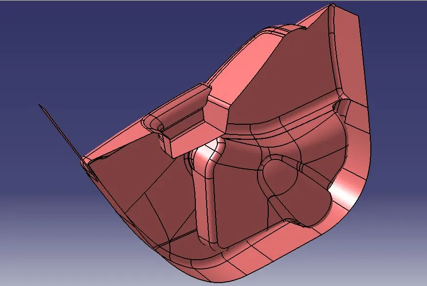
Arm Rest:
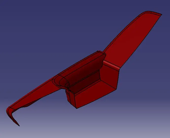
Lower Substrate:
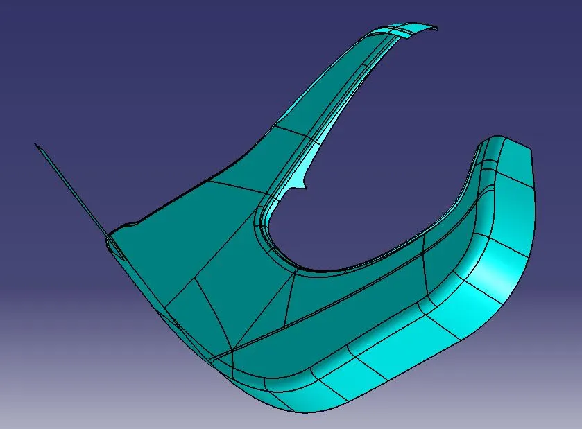
Map Pocket:
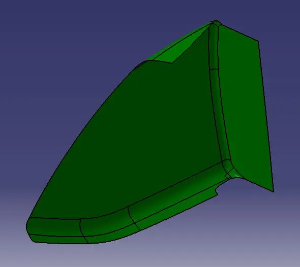
Bottle Holder:
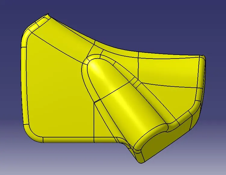
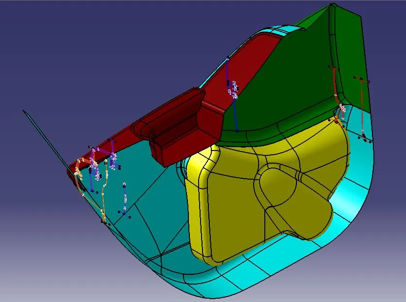
Master Section: A Master Section is a 2D representation or cross-sectional profile, defining key dimensions and features used as a blueprint for creating a corresponding 3D model. Designers utilize the master section as a starting point in the modelling process. It acts as a reference guide, ensuring that the design criteria are consistently maintained throughout the creation of the 3D model. The master section offers guidance for shaping surfaces or solid bodies, positioning the placement and orientation of significant features to align with the desired design.
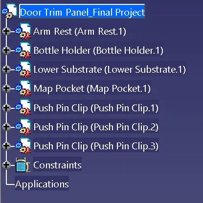
High-Level Tree-Structure of 3D CATPart:
A] Arm Rest Design:
Surface Improvement:
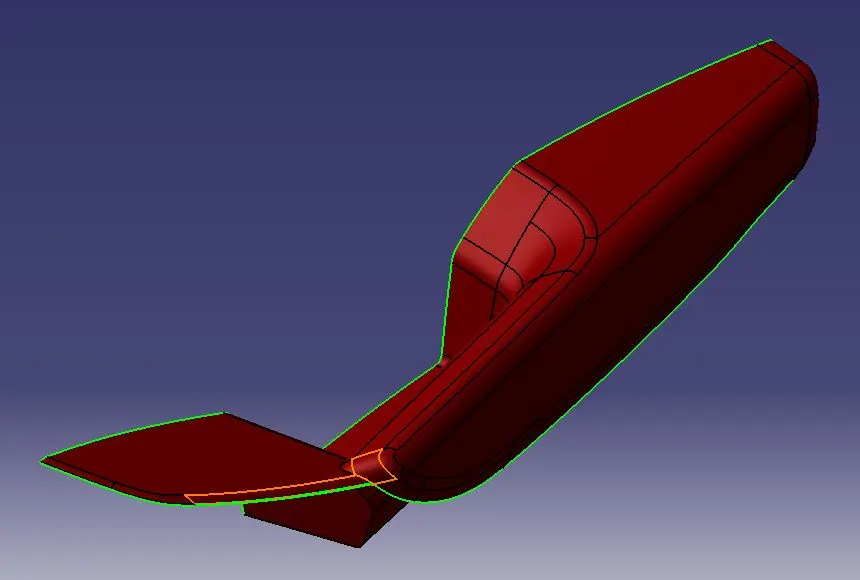
STEP-1: The given surface is examined and noticed that there were some surface discontinuities, which are highlighted and shown in the below image. These surface discontinuities are supposed to be rectified.
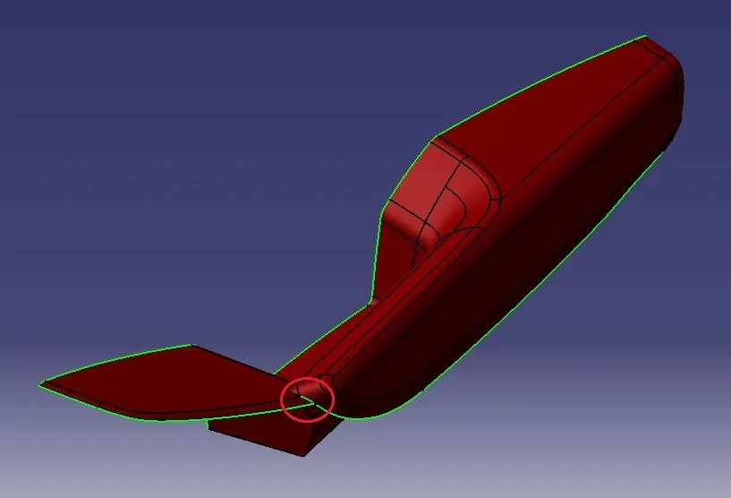
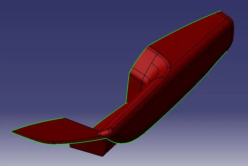
STEP-2: The surfaces around the internal gap are extracted, extrapolated, trimmed and joined with the existing surface to rectify the internal surface gaps in the provided surface.
Class-A Surface Creation:
STEP-1: Upon checking the Master Section, it was found that the provided surface was an armrest cushioning surface positioned 2mm above the Class-A Surface.
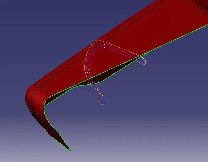
STEP-2: Direct offset of the given surface by 2 mm downwards fails at intricate areas, so extract the improved surface into 2 parts and offset it by 2 mm.
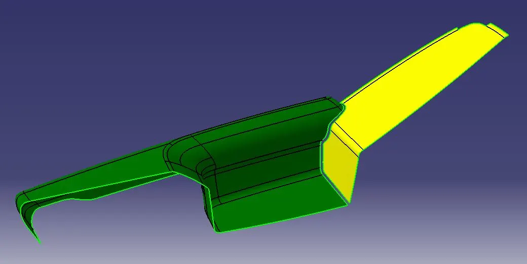
STEP-3: The surface that failed to generate during offset was created using the Multi-Sections Surface command, joined with the existing surface and extrapolated. The other part of the surface also was rectified using various commands and extrapolated up to a certain mm.
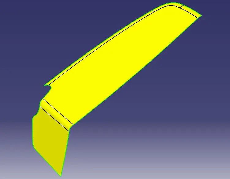
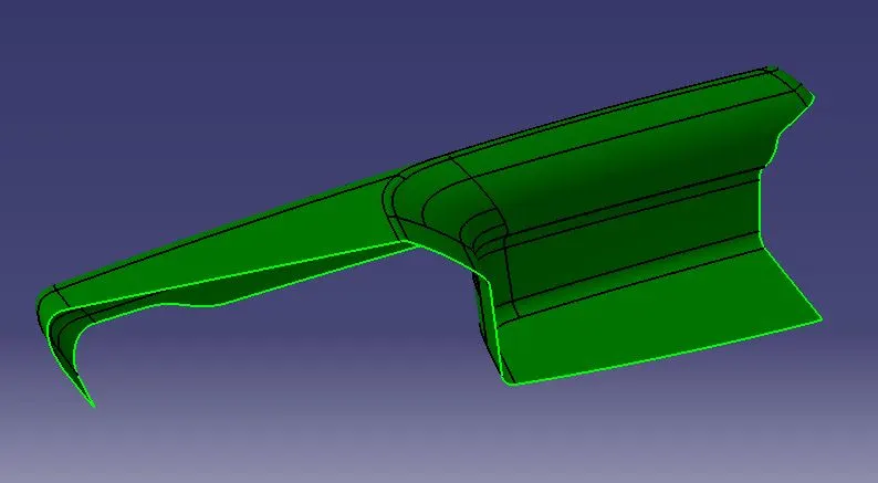
STEP-4: Finally, both surfaces are trimmed and form the Class-A surface.
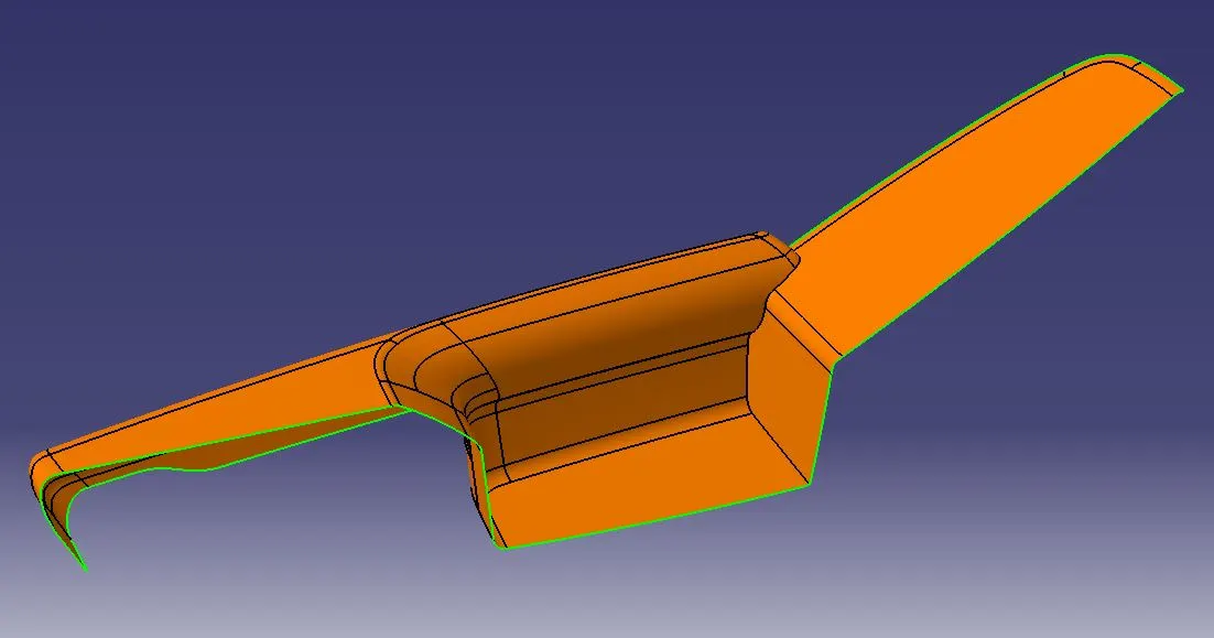
Tooling Axis Creation:
STEP-1: The tooling axis was constructed by bisecting the lines taken from the intersection of the Class-A Surface and the ZX plane.
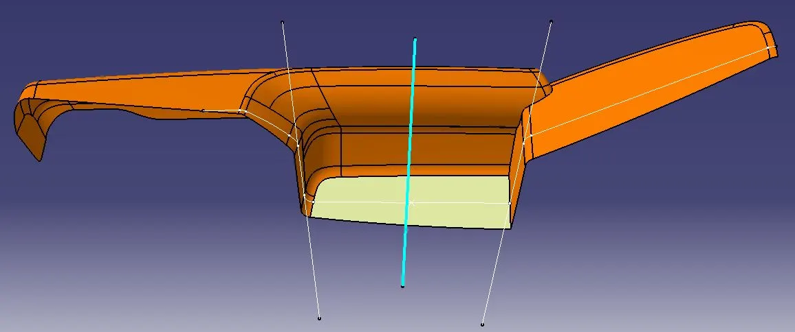
Class-A Surface Draft Analysis:
Before generating the part model, conducting a Class-A Surface draft analysis is important to check the manufacturing complexity and to ensure and understand the potential challenges.
The drafting possibilities are based on various axes.
X-axis: Not possible to produce.
Y-axis: Not possible to produce.
Z-axis: Cheap and easy way to produce the component.
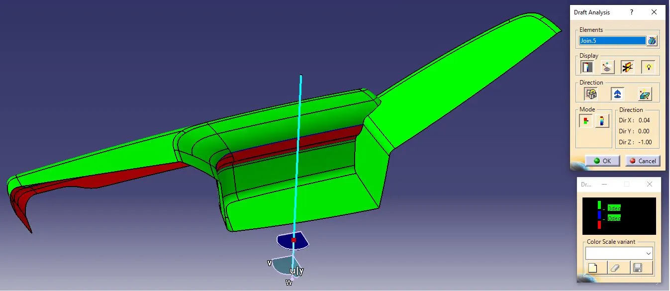
The tooling axis did not pass the 3-deg draft angle criteria for manufacturing the armrest component in two sections. This issue was supposed to be reported to the Styling Team and they will carry out the necessary modification. Since the project's objective was to analyze the Class-A Surface and design the thickened part with B-side features, the next steps were progressed accordingly.
Class B Surface:
Class-B surfaces are interior surfaces of the part body and it does not require the same level of visual perfection as Class-A surfaces. While Class-A surfaces are primarily concerned with flawless appearance and are typically used for visible exterior parts of a product, Class-B surfaces are utilized for areas where visual perfection is not as critical as it may also contain B-side features like ribs, screw bosses and dog houses.
Class-B Surface Creation:
STEP-1: Direct offset of the Class-A surface by 2.5 mm downwards fails at fillet and intricate areas, so extracted the Class-A surface into 4 parts and offset it by 2.5 mm.
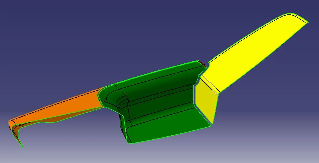
STEP-2: The offset surfaces 1 and 2 are extrapolated, trimmed and provided the edge fillet as required.
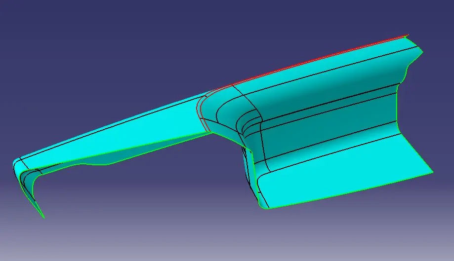
STEP-3: The small path of a surface was split from the surface and extrapolated the surface along one edge by a certain mm.
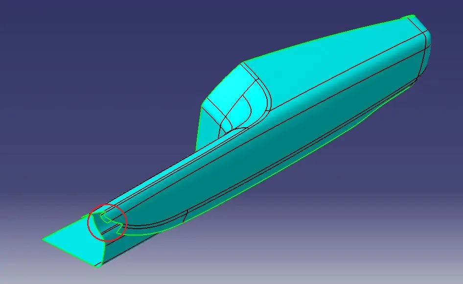
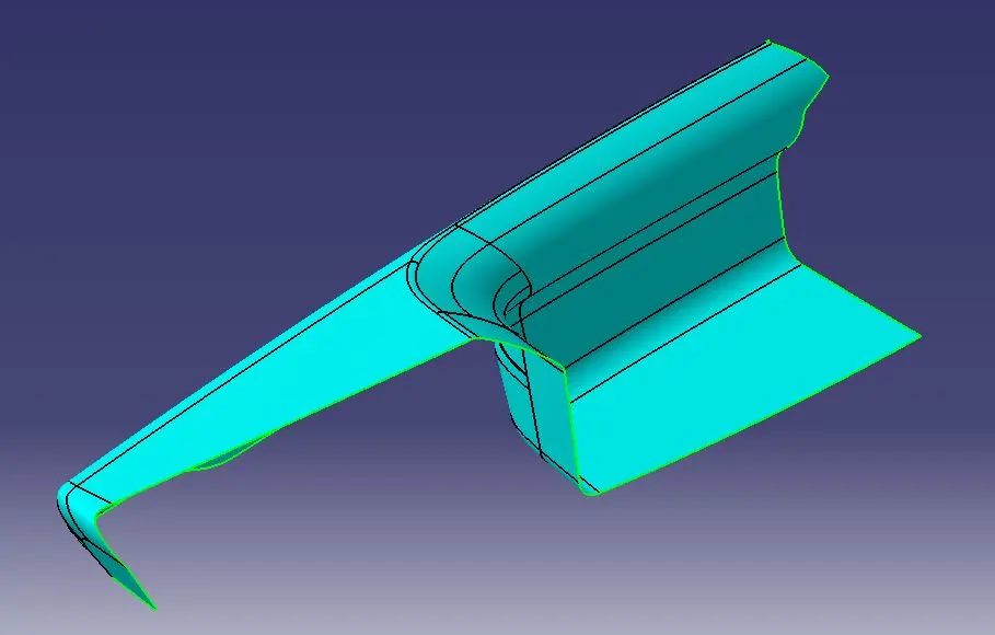
STEP-4: The next offset surface is the critical portion, so they were disassembled into individual paths and each of them was handled separately and joined back.
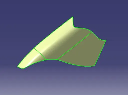
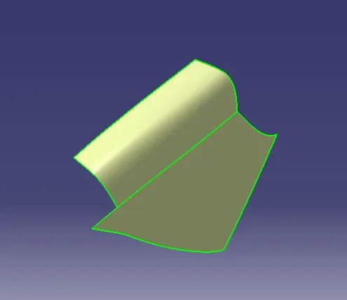
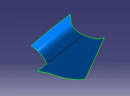
STEP-5: The missed surfaces between offset surfaces are created using the Multi-Sections Surface command and all of the surfaces are joined into a single one.
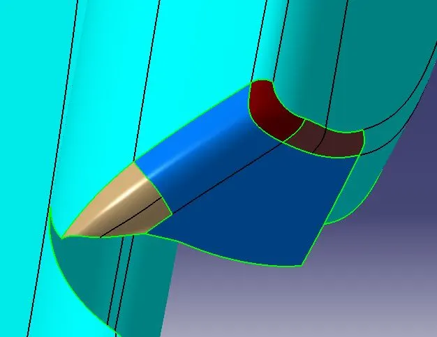
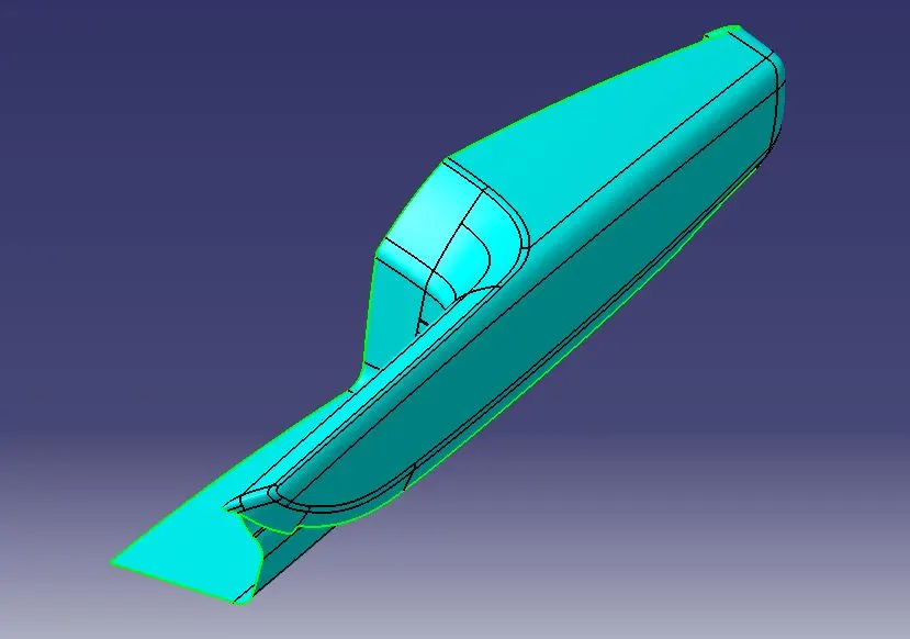
STEP-6: The last offset was rectified and extrapolated by a certain mm to trim with the previous surface. At last, the Class-B Surface was formed.
Class C Surface:
Class-C surfaces are primarily functional and may have fewer aesthetic requirements compared to Class-A Surface. These surfaces are often used in areas of a product where appearance is not a significant concern, and the primary focus is on meeting functional and manufacturing requirements.
Class-C Surface Creation:
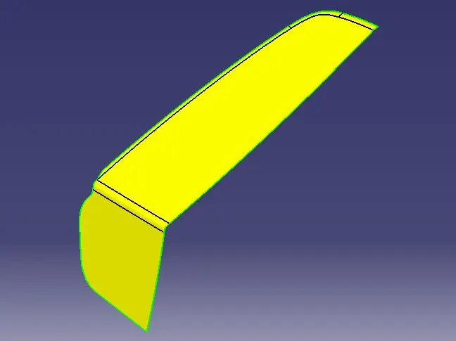
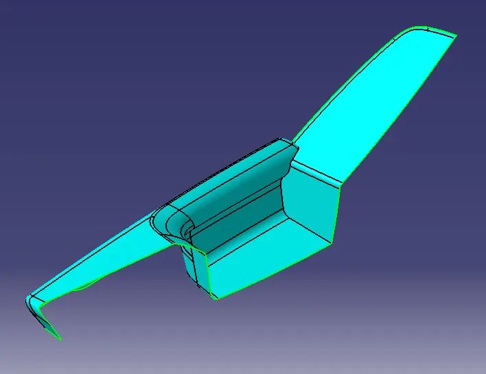
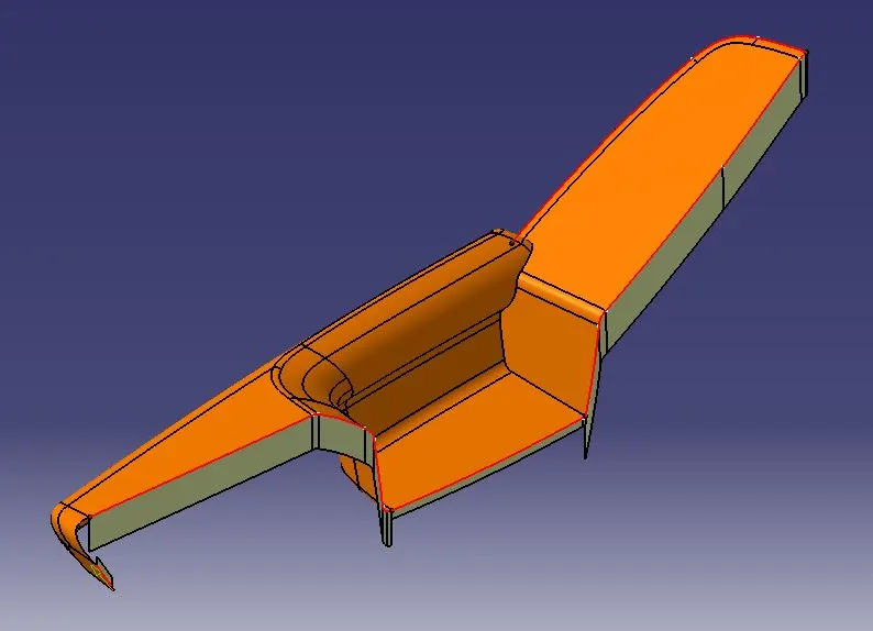
STEP-1: Boundaries are taken with limits one by one on Class-A Surface as shown in the below image. Then, the surface using the sweep command was generated across each boundary with a 3-deg draft angle along the tooling axis as the draft direction.
STEP-2: Again boundaries are taken with limits one by one on the Class-A Surface as shown in the below image. Then, the surface using the sweep command was generated across each boundary with a 90-degree draft angle concerning the surface. The generated surface direction should be towards the Class-B Surface.
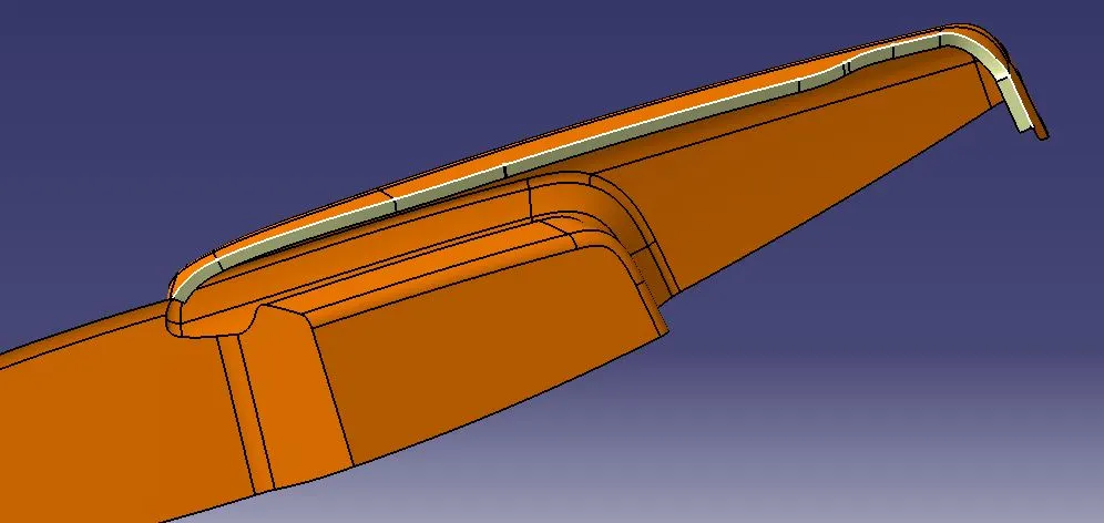
NOTE: The draft angle is determined based on the surface concerning the tooling axis:
a) If the surface seems perpendicular to the tooling axis, proceed with at least a 3-deg draft angle.
b) If the surface seems parallel to the tooling axis, proceed with a 90-degree draft angle concerning the surface.
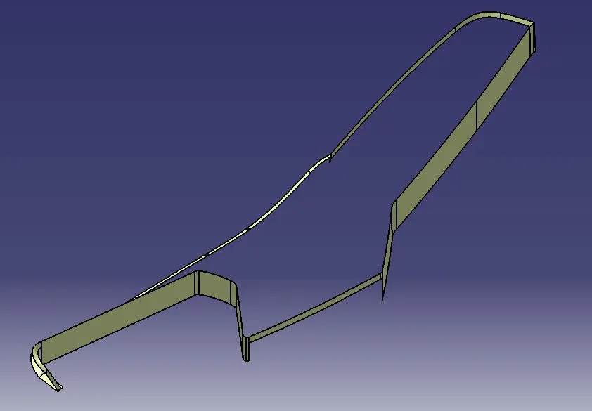
STEP-3: Extrapolated each connecting edge of the generated Class-C Surface up to a certain mm so that the surfaces intersect each other to trim it. Then, I joined the trimmed surface with the surface that formed separately using the Multi-Sections Surface command to form a complete Class-C Surface.
Part Body Creation:
STEP-1: Joined the Class-A and Class-C surfaces and trimmed them with the Class-B Surface. If it failed at the trim operation, an intersection was taken between the conjoined Class-A and Class-C surfaces with the Class-B Surface. The non-intersection area was then checked, and the Class-B Surface was extrapolated at the non-intersection edges. This process was repeated until the Closed surface formation was achieved.
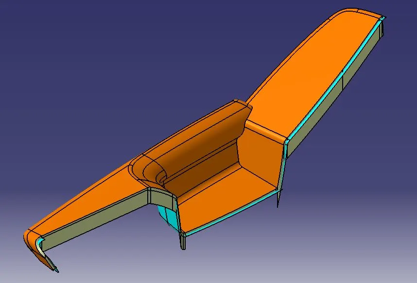
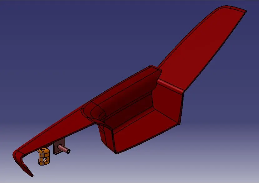
STEP-2: Finally, the Arm Rest Plastic component 3D Solid CATpart was created from the trimmed closed surface using the Close Surface command.
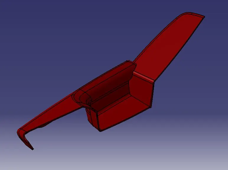
Engineering Features:
Flange and Heat Stake Creation:
STEP-1: Upon analyzing the Master Section associated with the armrest, two features had to be developed.
1) Flange attachment with Heat Stake on it which gets to fit on Upper Substrate flange.
2) The flange for the Heat Stake comes with a Lower Substrate part.
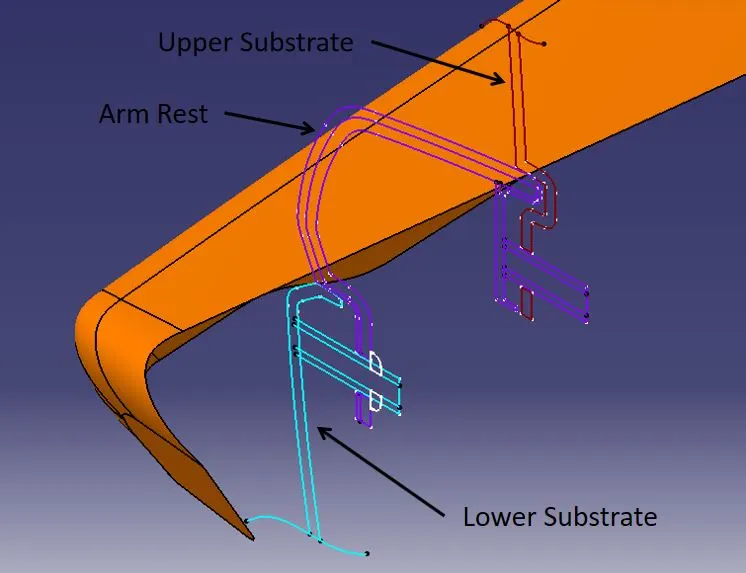
STEP-2: A sketch plane was generated referencing the master section, and certain profiles were projected onto it to design the flange using the sweep command. Several other surface operations were carried out to form the close surface. Similarly, the heat stake part was also projected from the master section and created into a solid part.
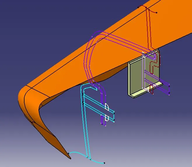
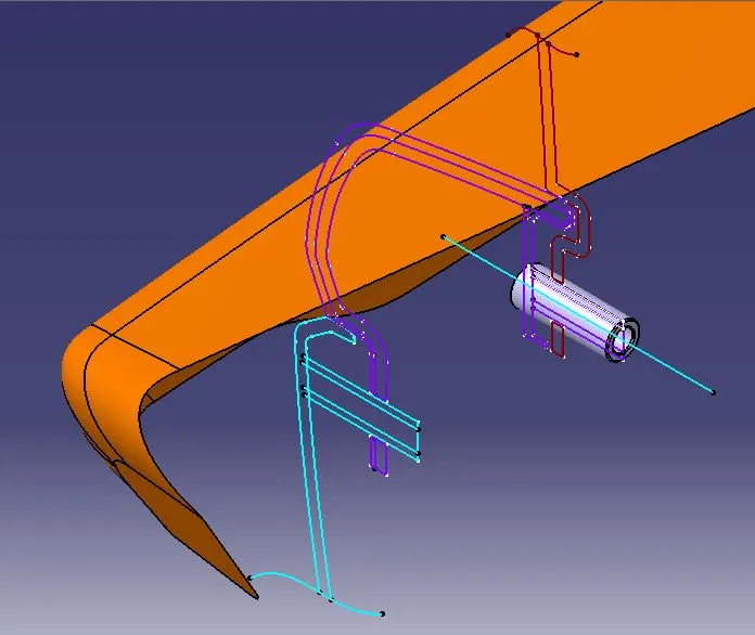
STEP-3: The same approach was followed for the next flange and provided a hole for the lower substrate heat stake. Then the 0.5 deg draft angle and the fillets were provided at the required places for the solid part.
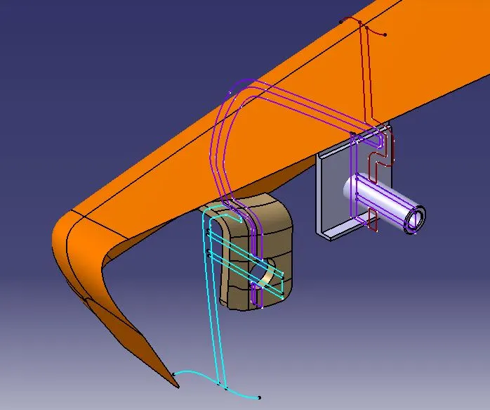
STEP-4: At last, the armrest incorporating engineering features was formed using the Boolean operations.
Part-Body Draft Analysis:
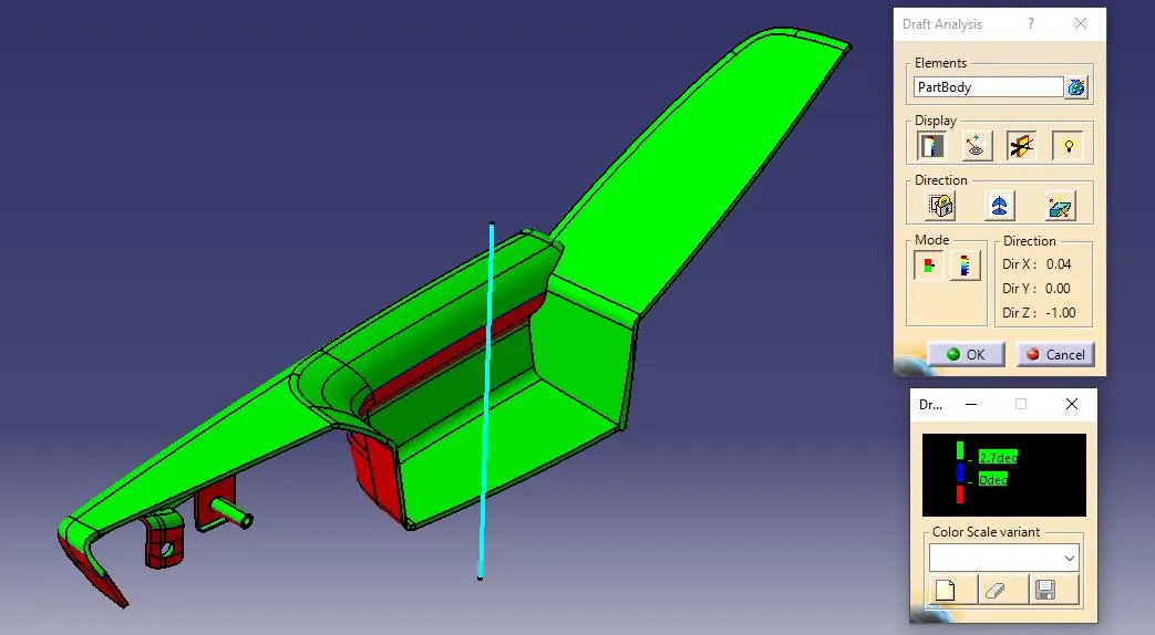
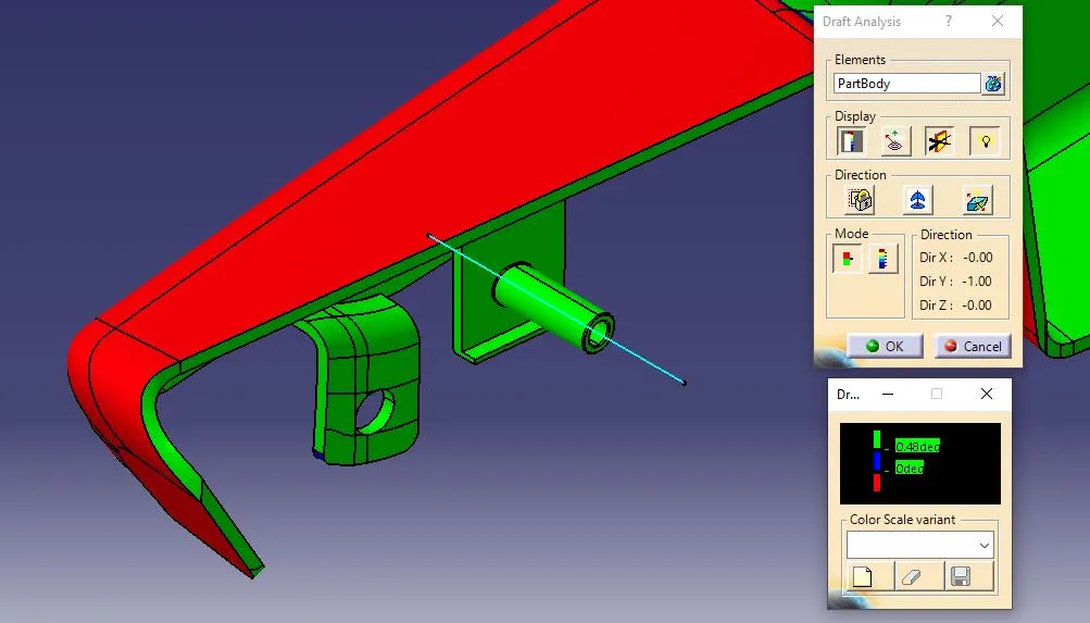
Draft analysis on the solid part resulted in green and red regions.
The tooling axis did not pass the 3-deg draft angle criteria for manufacturing the armrest component at certain sections as there is an issue in the Class-A surface itself. The Engineering features such as the heat stake and flange cleared the 0.5 deg draft angle along the side core axis direction.
B] Bottle Holder Design:
Tooling Axis Creation:
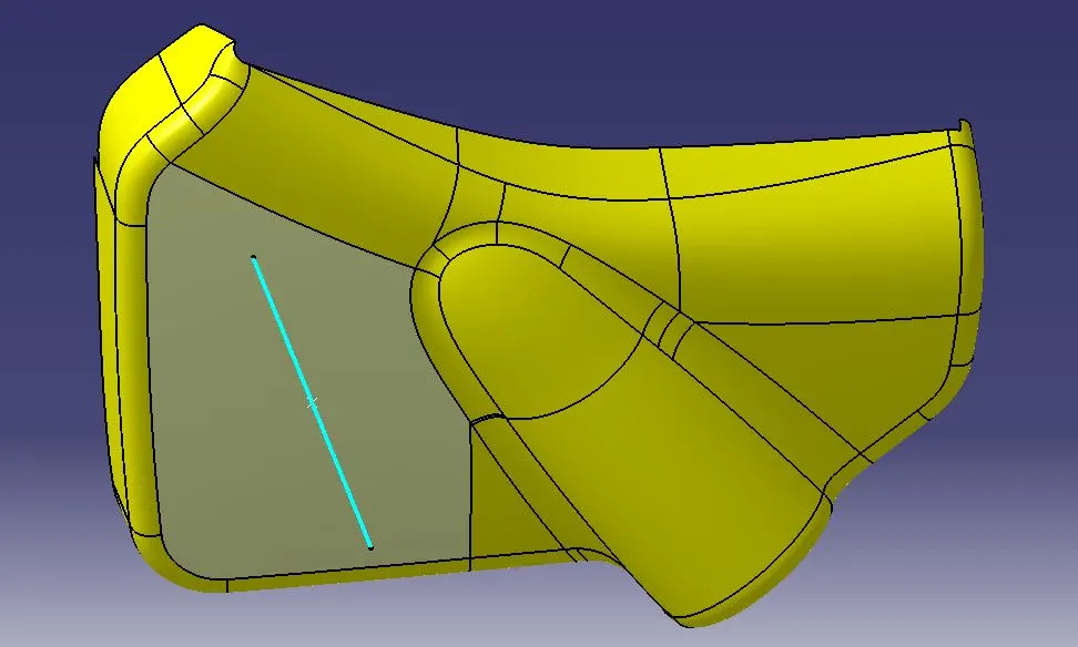
STEP-1: The tooling axis was constructed along the Y-direction by taking a point at the centre of an extracted surface from the Class-A Surface.
Class-A Surface Draft Analysis:
Before generating the part model, conducting a Class-A Surface draft analysis is important to check the manufacturing complexity and to ensure and understand the potential challenges.
The drafting possibilities are based on various axes.
X-axis: Not possible to produce.
Y-axis: Cheap and easy way to produce the component.
Z-axis: Not possible to produce.
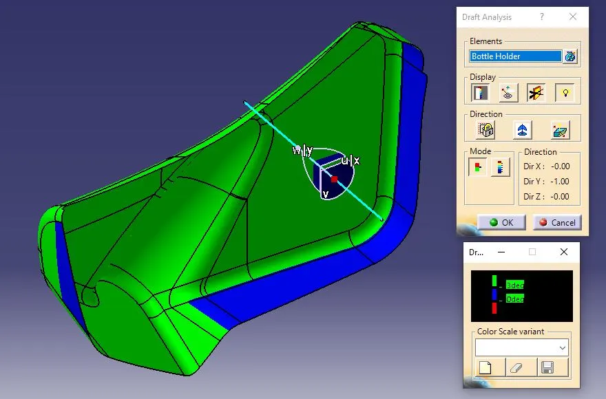
The tooling axis did not pass the 3-deg draft angle criteria for manufacturing the bottle holder component in two sections because it has a 0-deg draft. This issue was supposed to be reported to the Styling Team and they will carry out the necessary modification. Since the project's objective was to analyze the Class-A Surface and design the thickened part with B-side features, the next steps were progressed accordingly.
Class-B Surface Creation:
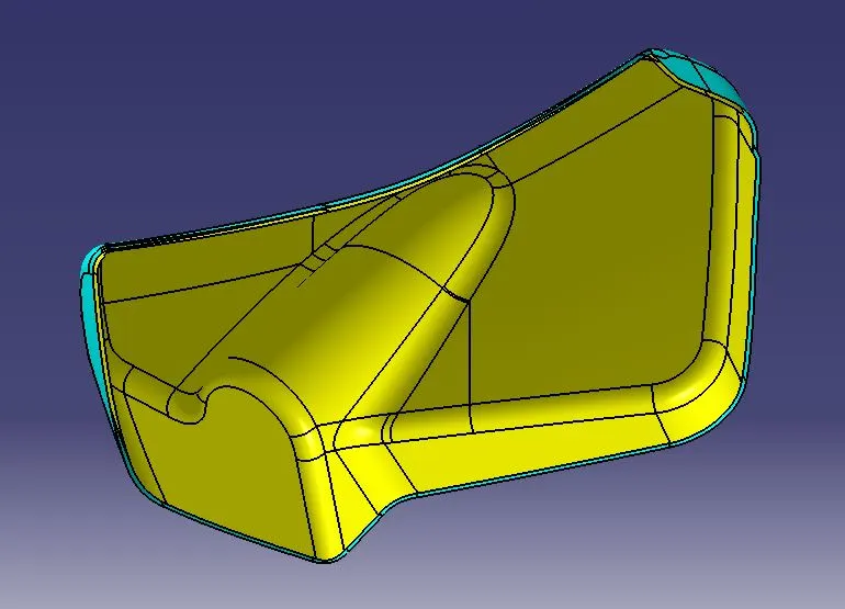
STEP-1: Offset the Class-A Surface by 2.5 mm outwards to create the Class-B Surface.
Class-C Surface Creation:
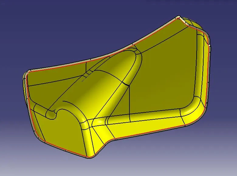
STEP-1: The total boundary of the Class-A Surface is taken and generated a surface using the sweep command across the boundary with a 90-deg draft angle about the Class-A Surface. The generated surface direction should be towards the Class-B Surface.
Part Body Creation:
STEP-1: Joined the Class-A and Class-C surfaces and trimmed them with the Class-B Surface. If it failed at the trim operation, an intersection was taken between the conjoined Class-A and Class-C surfaces with the Class-B Surface. The non-intersection area was then checked, and the Class-B Surface was extrapolated at the non-intersection edges. This process was repeated until the Closed surface formation was achieved.
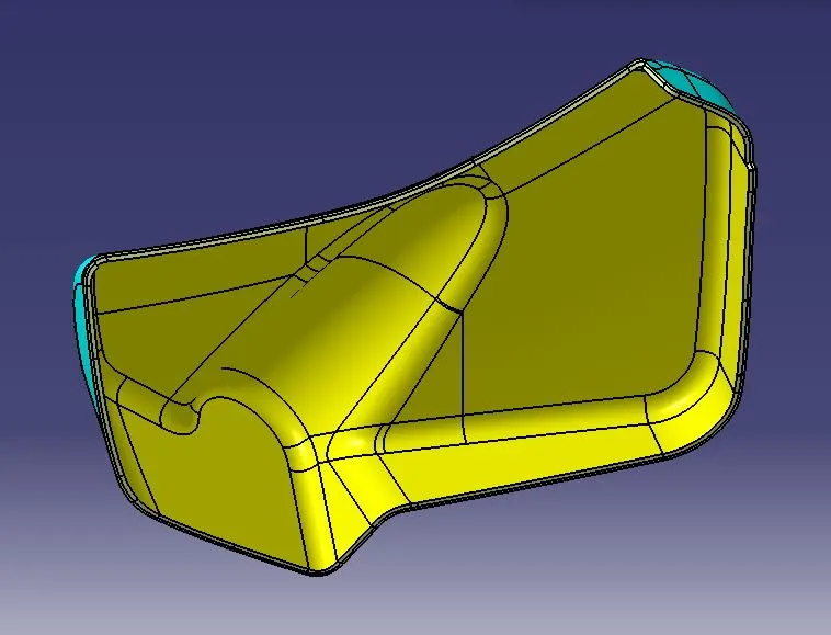
STEP-2: Finally, the Bottle Holder Plastic component 3D Solid CATpart was created from the trimmed closed surface using the Close Surface command.
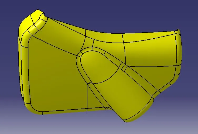
Engineering Features:
Flange Creation:
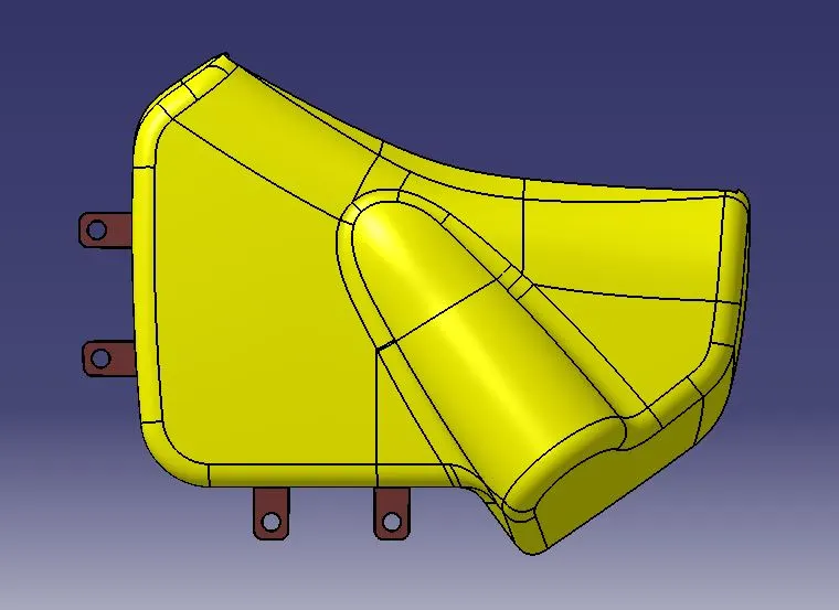
STEP-1: The flanges in the Bottle Holder are created to get fixed with the Lower Substrate part. A parallel curve is drawn from the edge of the extracted surface, and from that a surface was extruded perpendicularly to the Class-A Surface and split into two parts.
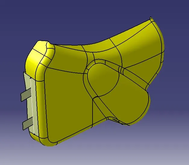
STEP-2: Those surfaces are thickened using the Thick Surface command and the hole cut is provided for the heat stakes. Then as per the design rules the 0.5 draft angle using the side core axis and the fillets are provided.
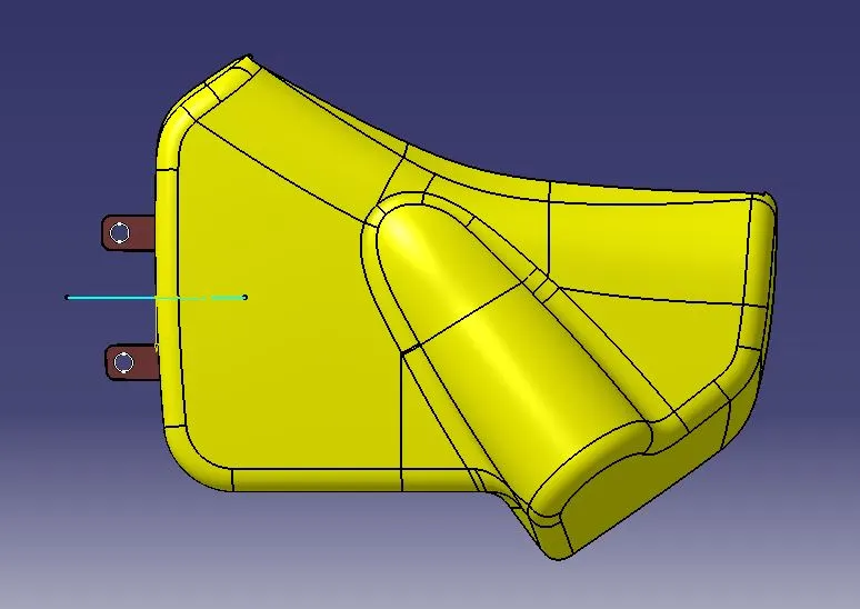
STEP-3: The same steps were followed to create the other two flanges and were merged using Boolean operations.
Part-Body Draft Analysis:
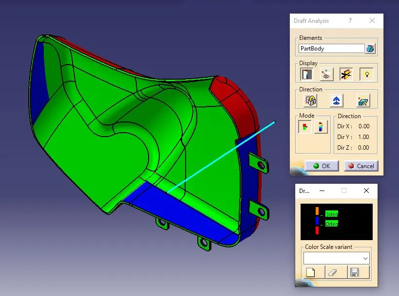
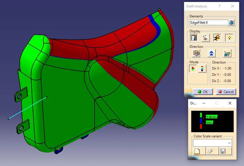
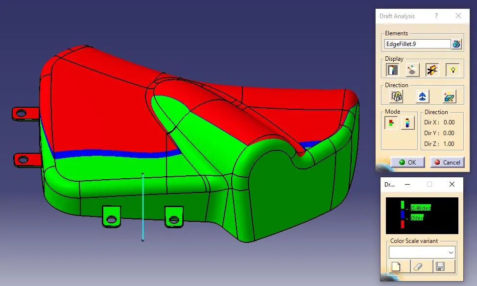
Draft analysis on the solid part resulted as below:
The tooling axis did not pass the 3-deg draft angle criteria for manufacturing the bottle holder component at certain sections as there is an issue in the Class-A surface itself. The Engineering features such as the flanges cleared the 0.5 deg draft angle along the side core axes direction.
C] Map Pocket Design:
Tooling Axis Creation:
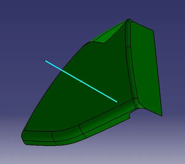
STEP-1: The tooling axis was constructed along the Y-direction by taking a point at the centre of the Class-A Surface, which was considered a dummy tooling axis.
Class-A Surface Draft Analysis:
Before generating the part model, conducting a Class-A Surface draft analysis is important to check the manufacturing complexity and to ensure and understand the potential challenges.
The drafting possibilities are based on various axes.
X-axis: Not possible to produce.
Y-axis: Cheap and easy way to produce the component.
Z-axis: Not possible to produce.
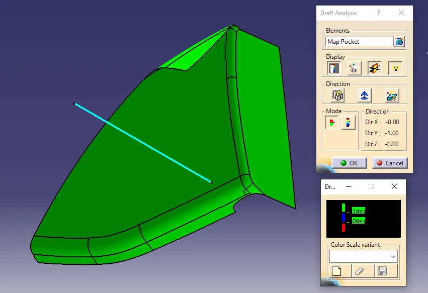
The dummy tooling axis passed the 3-deg draft angle criteria for manufacturing the bumper component. So, let's consider it as the primary tooling axis.
Class-B Surface Creation:
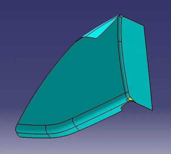
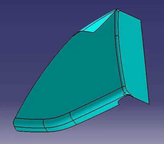
STEP-1: Offset the entire Class-A Surface by 2.5mm inwards and the surface failed to generate is created by using the Multi-Sections Surface command. Both surfaces are joined to create the Class-B Surface.
Class-C Surface Creation:
STEP-1: Boundaries are taken with limits one by one on Class-A Surface as shown in the below image. Then, the surface using the sweep command was generated across each boundary with a 3-deg draft angle along the tooling axis as the draft direction.
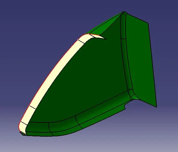
STEP-2: Again boundaries are taken with limits one by one on the Class-A Surface as shown in the below image. Then, the surface using the sweep command was generated across each boundary with a 90-degree draft angle concerning the surface. The generated surface direction should be towards the Class-B Surface.
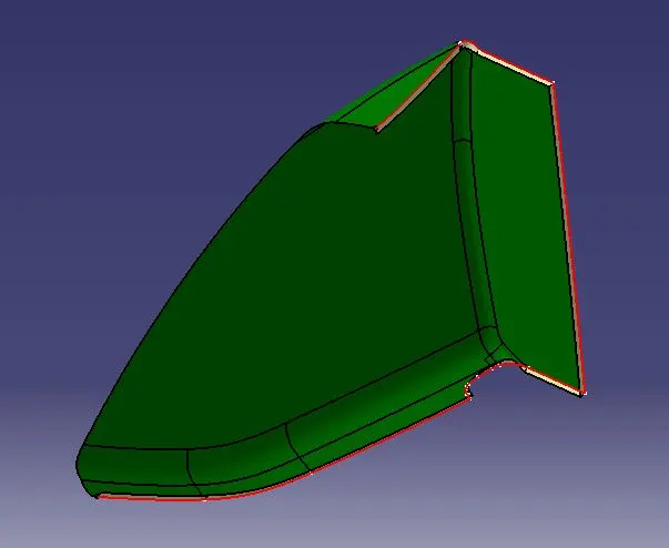
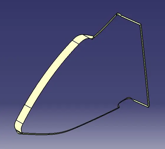
STEP-3: Extrapolated each connecting edge of the generated Class-C Surface up to a certain mm so that the surfaces intersect each other to trim it. Then, I joined the trimmed surface with the surface that formed separately using the Multi-Sections Surface command to form a complete Class-C Surface.
Part Body Creation:
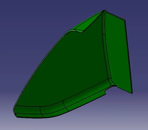
STEP-1: Joined the Class-A and Class-C surfaces and trimmed them with the Class-B Surface. If it failed at the trim operation, an intersection was taken between the conjoined Class-A and Class-C surfaces with the Class-B Surface. The non-intersection area was then checked, and the Class-B Surface was extrapolated at the non-intersection edges. This process was repeated until the Closed surface formation was achieved.
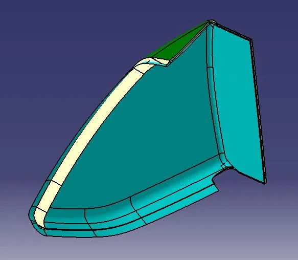
STEP-2: Finally, the Map Pocket Plastic component 3D Solid CATpart was created from the trimmed closed surface using the Close Surface command.
Engineering Features:
Flange Creation:
STEP-1: Upon analyzing the Master Section associated with the map pocket, two different flanges had to be developed.
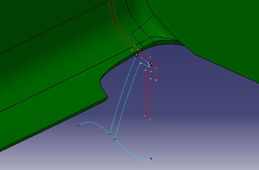
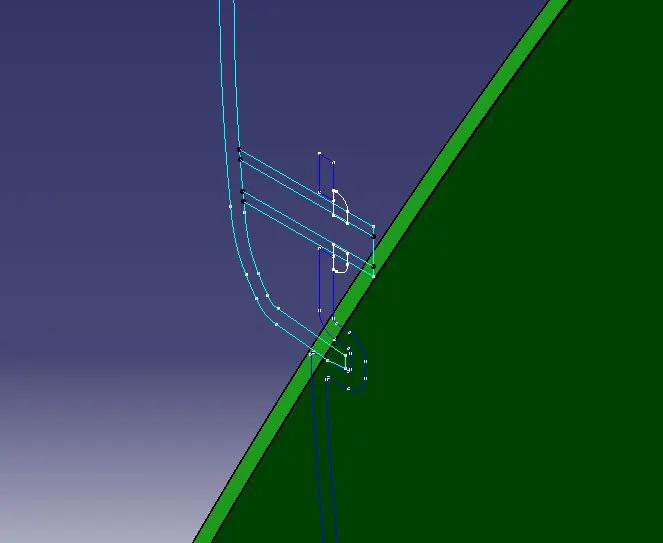
STEP-2: A sketch plane was generated referencing the master section, and certain profiles were projected onto it to design the flange using the sweep command. Several other surface operations were carried out to form the close surface. On the solid part, a hole cutout was made for the heat stake.
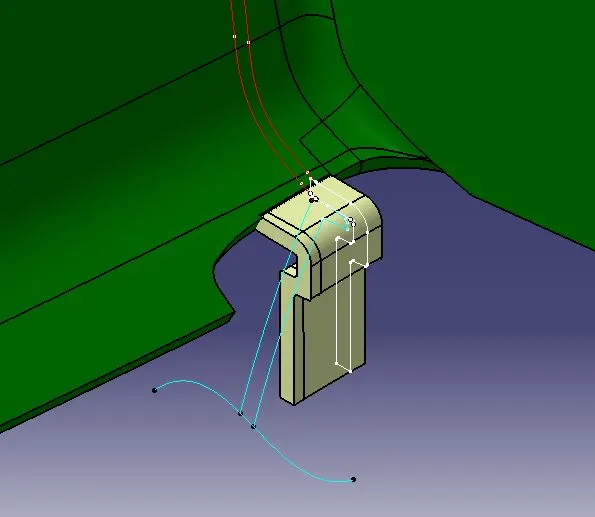
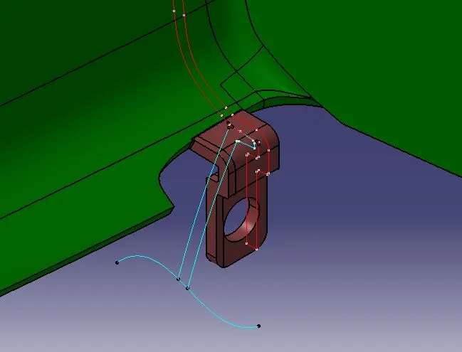
STEP-3: The same approach was followed again for the other flange and the fillets were provided for all the flanges.
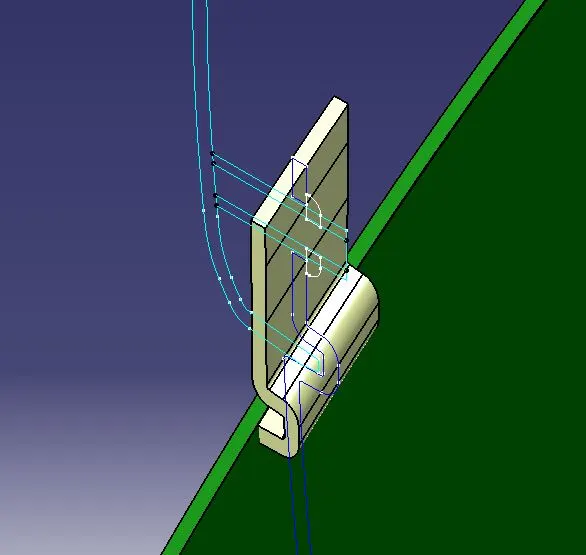
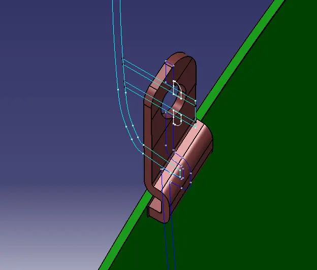
STEP-4: At last, all three flanges were merged into the map pocket main part using the Boolean operations.
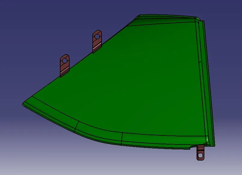
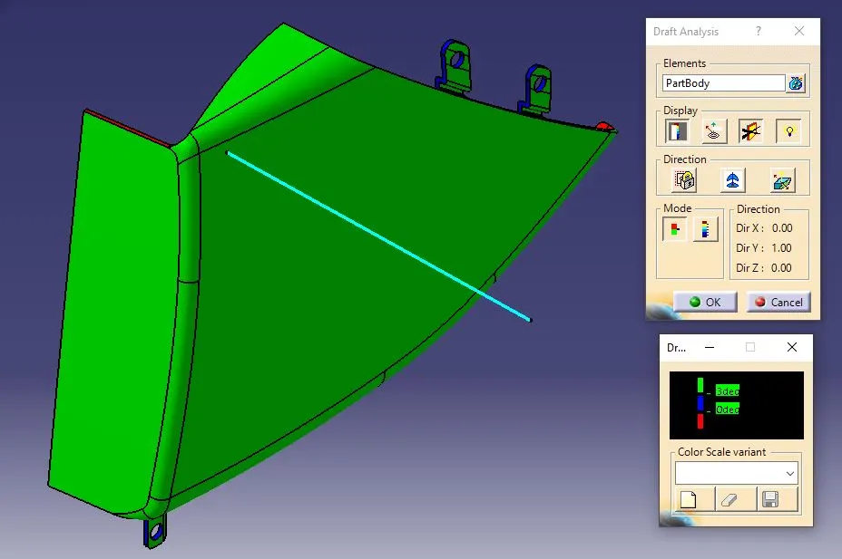
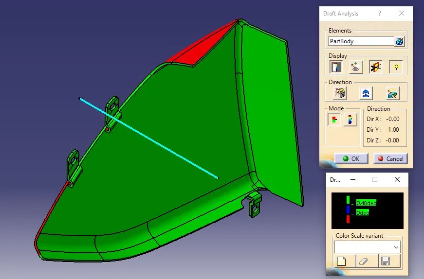
Part-Body Draft Analysis:
Draft analysis on the solid part resulted in a green region stating that the part is toolable or produceable by the moulding machine with a 3-deg draft angle for the main part and 0.5 deg for flanges.
D] Lower Substrate Design:
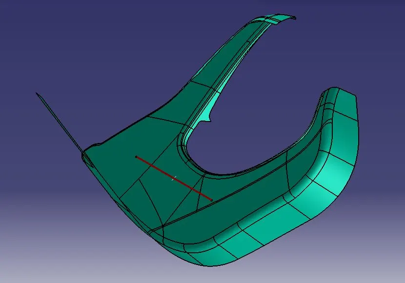
Tooling Axis Creation:
STEP-1: The tooling axis was constructed along the Y-direction by taking a point at the centre of an extracted surface from the Class-A Surface, which was considered a dummy tooling axis.
Class-A Surface Draft Analysis:
Before generating the part model, conducting a Class-A Surface draft analysis is important to check the manufacturing complexity and to ensure and understand the potential challenges.
The drafting possibilities are based on various axes.
X-axis: Not possible to produce.
Y-axis: Cheap and easy way to produce the component.
Z-axis: Not possible to produce.
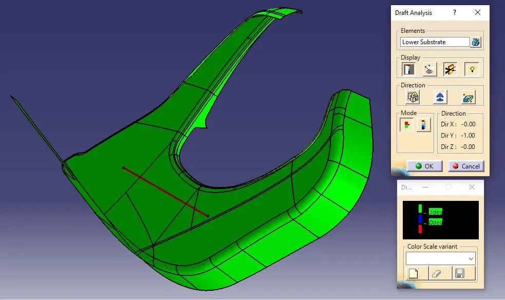
The dummy tooling axis passed the 3-deg draft angle criteria for manufacturing the bumper component. So, let's consider it as the primary tooling axis.
Class-B Surface Creation:
STEP-1: Offset the Class-A Surface by 2.5 mm outwards to create the Class-B Surface.
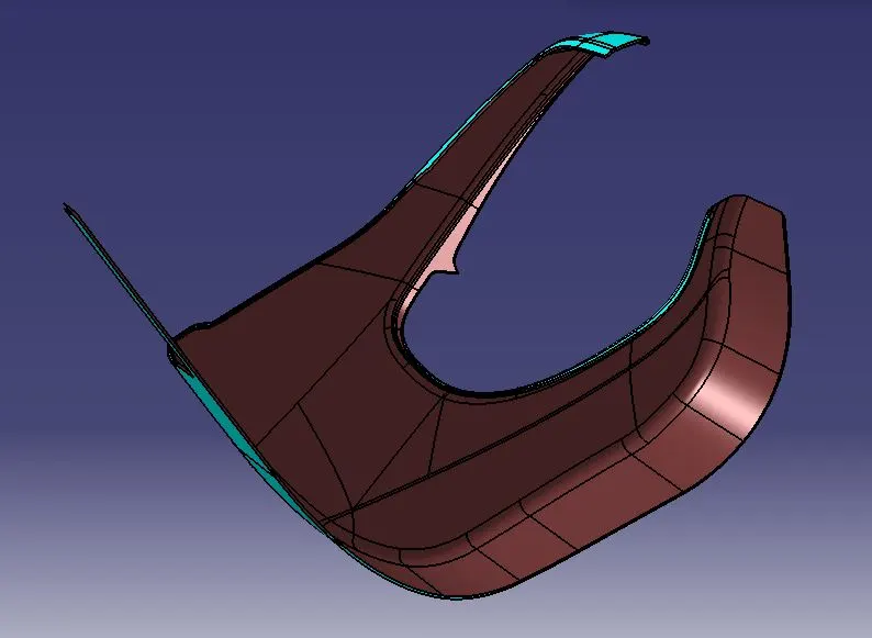
Class-C Surface Creation:
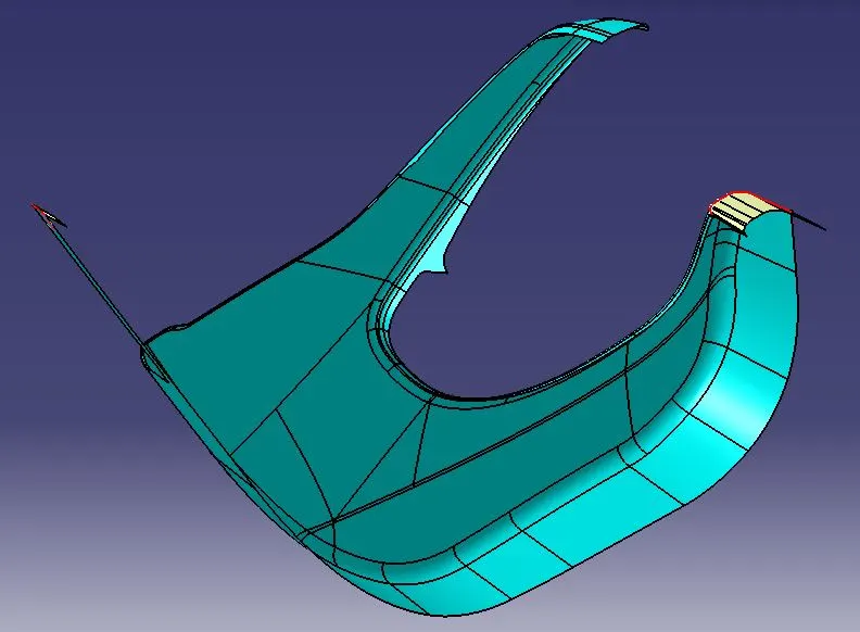
STEP-1: Boundaries are taken with limits one by one on Class-A Surface as shown in the below image. Then, the surface using the sweep command was generated across each boundary with a 3-deg draft angle along the tooling axis as the draft direction.
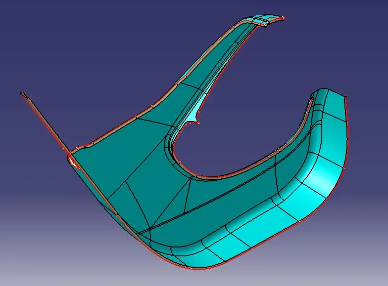
STEP-2: Again boundaries are taken with limits one by one on the Class-A Surface as shown in the below image. Then, the surface using the sweep command was generated across each boundary with a 90-degree draft angle concerning the surface. The generated surface direction should be towards the Class-B Surface.
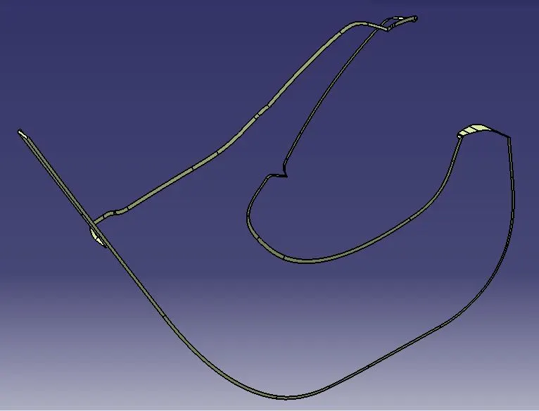
STEP-3: Extrapolated each connecting edge of the generated Class-C Surface up to a certain mm so that the surfaces intersect each other to trim it to form a complete Class-C Surface.
Part Body Creation:
STEP-1: Joined the Class-A and Class-C surfaces and trimmed them with the Class-B Surface. If it failed at the trim operation, an intersection was taken between the conjoined Class-A and Class-C surfaces with the Class-B Surface. The non-intersection area was then checked, and the Class-B Surface was extrapolated at the non-intersection edges. This process was repeated until the Closed surface formation was achieved.
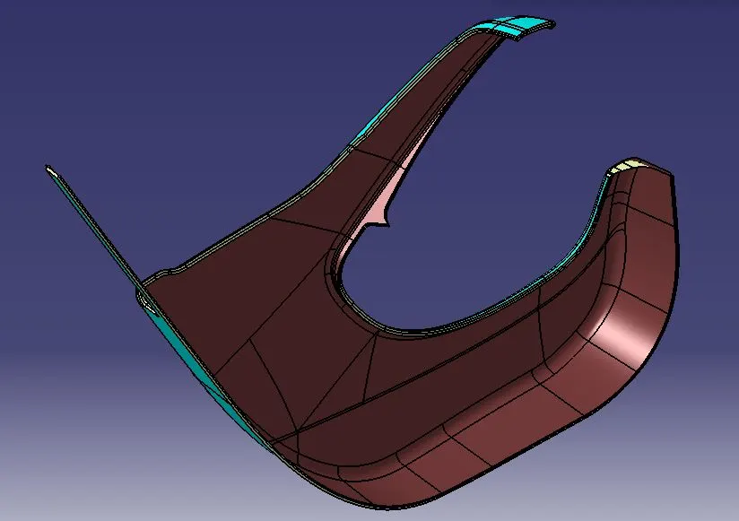
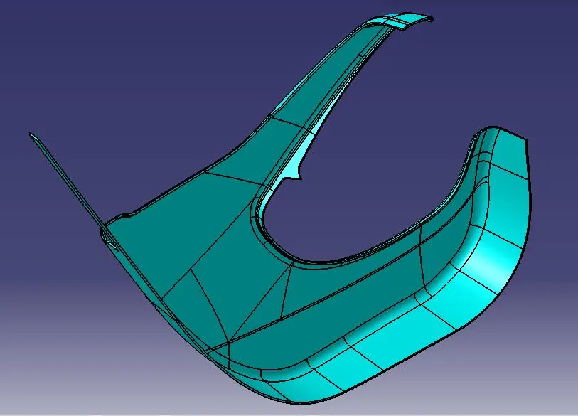
STEP-2: Finally, the Lower Substrate Plastic component 3D Solid CATpart was created from the trimmed closed surface using the Close Surface command.
Engineering Features:
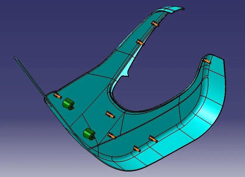
Heat Stakes Creation:
STEP-1: After analyzing the Master Section associated with the lower substrate, heat stakes were required to be created at two locations: one for the armrest and another for the map pocket. Additionally, a few heat stakes were created to fix with the bottle holder.
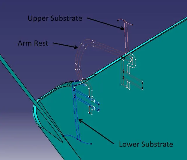
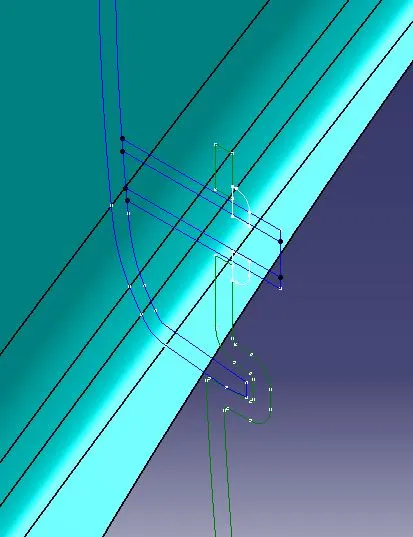
STEP-2: A sketch plane was generated referencing the master section, and the heat stake profiles were projected onto it to design it as a solid part. The supporting part was created and both parts were merged. Then as per the design rules - 0.5 draft angle, chamfer and edge fillets were provided.
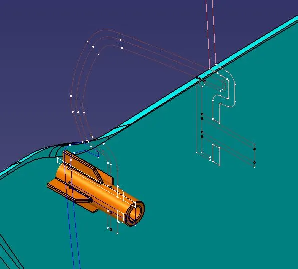
STEP-3: The required number of heat stakes was created by duplicating them and positioning them at the proper locations.
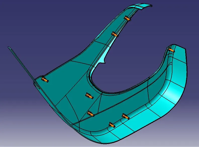
Dog House Creation:
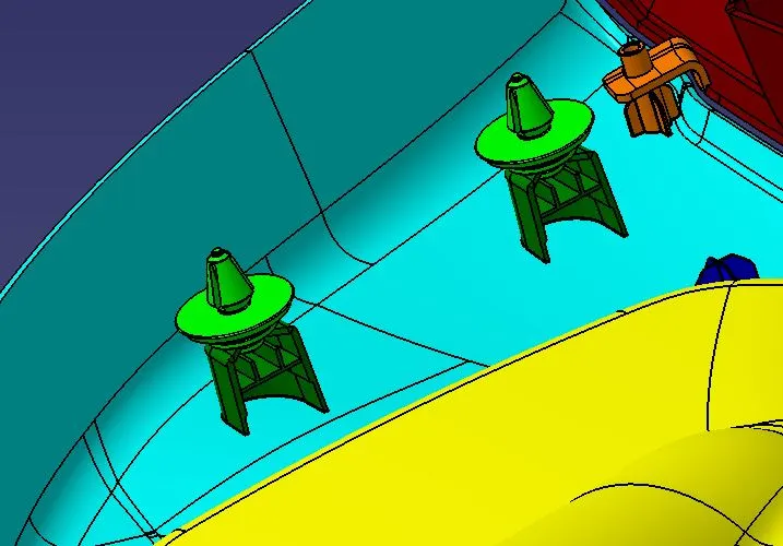
STEP-1: The dog houses were established on the lower substrate part to accommodate the placement of push pins for the assembly of the door panel. The dog houses were designed according to the provided dimensions by following the design guidelines.
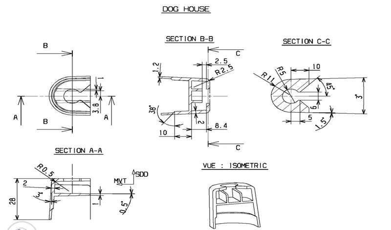
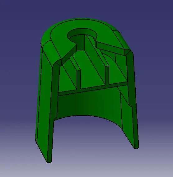
STEP-2: The required number of dog houses was created by duplicating them and positioning them at the proper locations.
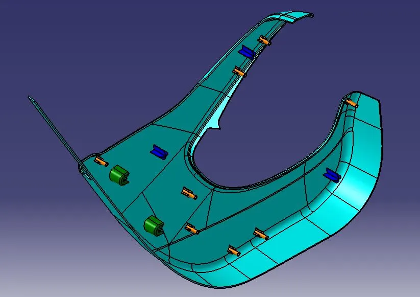
Locators Creation:
STEP-1: The locators were designed and placed on the lower substrate part at the desired locations.
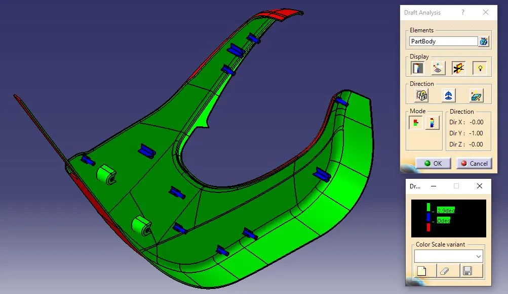
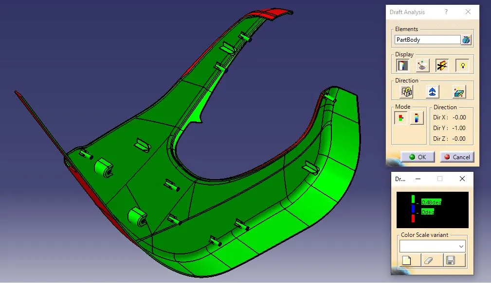
Part-Body Draft Analysis:
Draft analysis on the solid part resulted in a green region stating that the part is toolable or produceable by the moulding machine with a 3-deg draft angle for the main part and 0.5 deg for engineering features.
Final Assembly of Door Trim Panel:
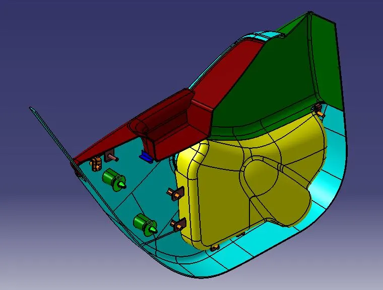
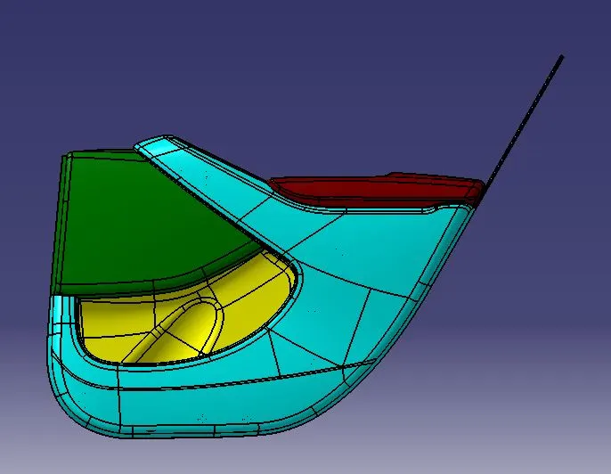
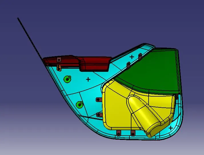
STEP-1: All four parts of the door trim panel were imported and the push pins were constrained with the dog houses perfectly for the door assemblement in a single CAT product file.
Various Views of Door Trim Panel:
Isometric View:
Front View:
Back View:
Conclusion:
Thus, the Door Trim Panel Plastic 3D component was designed for proper thickness using master sections reference with all engineering features in Catia software by following the design guidelines and standards. Furthermore, engineering features like heat stakes and push pins were created in an effective way to attach the parts firmly.