Week 12- Final project
AIM:
To design and develop vehicle interior door trim using Catia V5 with a given class A surface along with a Master section. Also, create the Side Attachment features as per the design rules.
OBJECTIVES:
- Create a sketch by using the Positioned sketch
- All the sketches should be Iso-Constrained
- Ensured Proper feature Tree Structure
- Geometrical sets should have a proper name based on the sketches present inside of it
- To create a thickened part using the master section for reference
- To create the mounting features as per design guidelines in the industry and with master sections
- Creation of Draft analysis & Tooling analysis
INTRODUCTION:
The door panel is the interface between the interior of the car and the inner workings of the door. Generally, the door panel is divided into parts for easy designing like an armrest, map pocket, and the lower substrate. This is one of the toughest requirements among the interior parts of the car. This should be designed to withstand the load while being less than 2mm in thickness and also to protect the occupants during collisions.
The door currently has an inner full-width panel consisting of electronic windows, a central locking system, and speakers. These panels typically consist of a foamed core covered with either textiles or plastics.
ASSEMBLY WORKBENCH:
The assembly workbenches use constraints and expressions to create relationships between the objects in the model and to mathematically tie the objects in place.
The components are brought together and assembled in the Assembly Design workbench by applying suitable parametric assembly constraints to them. The assembly constraints allow you to restrict the degrees of freedom of components on their respective work positions. The assembly files in CATIA are called Product Files.
TOP - DOWN ASSEMBLY APPROACH:
The top-down assembly approach is a method of creating and designing the geometry within an assembly. This is also called “in-context design” because everything is created in the context of an assembly.
BOTTOM - UP ASSEMBLY APPROACH:
The bottom-up assembly approach is a method of creating and designing every individual part separately. In the bottom-up approach, all the parts need to be created correctly with all the right dimensions to ensure they fit properly.
CREATION OF TOOLING AXIS
Step 1: Insert a geometrical set. Extract the base surface and create a point at its center using a point-on-surface option from the point tool. Look for a suitable axis to create a tooling axis so that all faces have clear tooling.
Step 2: Create an axis system without the current option ticked at the above point. Create a position sketch with the zy plane from the axis system and the above point as a reference point.
Step 3: Use the intersect 3d objects option from the project tool to create 2 lines by selecting a suitable plane(zy). Now create 2 lines that coincide with lines on both sides of the projection point. Create a line using the bisect option. Align the line in the required axis direction. This is our Y tooling axis.
Step 4: To create a tooling axis about the x direction, create a position sketch with the xz plane as the reference plane and the projection point as the first point we created. Use the cut section tool and create an intersection using the projection tool. Now create a line that coincides with this line.
Step 5: Draw a line from the origin in the horizontal direction and create an angle constraint of 5 degrees. Use the bisect option to create a line between the above lines. This is our X tooling axis.
Step 6: Create a new line using the bisect option between the X tooling and Y tooling line. this is our required Tooling Axis, Name this as the tooling axis and publish it.
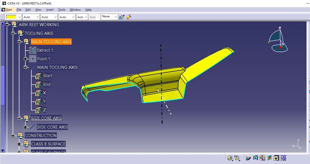
PROCEDURE FOR DRAFT ANALYSIS:
1)Once the tooling axis is created, publish it and the component using the Publication from tool option.
2)Insert the Feature draft analysis option from the inserts toolbar
3) Change the view option to customize view parameters and click on the material option under shading.
4) Now click on the axis option from Draft Analysis tools, align it with the tooling axis, and click on the lock option to lock it.
5) Change the draft angle value to 3 degrees. Click on quick analysis mode to display features according to the given color scale. Check from all views to ensure the draft analysis is cleared.
6) Since the created tooling axis does not clear the draft analysis at the created axis click on the lock axis button to unlock it. Now rotate the tooling axis by left-clicking on the top round portion of the axis system. Rotate the axis till maximum clearance is obtained. Now right-click on the axis and click lock current axis
7) Create a line using the initial axis origin and this axis using the point and direction (using compass direction) option. This is our required tooling axis.
8) Now if we check for draft analysis, we can observe that the ribbed area has not yet cleared draft analysis. Hence, we need to create a side core tooling axis. To do this, create a line using the point and direction option with the Y direction.
9) Repeat steps 1 to 5 to ensure the remaining portion which was not cleared using the Tooling axis has been cleared using this axis.
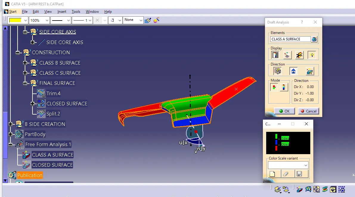
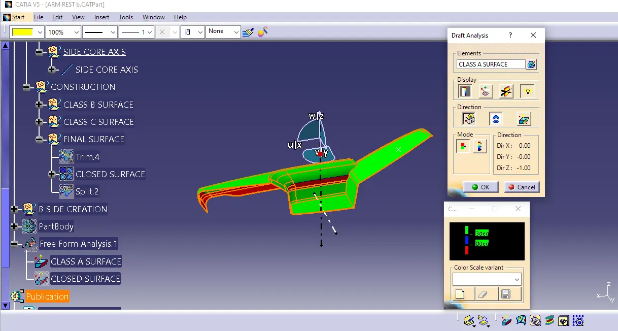
Similarly, a tooling axis uses the same procedures for all other components.
Tooling axis for lower substrate
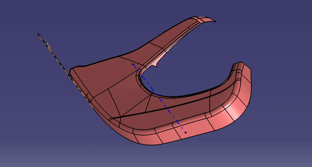
Tooling axis for Map pocket
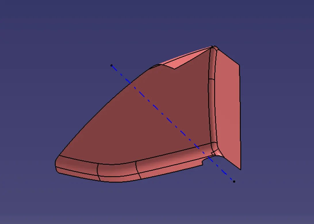
Tooling axis for BOTTLE HOLDER:
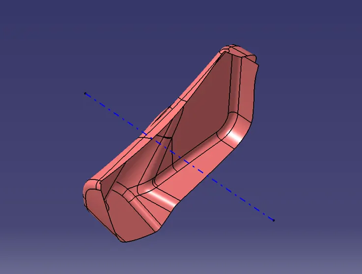
This would lead to ejection problems during the molding process. Hence the class A surface has to be modified to meet draft requirements Hence we have created a tooling axis for all components.
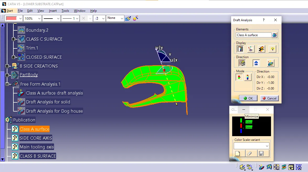
Draft Analysis for given class A surface for Lower substrate:
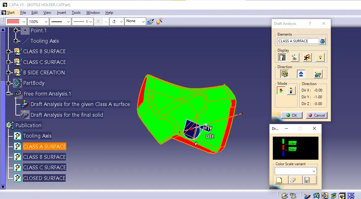
Draft Analysis for given class A surface for Bottle holder:
Draft Analysis for given class A surface for Map Pocket:
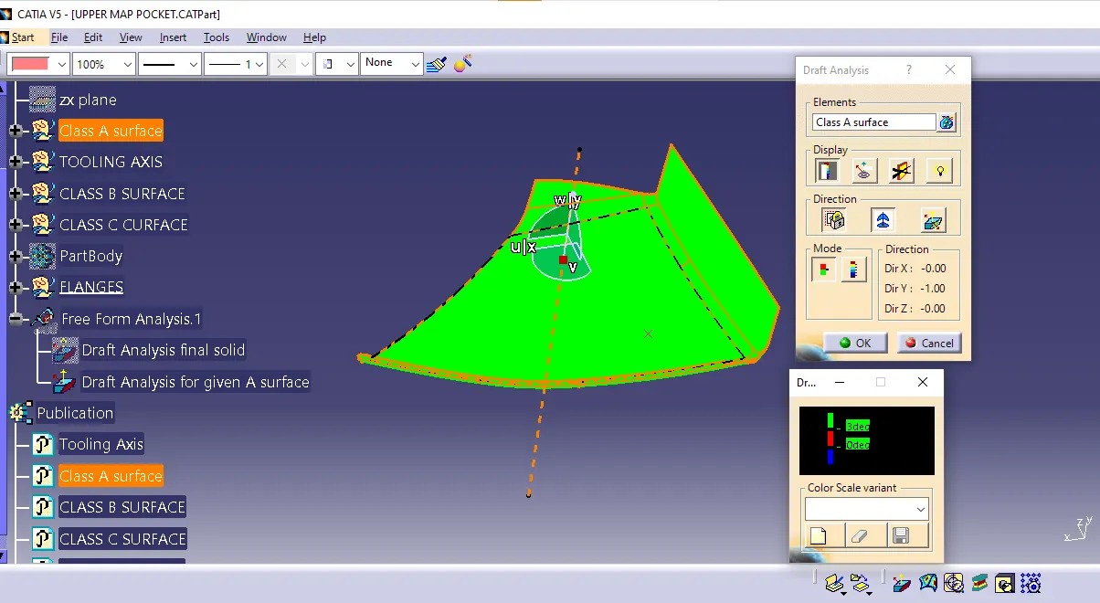
2) Creation of class B surface:
Procedure to create class B surface for the MAP POCKET.
Step 1: Use the offset tool with a distance value of 2.5mm to create the offset of class A surface.
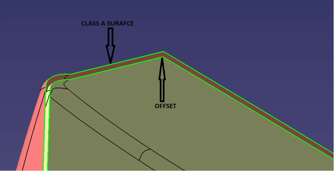
Step 2: After offsetting, an extrapolate tool was used to extend all the edges of this surface. This is done to ensure that the parting line comes at the B surface.
Step 3: In areas where extrapolation was not possible (Fillet or cusped surfaces) multi-section surface option was used.
Step 4: Join all the extrapolated surface and multi-section surfaces to obtain a single surface.
Hence the class B surface was created for MAP POCKET.
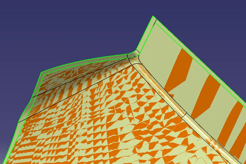
Similarly, a class B surface was created for other components.
Class B surface of ARMREST:
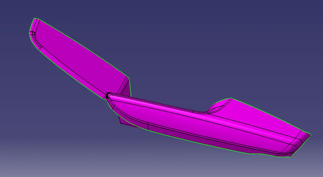
Class B surface of LOWER SUBSTRATE:
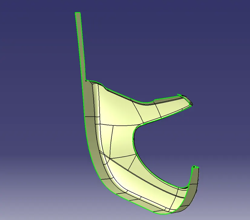
Class B surface of BOTTLE HOLDER:
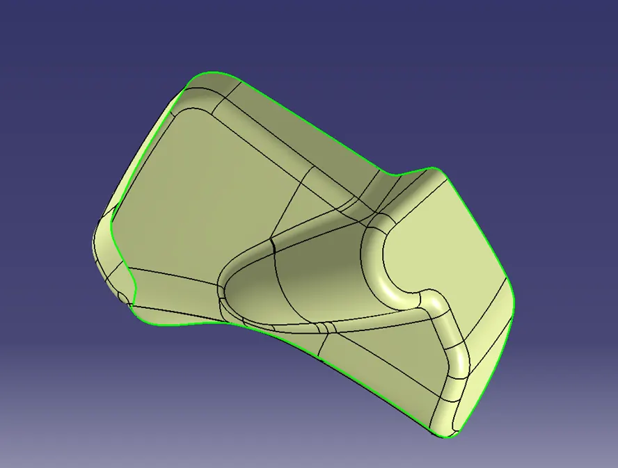
Hence class B surfaces for all components were created.
3) Creation of Class C surface:
Procedure for creation of class C surface for Upper map pocket
Step 1: Use the sweep command to create a new surface at an angle concerning the surface. This angle is dependent on a draft angle for free edges and usually 90 degrees for mating surfaces.
Step 2: In areas where sweep is not possible, use Multi section surface to create a new surface.
Step 3: Join all surfaces to obtain a C surface.
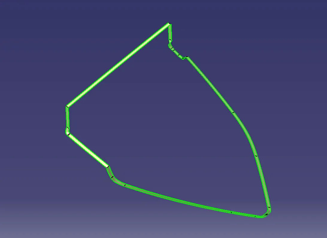
Hence C surface was obtained for MAP POCKET
Similarly, C surfaces were obtained for all other components.
Class C surface for ARMREST:
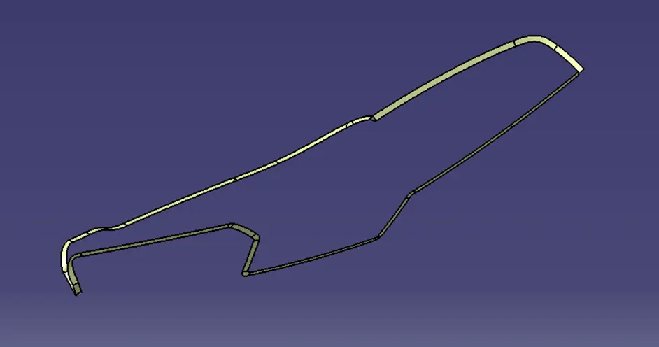
Class C surface for LOWER SUBSTRATE:
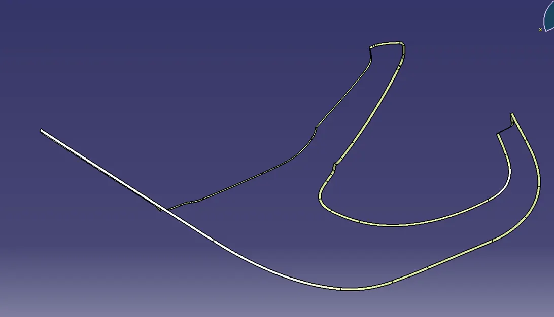
Hence class C was created for all components.
4) Creation of closed body:
Procedure for creation of closed body for lower map pocket.
Step 1: Use the trim or join option to join Class A and Class C.
Step 2: Use the trim option to join the above trim with class B
Hence, we have obtained a closed body for BOTTLE HOLDER.
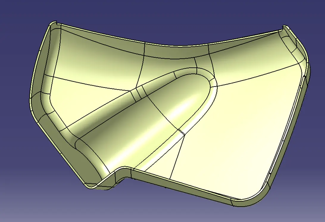
Similarly closed body was obtained for all other parts
Closed body for MAP POCKET:
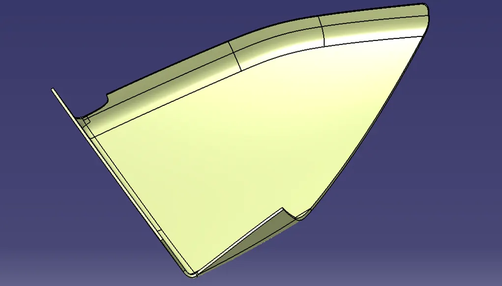
Closed body for LOWER SUBSTRATE
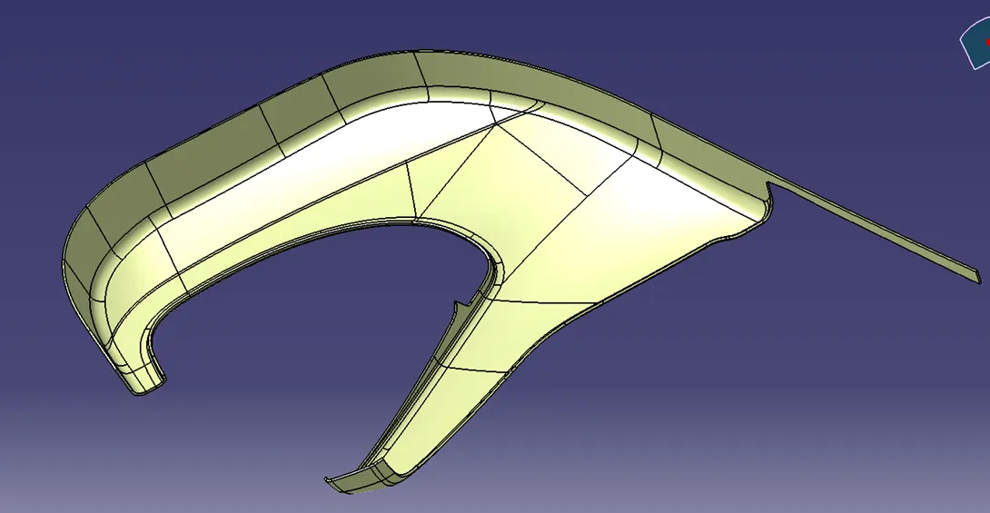
Closed body for ARMREST
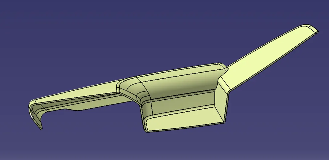
Hence, we have created closed bodies for all parts and thus we have created solid bodies from them.
Attachment of flanges using given master sections.
Procedure to create FLANGES and HEAR STAKES for Armrest from given master sections.
Step 1: Use multiple extracts to obtain the required guide curve and sweep profile for the flange top surface.
Step 2: Use the sweep option to create a surface from below obtained multiple extracts.
Step 3: Use extrapolate to extend the surface according to the master section and create a solid body in a new body. Create holes and flat surfaces for heat stake.
Step 4: Heat stake was created from padding a sketch created from a point obtained from the master section.
Step 5: Stake support was created using padding the multiple extracts from the master section and thickening it.
5) Draft Analysis:
Procedure to check Draft analysis for the Lower substrate.
1)Once the tooling axis is created, publish it and the component using the Publication from tool option.
2)Insert the Feature draft analysis option from the inserts toolbar
3) Change the view option to customize view parameters and click on the material option under shading.
4) Now click on the axis option from Draft Analysis tools, align it with the tooling axis, and click on the lock option to lock it.
5) Change the draft angle value to 3 degrees. Click on quick analysis mode to display features according to the given color scale. Check from all views to ensure the draft analysis is cleared. Click ok to complete the Draft analysis mode.
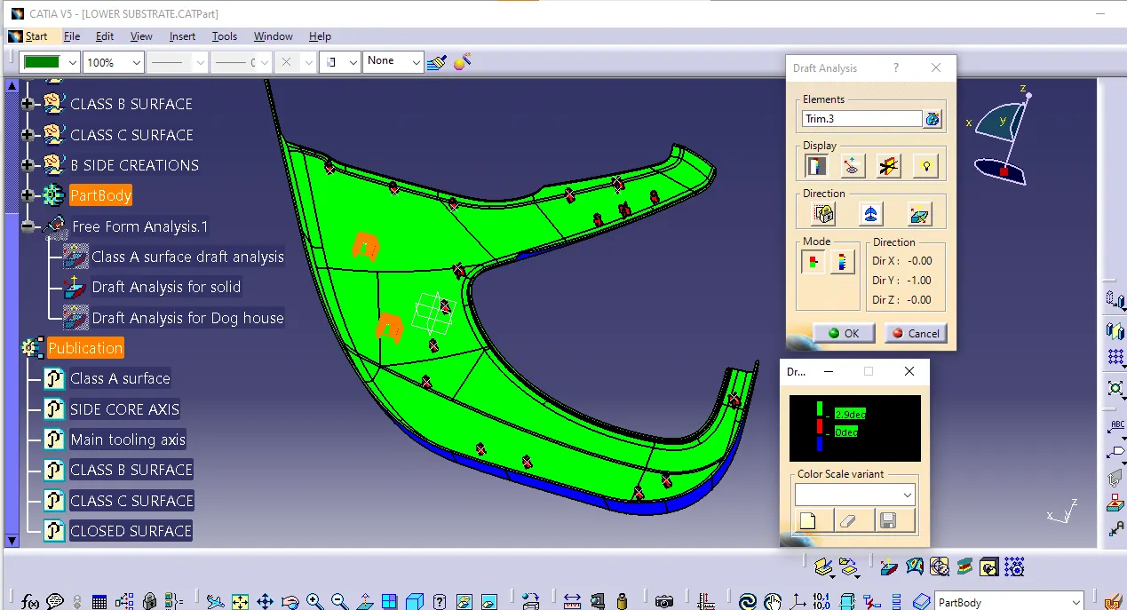
Draft Analysis for ARMREST:
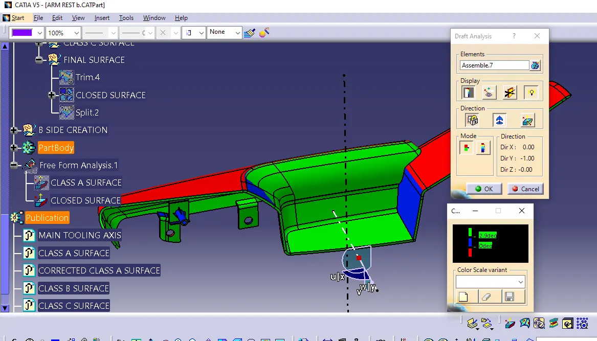
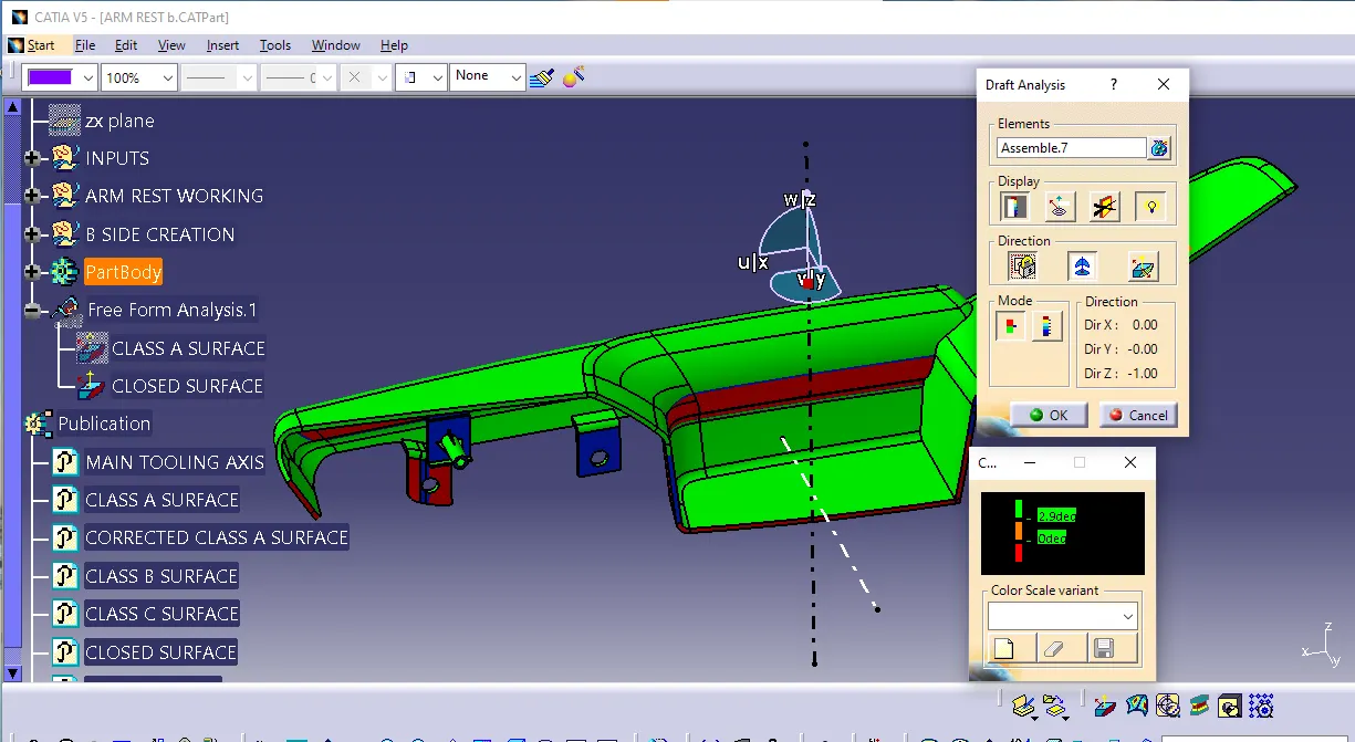
Draft analysis for MAP POCKET:
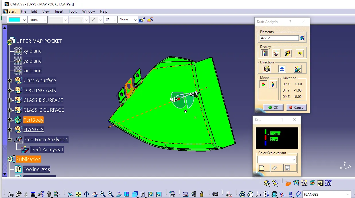
Draft analysis for BOTTLE HOLDER:
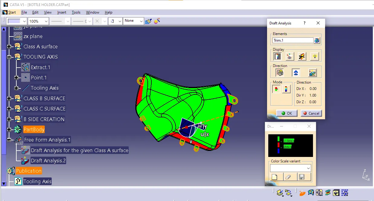
Final MAP POCKET:
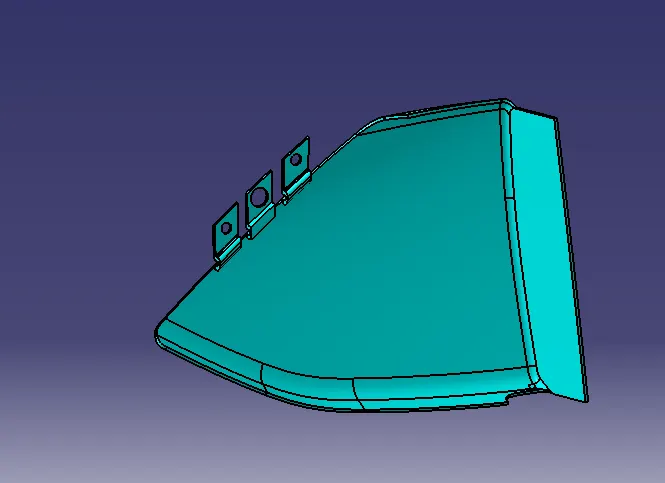
Final ARMREST:
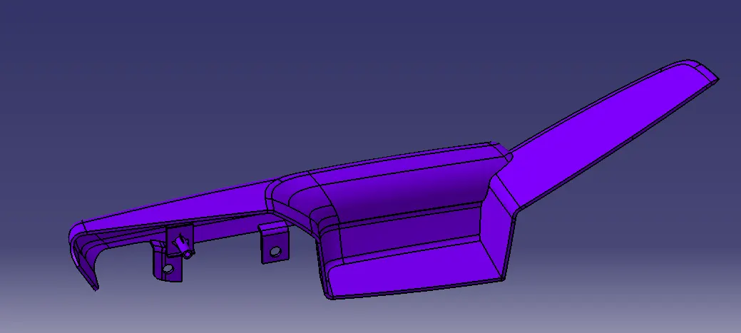
Final BOTTLE HOLDER:
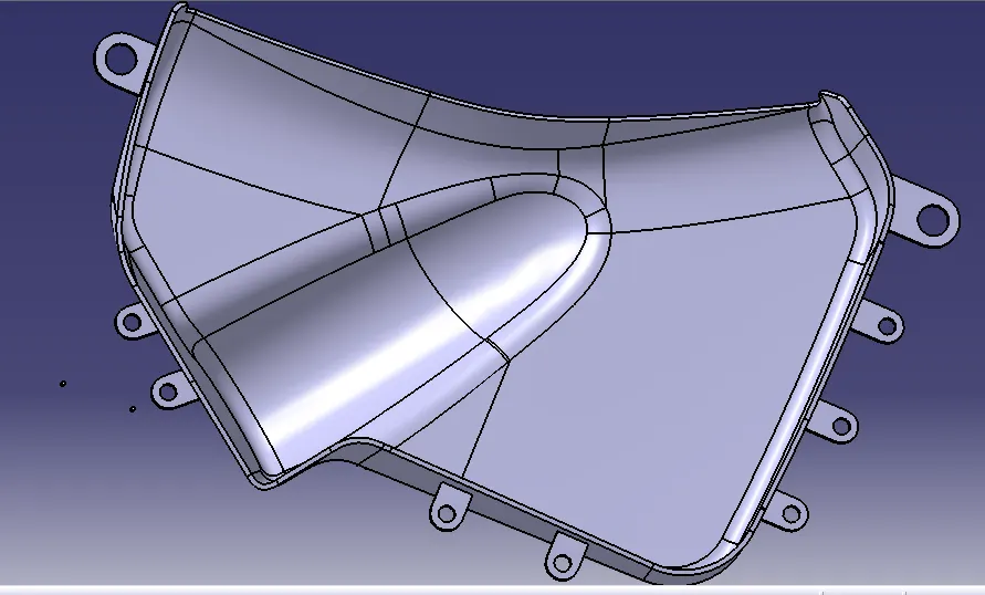
Final LOWER SUBSTRATE:
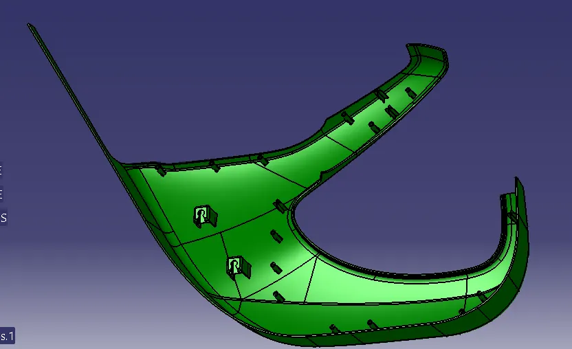
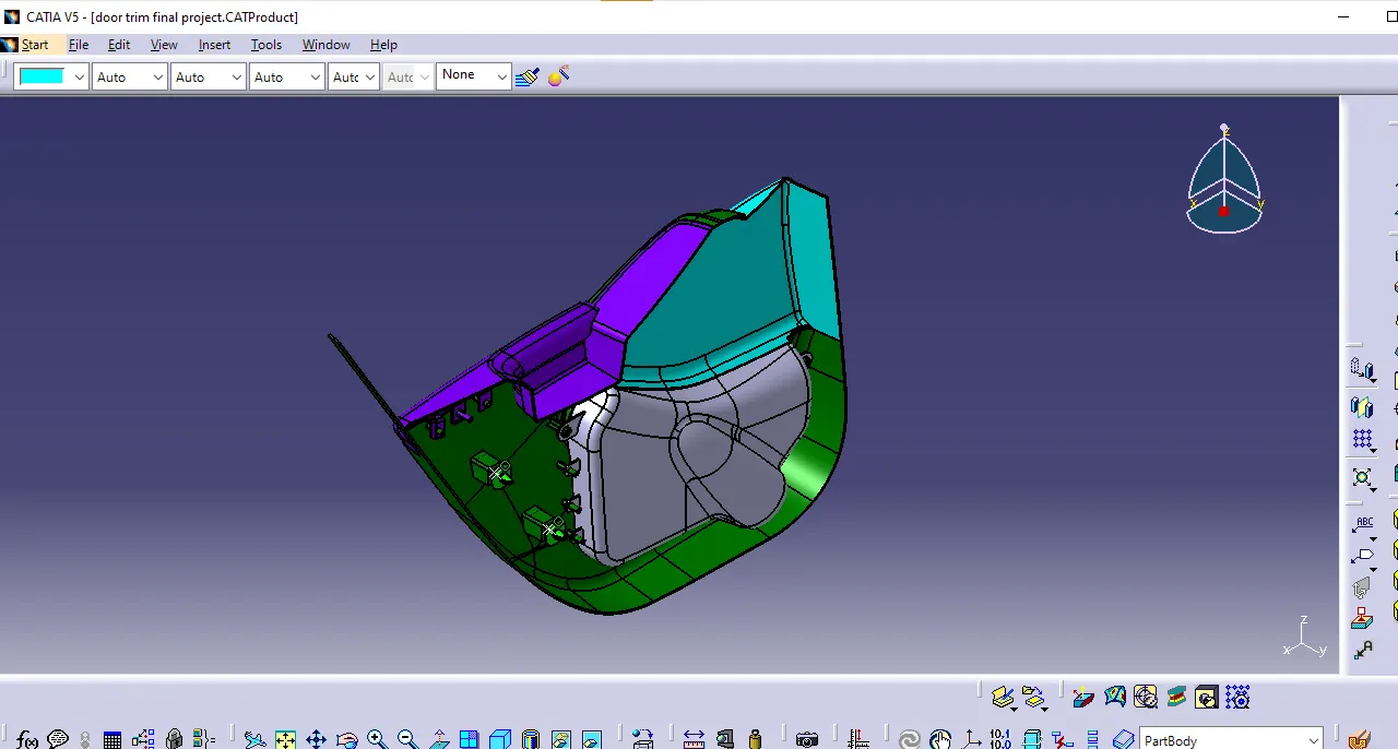
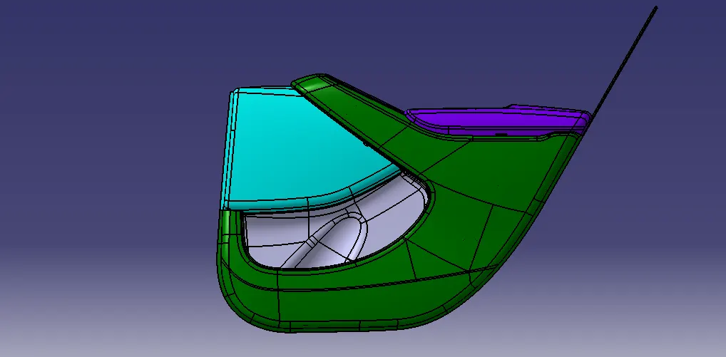
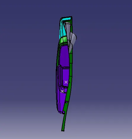
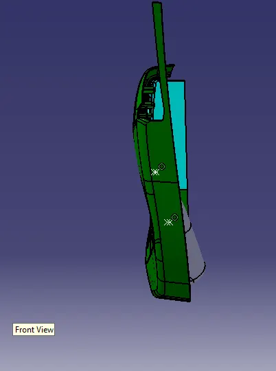
Screenshot view of Door Trim Component :