Advanced Sheet Metal Design Using NX Cad Challenge_1_Casing Design
Advanced Sheet Metal Design Using NX Cad Challenge 1 Casing Design
AIM: To design a casing using NX sheet metal application as shown in the above figure.
INTRODUCTION:
The sheet metal casing design is obtained using sheet metal application in NX CAD 12 application.
Various features such as flange, tabs, Cut out, Sketch tools, Hole, Unbend, Re bend and dimple are used while creating the above model.
METHODOLGY:
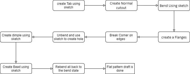
DESCRIPTION: Features Used in Designing the Casing are:
TAB: It is used to create the base feature of a sheet metal which forms the base for our casing design.CUTOUT: It is used to subtract the unwanted portion the sheet metal using sketch.
FLANGE: It is used to create an extended feature for the sheet metal which can be bend and unbend later on.
SKETCH TOOLS: These are the basic drawing in which any kind of operation can be performed, with reference to it like Line, circle, Polygon etc.
HOLE: Used Points sketch to create 4 Threaded Holes of M2 with Fit of Normal H3 and through body.
UNBEND: it's a command which is used to unbend the sheet metal with respect to a stationary face.
DIMPLE: Used to create pitch down or pitch up on a surface with help of a sketch In this case we Used it on the studio spline which we created.
REBEND: It’s used to bring back the old bends which were bent before.
BEEDS: Used for giving more strength for the sheet metal In this case used a circle sketch to create a circular bead and mirrored the feature.
FLAT PATTERN: When working with sheet metal in NX, the flat pattern is created as another part view.The flat-pattern method is where the entire pattern is drafted on a flat surface from measurements, using rulers, curves and straight-edges.
Procedure to create Casing:
1. Open the NX CAD application and open a new model from the selection.
2. Go to application from the top menu bar --> Select Sheet metal module.
3. Go to Home from the top menu --> model sketching
4. In Home --> Select Tab to create a tab from the basic section dimension 60mm in X axis direction and 50mm in Y-axis direction and add thickness of 1mm thickness.
5. In Punch --> select drawn cut out and use the sketch option to create rectangle of dimension 5mm X 30mm.
6. Open Sketch --> draw a symmetric lines parallel to Y-axis (10mm from edges) a to use bend option from form option.
7. Similarly create a bend option -->form options
8. From Bend option --> Create flange or web 5 mm on four corners. The top at the cut out should be inwards and the other to be outwards.9. From Corner --> select Break Corners to chamfer or smoothen the sharp edge
10. In Form -->Select Unbend option. In unbend 1st -->select Base as the centre plate, 2nd -->select all the other features to unbend
11. From Feature option -->Select holes to create hole. Locations are at the four corners on the flanges of radius 5mm and 8mm away fromBoth the adjacent edges
12. Sketch -->draw lines at the flanges and add point + on one flange and use mirror option to create other holes.
13. Features -->use hole -->select screw clearance type select the points, screw type is M2 and Fit is Normal H13 and the depth is through body.
14. Create the below drawing at the centre plate plane. Sketch -->Polygon with sides of 5mm from the centre’s.
15. Sketch --> Studio splines select by poles and use the degree --> closed and movement --> closed and movement --> view. Poles are 16 poles.
16. Punch --> Dimple option to create a dimple about the sketch.
17. Punch --> Dimple --> Create sketch, create circle of 5 mm radii 8mm from adjacent edges. Use mirror feature to mirror the circle and the dimple.
18. Punch --> Louver use sketch and create a 10 mm horizontal line, louver properties depth 3 mm and width 4 mm and rounding edges 1 mm
19. Form -->Unbend option --> select base plate and rest of them to unbend the feature
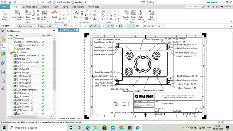
20. Flat pattern --> select Flat pattern -->select OK21. Application --> drafting option -->Home -->Name of the file and create base views
The following are the different Views:
1.Casing ISO view:
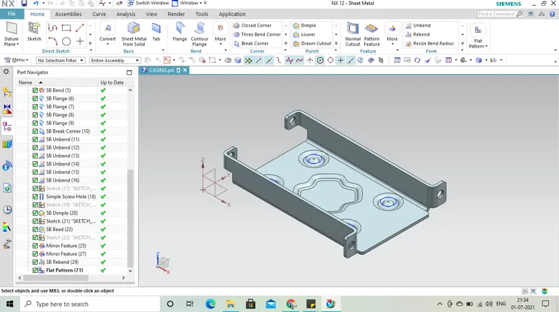
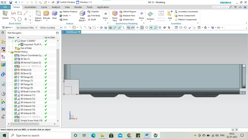
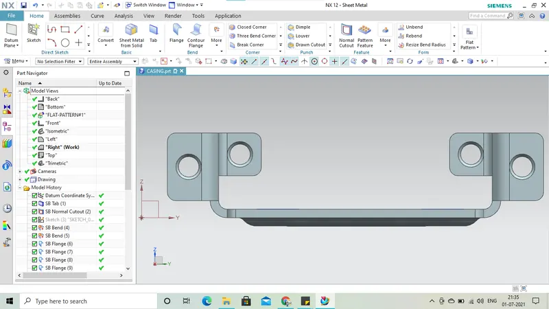
2.Casing Front view
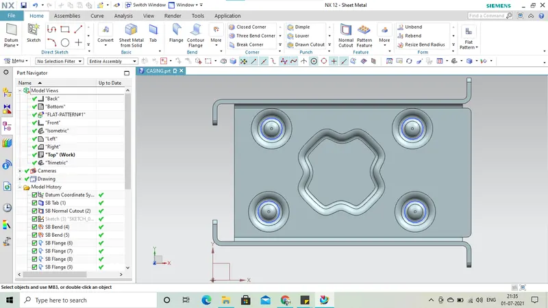
3.Casing TOP view:
4.Casing Right Side view:
5.Casing Draft :
Conclusion :
We can conclude that the Casing is designed and Flat pattern drafting is done using the Sheet metal application of NX CAD.