Final Assembly and Rendering of American Chopper
OBJECTIVES: To be able to design an industrial product keeping the design intent and to design, assemble, render and present American Chopper bike. To sketch and build photorealistic American chopper using Solid works and Solid works Visualize and to gain knowledge of Solid and surface modelling.
INTRODUCTION:
Products generally get developed in an industry comes out to the customers starting all the way from the mind of a designer through the Rough sketches, design process, simulation process, manufacturing process, and so on. It all starts with an idea of a project like spark required for matchstick, which is then followed by design, simulation, manufacturing, testing, and finally marketing. In this project, a unique model of American Chopper is designed, assembled, and rendered using SOLIDWORKS as the CAD tool. The complete design process is accomplished with an industrial approach. This design project is a part of the design course in Skill-Lync.
American Chopper is a type of custom motorcycle which emerged in California in the late 1950s. The chopper is perhaps the most extreme of all custom styles, often using radically modified steering angles, a low seat for improvised ergonomics and lengthened forks for a stretched-out appearance. motorcycle which emerged in California in the late 1950s. American Chopper is a good model to work on because it has some extreme features that are brought in by its unique design. Being able to design, and render such a model can ensure the industry skills of a person and boost up the creativity of design engineer as well as a designer with much flexibility.
DESIGN METHODOLOGY:
Before you actually design the model, it is helpful to plan out a method of how to create the model. After you identify needs and isolate the appropriate concepts, you can develop the model:
Sketches: Create the sketches and decide how to dimension and where to apply relations.
Features: elect the appropriate features, such as extrudes and fillets, determine the best features to apply, and decide in what order to apply those features.
Assemblies: Select the components to mate and the types of mates to apply.
Design and engineering relationships:
Due to the high importance of mechanical components or even exposed engines to motorcycle styling, almost always designers will have a greater sensitivity to and awareness of engineering than will typical car designers. In OEM situations, large teams of professional engineers and specialists will collaborate on each project development, allowing the designer to focus on the more intangible or subjective aspects of design, such as styling, human-machine interface psychology, and market and cultural relationships. In other matters such as pure mechanical ergonomics
Research and Concept Design:
In OEM motorcycle design, the normal procedure of developing a new motorcycle involves the same steps in other professional design disciplines: identifying a target consumer, researching them to identify benchmarks and project targets, then proposing concept directions in a written form known as a Design Brief or QFD. From this point, artwork is developed to visually communicate the designer's ideas. These are presented in 2Db drawing or illustrated form, from which a winning direction is down selected for further development. Once a satisfactory design is established on paper (the term paper is a generalization that can include traditional hand renderings, digital artwork or CAD drawings), then full scale modelling begins to realise the design in tangible 3D form.
Styling:
Often used as an interchangeable term with "design", styling is in fact just one component of the design process. Typically, styling is developed through sketches, renderings and illustrations then realised in 3D form using automotive styling clay, specialised industrial modelling foams in increasingly limited cases plaster or body filler. As the most subjective part of the design process, the various members of the development team must depend heavily on the judgment, skill and experience of the appointed designer to create an appropriate look.
Parallel development:
Because of the need to reduce development time and costs, the "styling" design model is usually developed in parallel with the engineering 3D design. While there is an increasing amount of digital design input in the modern OEM design process, nearly all major motorcycle manufacturers still rely on full scale clay models to render the master style model, then scan and import the styling surfaces into suitable 3D software packages (Alias, CATIA, ISEM Surf) for integration into the 3D engineering CAD platform (Solid works, CATIA, Pro Engineer, etc.)
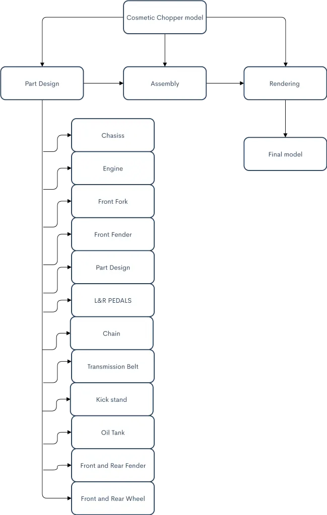
This particular bike is designed starting from the thought of the design from a designer. In general, a normal motorbike consists of at least a few hundreds of parts in total. But this project builds a cosmetic model rather than the working model so it mainly focuses on the design of all the mechanical components, assembly and rendering for visualization of the final product. Here, several parts are designed as multi-body parts rather than a single body which will ease our workflow during the whole design and assembly process. The whole design methodology is depicted in the flowchart below:
Design Process:
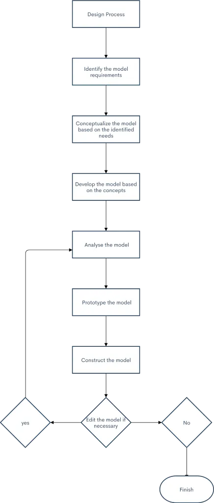
The design process usually involves the following steps:
- Identify the model requirements.
- Conceptualize the model based on the identified needs.
- Develop the model based on the concepts.
- Analyse the model.
- Prototype the model.
- Construct the model.
- Edit the model if necessary.
PROJECTION AND VIEWS:
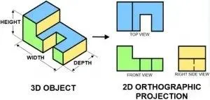
Axonometric projection is a type of orthographic projection used for creating a pictorial drawing of an object, where the lines of sight are perpendicular to the plane of projection, and the object is rotated around one or more of its axes to reveal multiple sides.
"Axonometry" means "to measure along axes". In German literature, axonometry is based on Pahlke's theorem, so that the scope of axonometric projection encompasses every type of parallel projection, including not only oblique projection, but also orthographic projection and therefore Multiview projection. However, outside of German literature, the term "axonometric" is often used to make an explicit distinction from Multiview projection, because axonometric projection allows for the depiction of more than one "side" of an object, whereas a Multiview projection allows for the depiction of only one "side" of an object:
A Multiview projection depicts an object from one of six primary views (e.g., front, right, left, top, bottom, or back); one of the principal axes of the object (e.g., the z or "depth" axis) is necessarily perpendicular to the projection plane, and thus such a projection can depict only one "side" of the object. Because Multiview projections are a fundamental facet of technical illustration, a depiction that results from another type of projection is often called an "auxiliary" view.
In contrast, an axonometric projection may depict an object such that none of the principal axes of the object is perpendicular to the projection plane, and thus more than one "side" of an object may be represented simultaneously (that is to say, the z or "depth" axis may be represented); usually, the projection is such that the images of any 2 axes are not collinear, so that the angles between projected lines help to distinguish each dimension. when it is possible to depict more than one side of an object, it may be said that the object is being viewed from a "skew" angle.
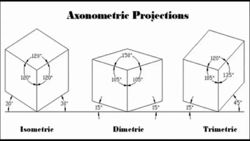
The three types of axonometric projection are isometric projection, dimetric projection, and trimetric projection, depending on the exact angle at which the view deviates from the orthogonal. Typically, in axonometric drawing, as in other types of pictorials, one axis of space is shown as the vertical.
In isometric projection, the most commonly used form of axonometric projection in engineering drawing, the direction of viewing is such that the three axes of space appear equally foreshortened, and there is a common angle of 120° between them. As the distortion caused by foreshortening is uniform, the proportionality between lengths is preserved, and the axes share a common scale; this eases the ability to take measurements directly from the drawing. Another advantage is that 120° angles are easily constructed using only a compass and straightedge.
In dimetric projection, the direction of viewing is such that two of the three axes of space appear equally foreshortened, of which the attendant scale and angles of presentation are determined according to the angle of viewing; the scale of the third direction is determined separately. Dimensional approximations are common in dimetric drawings.
In trimetric projection, the direction of viewing is such that all of the three axes of space appear unequally foreshortened. The scale along each of the three axes and the angles among them are determined separately as dictated by the angle of viewing. Dimensional approximations in trimetric drawings are common and trimetric perspective is seldom used in technical drawings.
Terminology: These terms appear throughout the SOLIDWORKS software and documentation.
Origin: Appears as two blue arrows and represents the (0,0,0) coordinate of the model. When a sketch is active, a sketch origin appears in red and represents the (0,0,0) coordinate of the sketch. You can add dimensions and relations to a model origin, but not to a sketch origin.
Plane: Flat construction geometry. You can use planes for adding a 2D sketch, section view of a model, or a neutral plane in a draft feature, for example. Plane Straight line used to create model geometry, features, or patterns.
Axis: You can create an axis in different ways, including intersecting two planes. The SOLIDWORKS application creates temporary axes implicitly for every conical or cylindrical face in a model. Axis Boundaries that help define the shape of a model or a surface.
Face: A face is a selectable area (planar or nonplanar) of a model or surface. For example, a rectangular solid has six faces.
Edge: Location where two or more faces intersect and are joined together. You can select edges for sketching and dimensioning, for example.
Vertex: Edge Point at which two or more lines or edges intersect. You can select vertices for sketching and dimensioning
Feature Manager design tree: Displays the structure of the part, assembly, or drawing. Select an item from the Feature Manager design tree to edit the underlying sketch, edit the feature, and suppress and Un suppress the feature or component
Property Manager: Provides settings for many functions such as sketches, fillet features, and assembly mates.
Configuration Manager: Lets you create, select, and view multiple configurations of parts and assemblies in a document. Configurations are variations of a part or assembly within a single document. For example, you can use configurations of a bolt to specify different lengths and diameters.
Menus: You can access all SOLIDWORKS commands using menus. SOLIDWORKS menus use Windows conventions, including submenus and checkmarks to indicate that an item is active. You can also use context-sensitive shortcut menus by clicking the right mouse button.
Toolbars: You can access SOLIDWORKS functions using toolbars. Toolbars are organized by function, for example, the Sketch or Assembly toolbar. Each toolbar comprises individual icons for specific tools, such as Rotate View, Circular Pattern, and Circle. You can display or hide toolbars, dock them around the four borders of the SOLIDWORKS window, or float them anywhere on your screen. The SOLIDWORKS software remembers the state of the toolbars from session to session. You can also add or delete tools to customize the toolbars. Tooltips display when you hover over each icon.
Command Manager: The Command Manager is a context-sensitive toolbar that dynamically updates based on the active document type. When you click a tab below the Command Manager, it updates to show the related tools. Each document type, such as part, assembly, or drawing, has different tabs defined for its tasks. The content of the tabs is customizable, similar to toolbars. For example, if you click the Features tab, tools related to features appear. You can also add or delete tools to customize the Command Manager. Tooltips display when you hover over each icon.
Shortcut Bars: Customizable shortcut bars let you create your own sets of commands for part, assembly, drawing, and sketch mode. To access the bars, you press a user-defined keyboard shortcut, by default, the S key.
Context Toolbars: Context toolbars appear when you select items in the graphics area or Feature Manager design tree. They provide access to frequently performed actions for that context. Context toolbars are available for parts, assemblies, and sketches.
Mouse Buttons: Mouse buttons operate in the following ways:
Left Selects menu items, entities in the graphics area, and objects in the Feature Manager design tree.
Right Displays the context-sensitive shortcut menus.
Middle Rotates, pans, and zooms a part or an assembly, and pans in a drawing.
Mouse gestures: You can use a mouse gesture as a shortcut to execute a command, similar to a keyboard shortcut. Once you learn command mappings, you can use mouse gestures to invoke mapped commands quickly. Mouse gestures to activate a mouse gesture, from the graphics area, right-drag in the gesture direction that corresponds to the command. When you right-drag, a guide appears, showing the command mappings for the gesture directions.
Customizing the User Interface: You can customize the toolbars, menus, keyboard shortcuts, and other elements of the user interface
Handles: You can use the Property Manager to set values such as the depth of an extrude. You can also use graphic handles to drag and set parameters dynamically without leaving the graphics area.
Previews: With most features, the graphics area displays a preview of the feature you want to create. Previews are displayed with features such as base or boss extrudes, cut extrudes, sweeps, lofts, patterns, and surfaces.
Pointer Feedback: In the SOLIDWORKS application, the pointer changes to show the type of object, for example, a vertex, an edge, or a face. In sketches, the pointer changes dynamically, providing data about the type of sketch entity and the position of the pointer relative to other sketch entities.
Selection Filters: Selection filters help you select a particular type of entity, thereby excluding selection of other entity types in the graphics area. For example, to select an edge in a complex part or assembly, select Filter Edges to exclude other entities. Filters are not restricted to entities such as faces, surfaces, or axes. You can also use the selection filter to select specific drawing annotations, such as notes and balloons, weld symbols, and geometric tolerances. Additionally, you can select multiple entities using selection filters. For example, to apply a fillet, a feature that rounds off edges, you can select a loop composed of multiple adjacent edges.
DESCRIPTION:
Creating an idea: the idea of the project is presented through sketches and renderings using pen and paper or software like Photoshop and Autodesk Sketchbook Pro. In general, making idea and sketching is done by industrial designer and not much by the design engineer. But for this particular design, the idea of sketch has been redone by me. It is good to have sketching skills in an engineer too because it helps to get the overall idea and to be able to present the idea of any product in the industry or as an individual so that it decreases dependency on an industrial designer. This gives a clear understanding of the components of the bike as well as the proportion, layout, and placing of the components in 2D before going to design in CAD software. Here, the sketch and rendering of the sketch is done using Autodesk Sketchbook Pro software. The following image shows the final sketch with slight rendering to give the overall idea of the product.
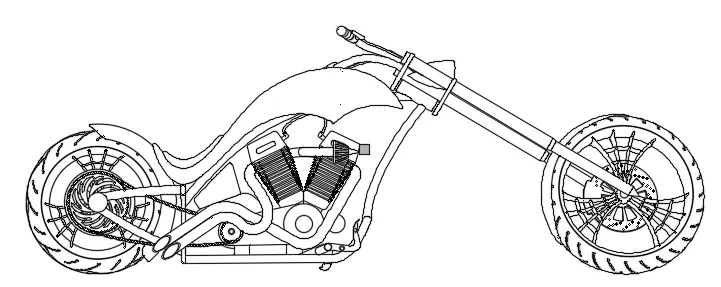
Generating ideas is done by incorporating the elements of what inspires a designer to do so. It is generally done by making use of the mood board. The different views of a product can be drawn as idea of sketches to help a design engineer for a better understanding of the components of the product. After the final sketches are done, it is sent to the design team or the design engineer for the creation of 3D models and its assembly.
Design/3D Modelling: The different views of the sketches done by a designer are brought into the SOLIDWORKS sketching environment and the design of each component is started. To do 3D modelling of any component, we require at least a 2D cross-section sketch which can be converted into 3D using the features within SOLIDWORKS. In SOLIDWORKS, features are generally categorized into two types:
- Sketched Features:
Sketches The sketch is the basis for most 3D models. Creating a model usually begins with a sketch. From the sketch, you can create features. You can combine one or more features to make a part. Then, you can combine and mate the appropriate parts to create an assembly. From the parts or assemblies, you can then create drawings. A sketch is a 2D profile or cross section on a plane. To create a 2D sketch, you use a plane or a planar face. In addition to 2D sketches, you can also create 3D sketches that include a Z axis, as well as the X and Y axes. There are various ways of creating a sketch. All sketches include the following elements:
Origin: In many instances, you start the sketch at the origin, which provides an anchor for the sketch. The sketch on the right also includes a centreline. The centreline is sketched through the origin and is used to create the revolve.
Planes: You can create planes in part or assembly documents. You can sketch on planes with sketch tools such as the Line or Rectangle tool and create a section view of a model. On some models, the plane you sketch on affects only the way the model appears in a standard isometric view (3D). It does not affect the design intent. With other models, selecting the correct initial plane on which to sketch helps you create a more efficient model. Choose a plane on which to sketch. The standard planes are front, top, and right orientations. You can also add and position planes as needed. This example uses the top plane.
Dimensions: You can specify dimensions between entities such as lengths and radii. When you change dimensions, the size and shape of the part changes. Depending on how you dimension the part, you can preserve the design intent.
The software uses two types of dimensions: driving dimensions and driven dimensions.
Driving Dimensions: You create driving dimensions with the Dimension tool. Driving dimensions change the size of the model when you change their values.
Driven Dimensions: Some dimensions associated with the model are driven. You can create driven, or reference dimensions, for informational purposes using the Dimension tool. The value of driven dimensions changes when you modify driving dimensions or relations in the model. You cannot modify the values of driven dimensions directly unless you convert them to driving dimensions.
Sketch Definitions: Sketches can be fully defined, under defined, or over defined. In fully defined sketches, all the lines and curves in the sketch, and their positions, are described by dimensions or relations, or both. You do not have to fully define sketches before you use them to create features. However, you should fully define sketches to maintain your design intent.
Relations: Relations establish geometric relationships such as equality and tangency between sketch entities. Some relations are created by inference. You can also use the Add Relations tool. For example, to create the faucet stems, you sketch a pair of arcs for each stem.
Sketch Complexity: A simple sketch is easy to create and update, and it rebuilds quicker. One way to simplify sketching is to apply relations as you sketch. You can also take advantage of repetition and symmetry. First, sketch a centreline through the origin. Centrelines help to create symmetrical sketch entities. Second the Dynamic Mirror tool to designate the centreline as the entity about which to mirror the sketched circles.
Edit sketch: You can select a sketch in the Feature Manager design tree and edit it. For example, you can edit sketch entities, change dimensions, view or delete existing relations, add new relations between sketch entities, or change the size of dimension displays. You can also select the feature to edit directly from the graphics area.
Hide and show: With certain geometry such as multiple surface bodies in a single model, you can hide or show one or more surface bodies. You can hide and show sketches, planes, and axes in all documents, and views, lines, and components in drawings.
Suppress and Un suppress: You can select any feature from the Feature Manager design tree and suppress the feature to view the model without that feature. When a feature is suppressed, it is temporarily removed from the model (but not deleted). The feature disappears from the model view. You can then Un suppress the feature to display the model in its original state.
Rollback: When you are working on a model with multiple features, you can roll the Feature Manager design tree back to a prior state. Moving the rollback bar displays all features in the model up to the rollback state, until you revert the Feature Manager design tree back to its original state. Rollback is useful for inserting features before other features, speeding up time to rebuild a model while editing it, or learning how a model was built.
Applied Features:
Once you complete the sketch, you can create a 3D model using features such as an extrude (the engine chassis) or a revolve (the wheels).
These features are directly applied to the 3D parts in part design environment of SOLIDWORKS without requiring a sketch. Fillet, chamfer, shell, mirror, body pattern are some examples used in this project.
Some of the most widely used features in this project and the most important are described below:
Extrude: It is just like the protrusion of something out of a plane. It draws out a sketch profile from the sketch plane or any specified plane/face to any other specified plane/face. Extrude is generally the first step for 3D modelling in most of the cases. Extruded Cut: It is just like the Extrude feature but instead of adding material into the part, it removes the part drawn out from the sketch profile.
Revolve: It can revolve a cross-section of a part and make the round part which is complete 360 degrees round or up to some angle. It requires a centreline or axis to revolve the sketch profile.
Shell: Shell is a very powerful tool to create a hollow body out of a solid body without any additional sketch required. It simplifies so many complex designs. It can make a closed hollow body or a hollow body with an opening in some faces.
Sweep: Sweep can be used to create complex features that follow irregular paths or some curves. It can be done using two different sketches; one for the sketch profile and another for the path which the sketch profile follows.
Loft: Loft can join two different shapes at two different planes completely without difficulty. It can create a smooth surface that connects both the profiles.
Project Curve: It is a very powerful tool which can project two different 2D splines from two different planes into a single spline or a curve in 3D which can meet our need.
Mirror: Mirroring certain features or bodies can save a huge amount of time in the design process. It is extensively used throughout the design process.
Combine: It is a feature that can only be applied to the multi-bodies. Several bodies can be added together or can be subtracted from the intersection part of the common part that can be kept. It functions based on the Boolean operation.
Linear and Circular Pattern: These are a very handy tool to create the same instance multiple times in multiple directions. It saves a lot of time and it is very accurate.
Split: It is another powerful tool that can cut a part with the help of a sketch or plane or face or surface and allows removing or cutting the selected parts.
Rollback: Rollback is yet another powerful tool that allows going back to any phase of design in case if we need to edit or add some features later. We can use a roll-up bar while removing errors too. This reduces the rebuild time and avoids further errors in the children features.
Surface sweep: sweeps closed profile along open or closed path to create thin feature model.
Edit feature: Once you create a feature, you can change most of its values. Use Edit Feature to display the appropriate Property Manager. For example, if you apply a Constant radius fillet to an edge, you display the Fillet Property Manager where you can change the radius. You can also edit dimensions by double-clicking the feature or sketch in the graphics area to show the dimensions and then change them in place.
Appearance/Material Application: Material selection is a very crucial part of any product design process. It plays a major role in terms of cost minimization, weight reduction, performance, safety factors, manufacturability, aesthetics, and availability, and so on. Appearance is also one of the key components along with the material application in the product. In this project, appearance is applied based on the material to each part after the completion of part design. Most of the materials are Chromium and a metallic paint of sienna is applied to the fuel tank, oil tank, front and rear fenders, and chassis.
Assembly:
You can combine multiple parts that fit together to create assemblies.
After all, the components of the American Chopper are designed in the part design environment, assembly is then created form the part files. In SOLIDWORKS, the feature which connects or joins two different components is called mate. The parts are imported into the Assembly
In this American chopper, the chassis is fixed first for the ease of assembly. All the components which remain aligned with the chassis mid-plane at any point in time are made coincident with it. All other components that come along with the front fork move with respect to the mid-plane of the chassis, so angle mate is applied between the chassis mid-plane and front fork mid-plane to keep the design intent so that can be turned side to side.
Within the assembly environment, the errors occurred by the interference of the parts are eliminated by editing the part within the assembly. In this case, interference of the exhaust pipe and chassis was eliminated by editing the exhaust pipe of the engine within the assembly. Also, the interference between the chain and the backplate of the chassis was corrected by providing an allowance to the chain by cutting away a portion of the backplate. We have also applied some 'in context features such as copying and mirroring the part in the assembly environment. For example, only the right-hand side pedal was modelled but the left-hand pedal was made by using the in-context features available in the assembly mode. Assembly of American Chopper in SOLIDWORKS
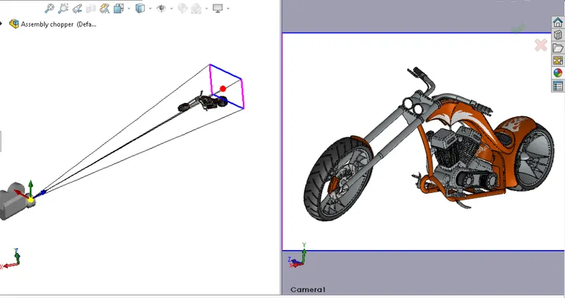
Rendering: Rendering is to make photo-realistic images out of the 3d designs that we have created and assembled in the design process. To render the 3D models, we need to set up the correct scene, lighting, camera views, and apply decals if necessary.
Why is rendering Important? Rendering helps to visualize the product and it allows us to see how it interacts with the environment. It is very essential for the presentation of the product among the potential customers ahead of the actual manufacturing. Also, aesthetics is a very important part of every product in the industry, so to see how the final result looks upon the various materials and appearances applied, it plays a vital role. It also saves a lot of time and money avoiding the real-time testing of its appearance before the actual production. It can also be used for digital marketing purposes without actual production. In the case of such a bike like American chopper, it is very essential to represent the idea, to visualize, pleasing, and satisfying the customers.
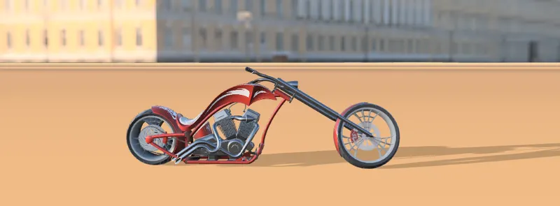
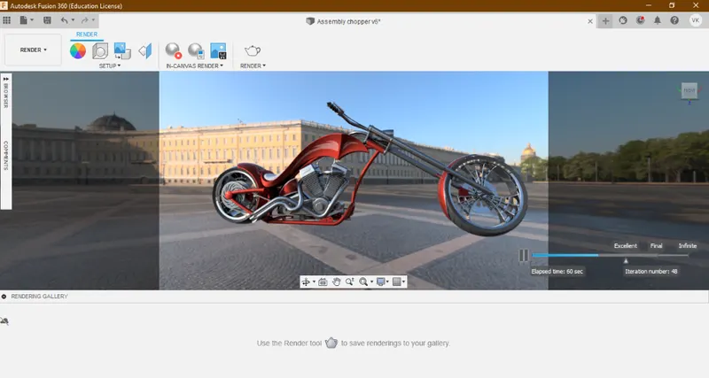
Rendering Tools: • 'Photo view 360' is one of the add-ons of SOLIDWORKS which allows the creating photorealistic rendering. It is integrated with the SOLIDWORKS software. • 'SOLIDWORKS Visualize' is another powerful tool of SOLIDWORKS which comes as separate software and is able to render extremely high quality and photo-realistic images of the product. • Auto desk fusion 360 is an alternative to the rendering took which can be utilized to render high-definition images of the product. However, for this project, only 'Photo view 360' and 'Auto desk fusion 360' has been employed for the rendering purpose.
However, for this project, only 'Photo view 360' and 'Auto desk fusion 360' has been employed for the rendering purpose. Rendering Process: The rendering process includes the following steps: i) Apply scene ii) Apply lights iii) Apply decals iv) Adjust camera views v) Adjust image quality and vi) Render
After the rendering is complete, it is presented among the customers and also for digital marketing.
PART DESIGNS:
In this project, most of the parts are designed to be multi-body parts to make the workflow faster and simpler. It makes a lot easier in the assembly phase and decreases rebuild time too. As long it is a cosmetic model of the bike, it is all solid modelling. The following are the individual parts designed in SOLIDWORKS and rendered in Auto desk fusion 360 with a majority of black appearance although sienna was applied majorly in SOLIDWORKS Photo view 360.
COMPONENTS OF COSMETIC MODEL OF AMERICAN CHOPPER:
- CHASSIS
- ENGINE
- TRANSMISSION BELT AND CHAIN
- PEDAL (L&R)
- KICKSTAND
- FRONT FORK
- FRONT WHEEL
- FRONT FENDER
- REAR WHEEL
- 10. REAR FENDER
- OIL TANK
CHASSIS:
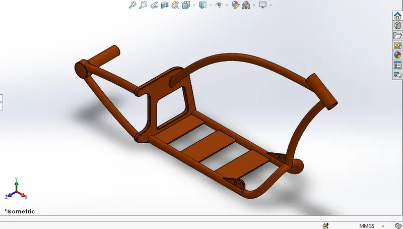
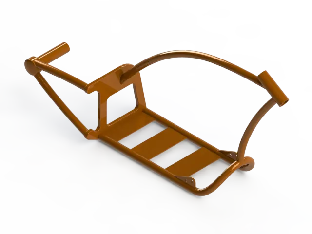
Chassis The chassis is the frame that bears most of the load on the bike. In the design process of this chassis, the mostly applied features are splines, sweeps, project curves, split, etc. The lower tube is mirrored with respect to the mid-plane. The rear plate supports the rear arm which holds the hub from only one direction so it is designed to be stiff enough. Sienna is applied as the appearance for the chassis which automatically sets the material to the part as well. Here is the rendered image of the chassis in black.
Features used in it are: revolve, boss extrude, cut extrude, fillet, chamfer, sweep, projected curve, split.
Revolve: It is used in revolving sketch profile around an axis to create a solid feature.
Boss extrude: Extruding sketch profile or selected contours in one or more direction to create a solid feature.
Cut extrude: It cuts a solid model by extruding sketch profile or selected contours in one or more direction.
Fillet & chamfer: Creates a round internal or external edges around the edges of face. chamfer creates an angle or distance edge around the edges of face.
Sweep: Sweeps a closed profile in an open or closed path to create a solid model.
Split: It is used for trimming or removal of part from selected sketch.
CAD MODEL PERFORMED IN SOLIDWORKS AND RENDER IN PHOTO VIEW 360
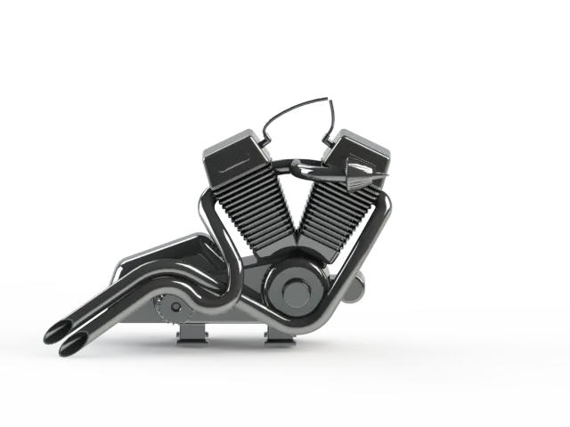
ENGINE:
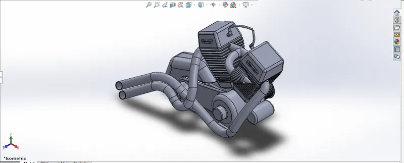
Features which were used in creating Engine are: revolve, boss extrude, cut extrude, sweep, split, fillet, chamfer, circular and linear pattern, dome, reference plane, combine, composite curve, projected curve.
The engine used in this bike is a V engine with two exhaust pipes. Although it is the solid modelling of the engine block, it covers most of the
aspects of the engine block. It incorporates the cooling fins, spark plug representation, intake and exhaust manifolds, transmission unit with the
transmission belt, and pulleys. The material applied to the engine body is Chromium. In this model, every part such as cylinder, engine body,
pulleys, intake, and exhaust pipes are modelled to be a single body so the same material applies to the entire part. This part employs some unique
features like complex spline shapes, project curves, sweeps, etc.
Dome: use to create circular or elliptical face at selected portion.
Combine: combines two or more bodies.
Composite curve: combination of two projected curves.
Circular and Linear pattern: creates and circular and linear pattern of selected sketch profile along linear or circular path.
CAD MODEL PERFORMED IN SOLIDWORKS AND RENDER IN PHOTO VIEW 360
TRANSMISSION BELT AND CHAIN:
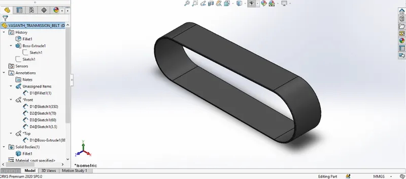
This transmission belt is designed to adapt to the two pulleys created on one side of the engine block. It is a simple model created using very fewer
features such as extrude and fillet. In this part also, chromium is applied.
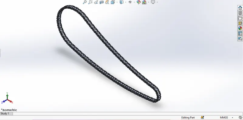
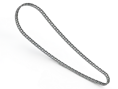
It is the most complex part of the whole design project. It consists of 390 bodies including separate bodies for all the inner plates, outer plates, and the pins. The major feature used in this part is the Curve driven pattern which allows each instance of chain parts to follow the curve drawn initially
for the chain. It is essential to keep all the elements of this chain as a separate body because it has to rotate along the curve and around the sprocket which is not possible if it is merged to make a single body.
Features used in it are: boss extrude, fillet, mirror, curve driven pattern
Mirror: It mirrors face or bodies along selected mirror plane.
Curve driven pattern: it creates pattern of selected sketch profile along curve.
CAD MODEL PERFORMED IN SOLIDWORKS AND RENDER IN PHOTO VIEW 360
FRONT FORK:
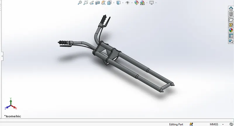
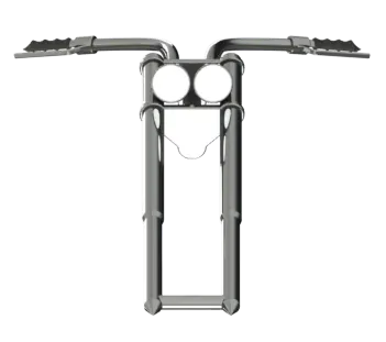
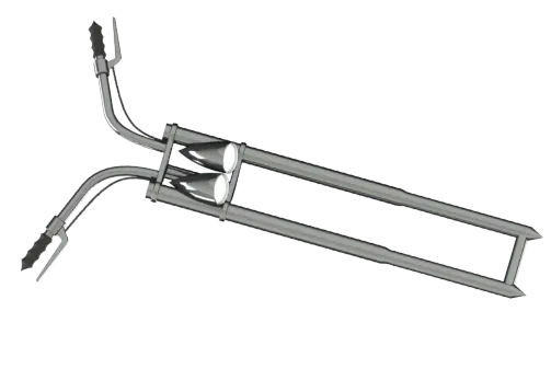
It is the most unique part of this American Chopper bike. It is longer than usual bikes and the angle is extremely low with respect to the horizontal.
The handles are shorter and are customized according to their comfort. For this model, revolve features is mostly used. It consists of two headlights
so, it is completely symmetrical with respect to its mid-plane. This is why first the half of it is designed and is mirrored to the mid-plane and is
merged together to form a single body. The area light is applied in the case of headlight’s appearance.
Features used in creating front fork are: revolve, cut extrude, boss extrude, combine, fillet, axis, linear pattern, dome, body move/copy, sweep, cut revolve. Cut Revolve: cuts solid model by revolving sketch profile around axis in one or two direction.
CAD MODEL PERFORMED IN SOLIDWORKS AND RENDER IN PHOTO VIEW 360
PEDAL:
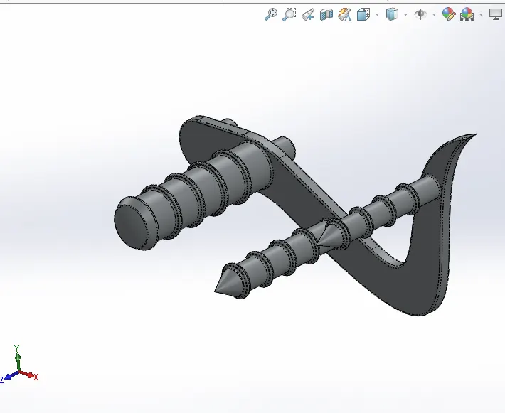
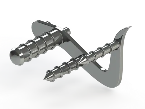
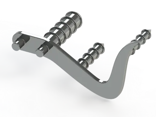
There are two pedals, left and right. Among them, only the right pedal was sketched and designed in the part design environment and the left was made using the in-context features of the assembly environment. It is designed to sit into the holes provided at the bottom of the chassis on both sides. The mostly used features in this part is extrude and linear pattern.
Features used are: boss extrude, revolve, fillet, dome, chamfer, linear pattern.
CAD MODEL PERFORMED IN SOLIDWORKS AND RENDER IN PHOTO VIEW 360
KICK STAND:
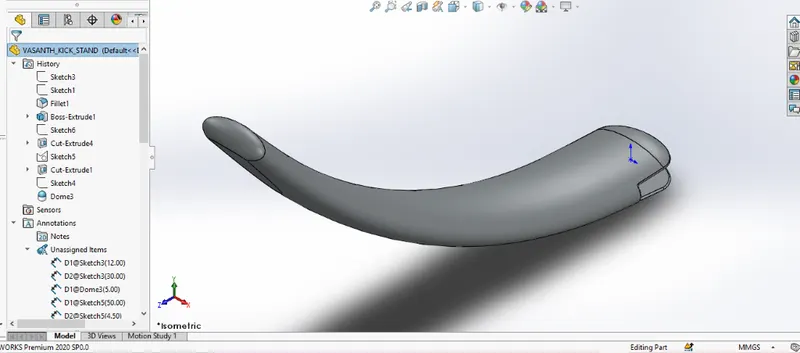
Features used in it are: loft, dome, split, cut and boss extrude, fillet. Loft: adds material between two or more profile to create solid feature.
Kickstand for this bike is of a very simple kind made by the application of sweep feature. An opening is kept for it to fix it to the chassis and the Dome is applied at the ends of the kickstand. It is also applied with chrome material.
CAD MODEL PERFORMED IN SOLIDWORKS AND RENDER IN PHOTO VIEW 360
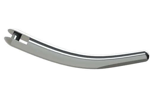
OIL TANK:
The oil tank is placed above the engine block which is also made hollow inside. Extrude and shell are the major features used in this part.
CAD MODEL PERFORMED IN SOLIDWORKS AND RENDER IN PHOTO VIEW 360
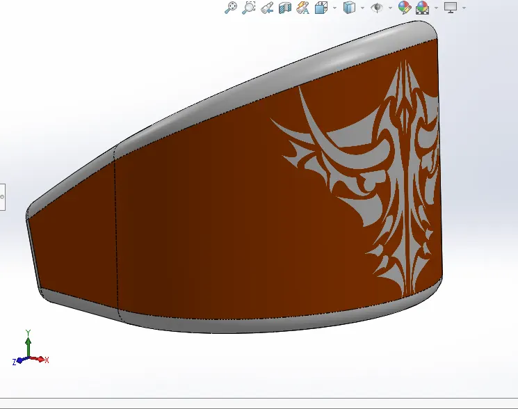
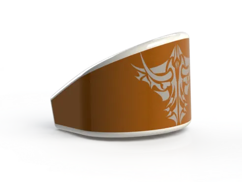
FUEL TANK:
Features used in it are: surface sweep, surface loft, boundary surface, surface trim, cut sweep, shell, fillet, surface extrude, surface knit, mirror, projected curve. Surface sweep: sweeps closed profile along open or closed path to create thin feature model. Surface loft: Adds material between two or more profile to create thin feature model. Boundary surface: adds material in sketch profile between two direction to create a thin feature. Surface trim: Trims or remove material from selected surface sketch. Cut sweep: cuts thin surface model by sweeping closed profile along open or closed path. Surface extrude: extrudes sketch profile or selected contours in one or more direction to create a thin feature model. Surface knit: knits two or more bodies so that no gap is in between them and forms solid model.
The fuel tank for this American Chopper is designed as per the info sketch. It is hollowed out to make a tank for the fuel inside. The mostly
applied features include extrude surface, boundary surface, shell, and knit surface. Sienna is assigned as its appearance and decals are applied
during the time of rendering the final rendering. It consists of a seat that is very low and the appearance of the cloth pattern is applied.
CAD MODEL PERFORMED IN SOLIDWORKS AND RENDER IN PHOTO VIEW 360
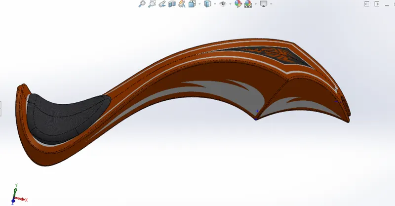
FRONT FENDER:
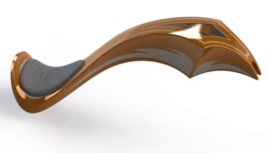
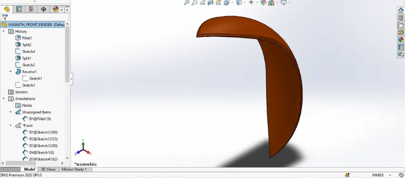
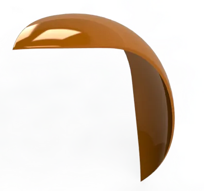
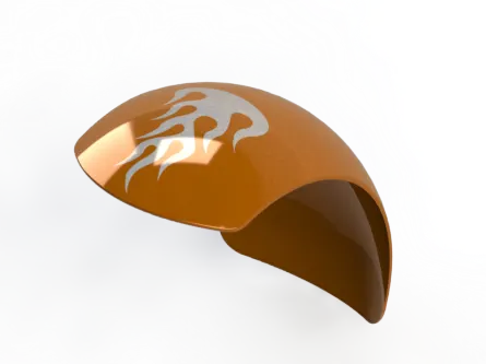
Features used in it are: axis, revolve, fillet, split. The front fender for this bike is designed simply by revolving the cross-section and cutting away material at the end to make it pointed. Revolve and split tools are the most used tools here. Sienna is applied in the appearance of this part.
CAD MODEL PERFORMED IN SOLIDWORKS AND RENDER IN PHOTO VIEW 360
FRONT WHEEL:
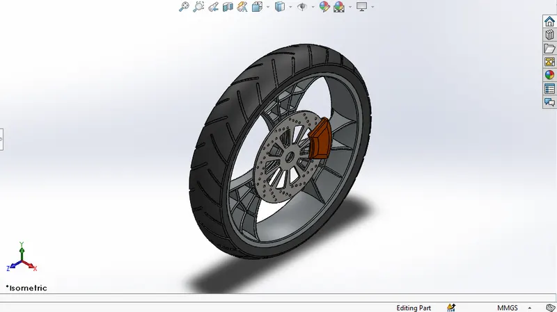
Features used in it are: boss and cut extrude, revolve, fillet, chamfer, cut revolve, combine, circular pattern, axis. The front wheel is thinner than the rear wheel. It is designed to be a multi-body part consisting of the rotor, sprocket, rim, tire, and the calliper all are made to be single bodies. Mostly used features include revolve, extruded cut, and circular pattern. The majority of the parts are of chrome.
CAD MODEL PERFORMED IN SOLIDWORKS AND RENDER IN PHOTO VIEW 360
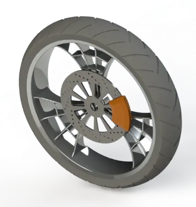
REAR WHEEL:
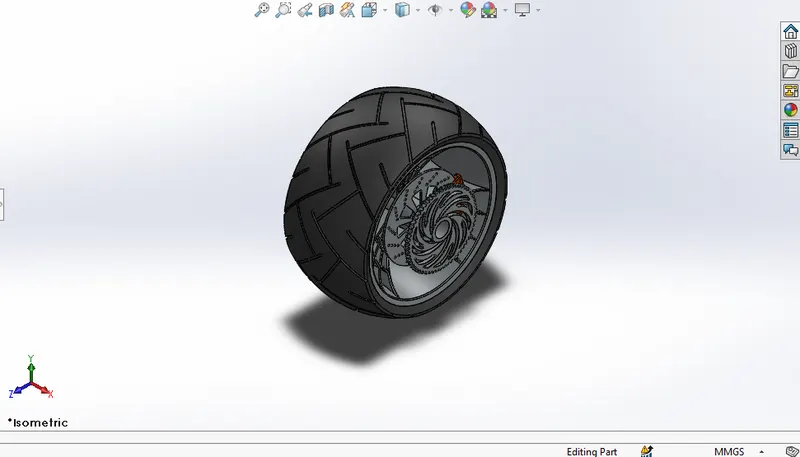
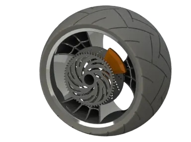
Features used in it are: boss and cut extrude, revolve, fillet, chamfer, cut revolve, combine, circular pattern, axis. The rear Wheel is much thicker than the front wheel. Just like the front wheel, it is also designed to be a multi-body part consisting of the rotor, sprocket, rim, tire, and the calliper all in a single part. Mostly used features include revolve, extruded cut, and circular pattern. The majority of the parts are of chrome.
CAD MODEL PERFORMED IN SOLIDWORKS AND RENDER IN PHOTO VIEW 360
REAR FENDER:
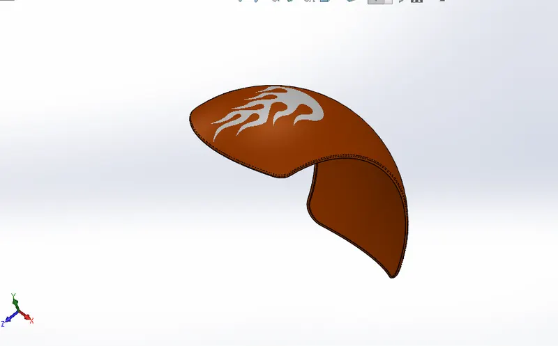
Features used in it are: axis, revolve, fillet, split. The rear fender is thicker but shorter compared to the front fender. It doesn't have a pointed end like the front fender, rather rounded end as in the Idea of sketch. Revolve and split tools are the most used tools here. Sienna is applied in the appearance of this part.
CAD MODEL PERFORMED IN SOLIDWORKS AND RENDER IN PHOTO VIEW 360
Camera setup on the Assembly:
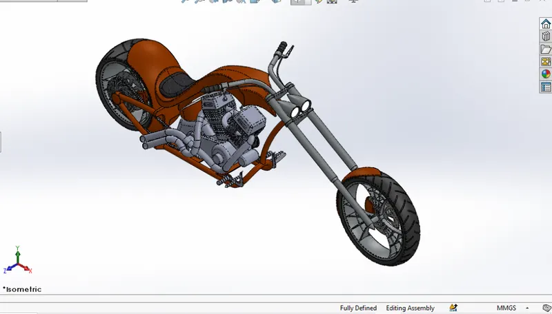
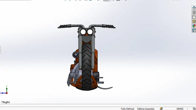
ASSEMBLY CAD MODEL IN SOLID WORKS ISO VIEW:
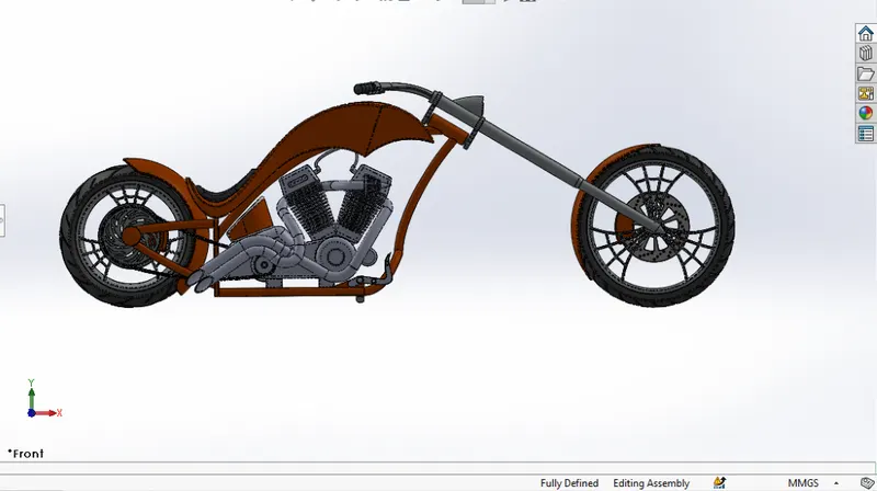
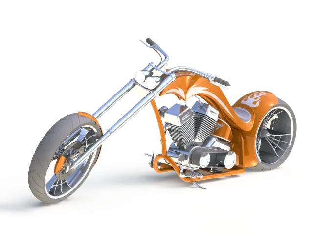
RENDERED MODEL OF ASSEMBLED AMERICAN CHOPPER PERFORMED IN PHOTOVIEW 360:
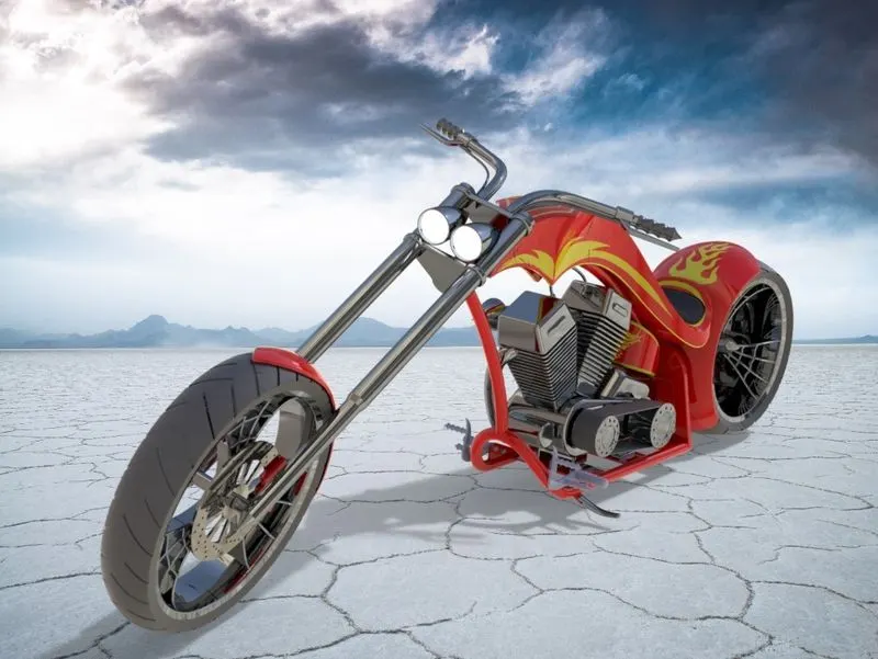
RENDERED MODEL OF ASSEMBLED AMERICAN CHOPPER PERFORMED IN SOLID WORKS VISUALIZE WITH DIFFERENT APPEREANCE:
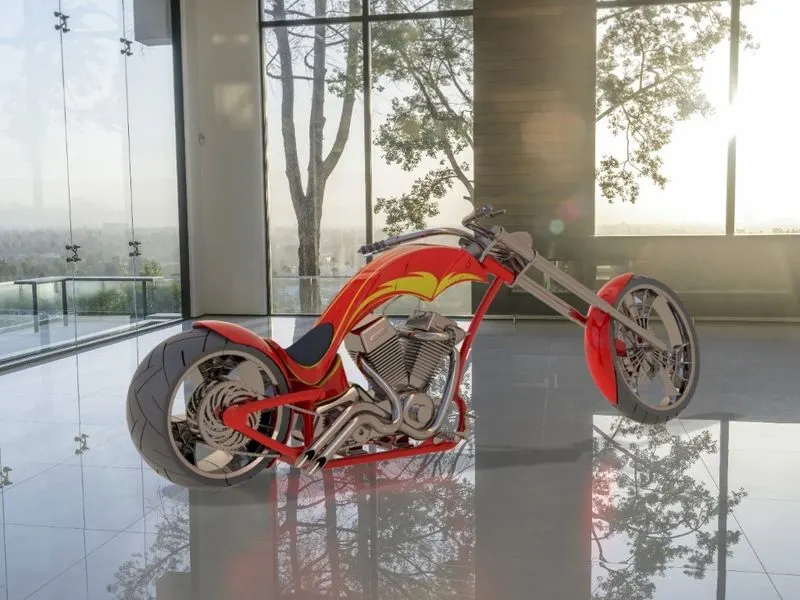
RENDERED MODEL OF ASSEMBLED AMERICAN CHOPPER PERFORMED IN AUTODESK FUSION 360 WITH DIFFERENT APPEREANCE:
CONCLUSION:
Creation of CAD MODEL of each and every part of AMERICAN CHOPPER along with its ASSEMBLY was successfully completed in SOLIDWORKS.
To give a realistic view of it RENDERING was performed in both PHOTOVIEW 360 and SOLIDWORKS VISUALIZE.
TAKEAWAY OF THIS PROJECT:
This project helps to learn new and enhance many existing skills required for a design engineer in the industry. The major takeaways of this project are:
Design industrial approach:
Design is an iterative process and it involves many professionals such as designer, design engineer, simulation engineer, CAE engineer, etc. Being a
design engineer, one must be able to communicate with all the professionals, understand their responsibilities, and understand the design process
maintaining the coordination with others. One must not only know the CAD tools but also the efficient way of using it as the industry needs. This project has sharpened all those aspects.
Application of Parametric Modelling:
What is Parametric Modelling? Parametric modelling is a modelling process where we can modify the design, features at any point in time. The different elements of the model, such sketch entities, features can be assigned to a parameter that can be changed anytime. It is a very powerful tool as it saves all the parameters for forever and it can also be employed to add or edit features within a part from a generative design environment, where the parameters are not available initially.
Use of Design Intent:
Design Intent is the prediction of how the design will behave in the future when certain changes are made or when certain features are applied. In an industry, a design engineer should be able to use the features in such a way that even if any modifications are needed at any time, it should be modifiable in no time.
One can keep the design intent making the use of the following features:
End Conditions: While applying end conditions, care must be taken and it should be predicted in what way it will behave if any additional changes have to be made later. The end conditions should be applied in such a way that it will affect only the current part and not others. For example, in this extruded cut of the sprocket in the wheel, it is required to keep the end condition ‘up to next’ because if ‘through all’ is selected, it can cut other bodies present in the part too.
Feature Scope: Feature Scope appears in the property manager only in the case of multi-bodies. A certain feature can be applied to certain bodies and can be skipped to others by selecting manually form the feature scope. If it is left as default, it will affect all the bodies present in the part.