Week 12- Final project
Aim:
- To use the supplied Class-A surface to create the Door Handle Component.
- To create the tooling axis that satisfies the draft angle requirements for the specified Class-A Surface and to Create thickened part.
- To attach the component's B side features.
- To run the model through the Draft analysis.
- Creation of parting lines and check tooling feasibility.
1. Class A Surface:
To begin with this, a tooling axis is created for the Class A Surface, meeting the requirement of draft angle. The Tooling Direction is basically the direction that the mould pulls a part. The mould is built in two separate pieces, basically. You have a Cavity side and you have the Core side. The Core pulls apart from the Cavity and that's the Dye line or the Tooling Direction. The pictures provided below are the Class A Surface of different part of the Door Trim like Lower Substrate, Arm Rest, Map Pocket.
The Figure 1.1 represents one of the parts of Door Trim, Arm Rest. This part, Arm Rest, had a patch, so it had been rectified as Improved A class. This was rectified before offsetting Class A, so that, I can reduce the patches in the offset. To clear the patch, I used commands like multiple extract, extrapolate, trim and joined it.
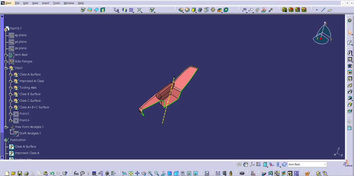
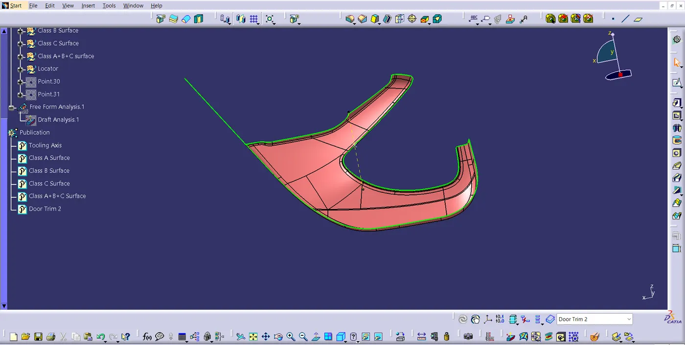
Fig 1.2
The Figure 1.3 represents, the Upper Map Pocket of the Door Trim. Class A Surface of the Upper Map Pocket also didn't had patches to improve.
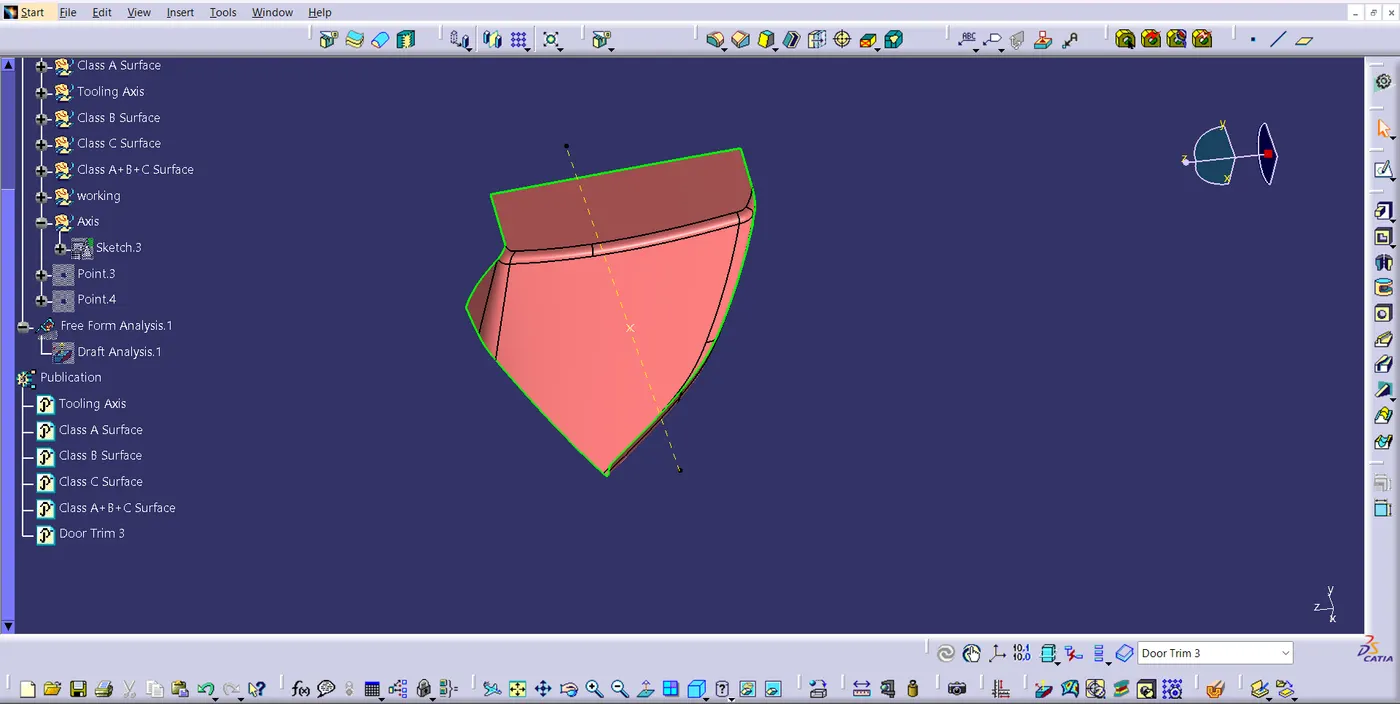
Fig 1.3
The part given in Figure 1.4 is Lower Map pocket. There were no patches to rectify.
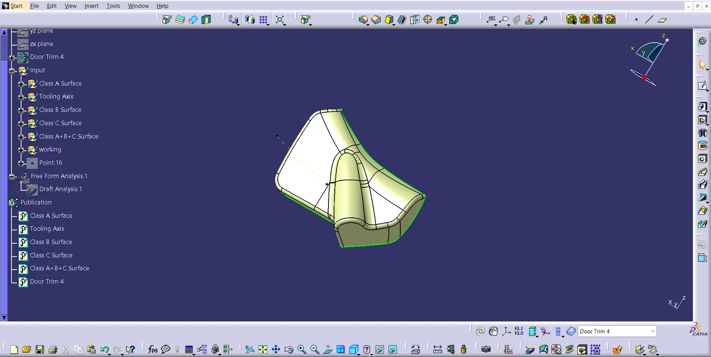
Fig 1.4
After Improving Class A Surface (if needed), I created the offset of Class A Surface in the required direction to the thickness of 2.5mm.
2. Class B Surface:
The Class B surface is the underside of a fascia that you may not always be able to see. I created the offset of Class A Surface in the required direction to the thickness of 2.5mm. Next, I was clearing some patches in the some of the offset. The main reason for the patches is fillet on the Class A Surface.
The Figure 2.1 depicts, the Class B Surface of the part, Arm Rest. After, Improving the Class A Surface, I used the command offset, to create Class B Surface. There were many patches after offset. In order to create the Class B Surface, I cleared all the patches using the commands like multiple extract, extrapolate, trim, multi-section surface, sweep, etc.
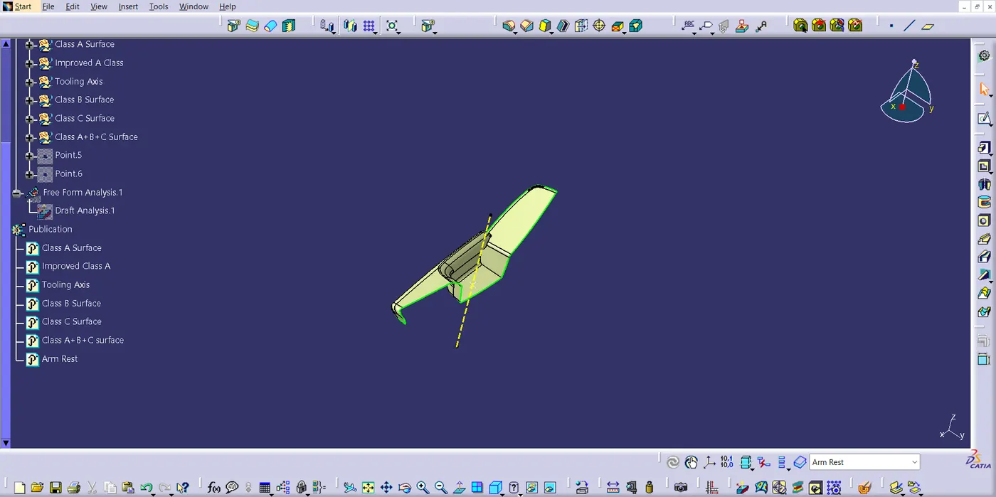
Fig 2.1
The below given figure 2.2, it is the Lower Substrate of the Door Trim. It didn't have any patches after creating the offset.
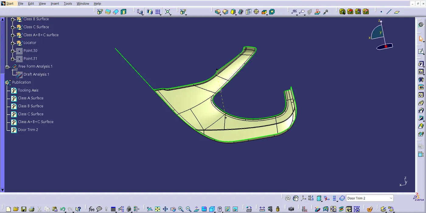
Fig 2.2
The below given Figure 2.3 and Figure 2.4 are Upper Map Pocket and Lower Map Pocket respectively. Figure 2.4, Lower Map Pocket, didn't have any patch to improve but Figure 2.3 had some patches to rectify. I rectified it using the command multi-section surface.
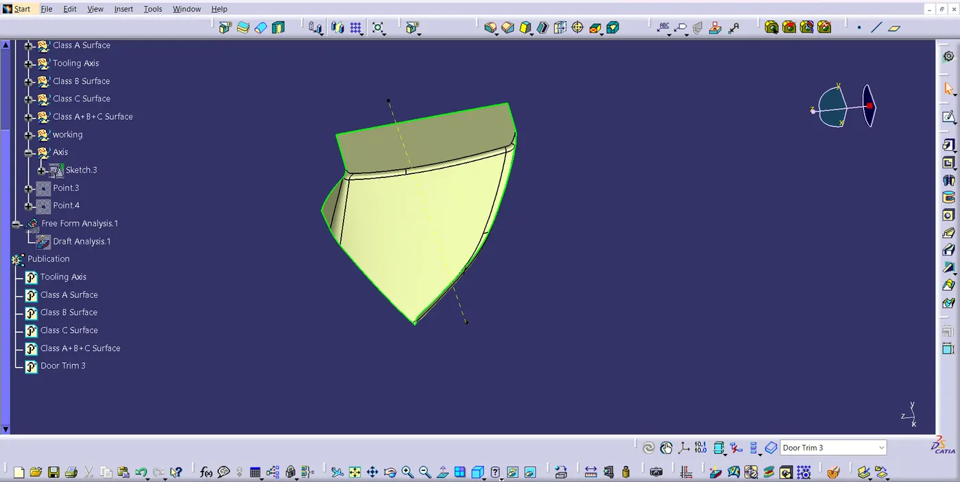
Fig 2.3
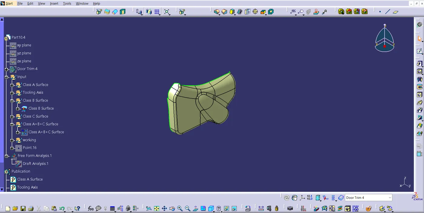
Fig 2.4
Once the patches are cleared in required parts, The Class B Surface is created.
3. Class C Surface:
The Class C Surface, it is a surface that is used to create a closed component/part. It is mostly not readily visible. Swept the boundary of the Class A surface, so that, I can create Class C surface. After creating the C Surface, I was able to join class A, B and C surface as a final part, which had a closed boundary.
Figure 3.1 represents the Class C Surface of arm rest. I created Class C surface using the commands like sweep, extrapolate, blend and multi-section surface.
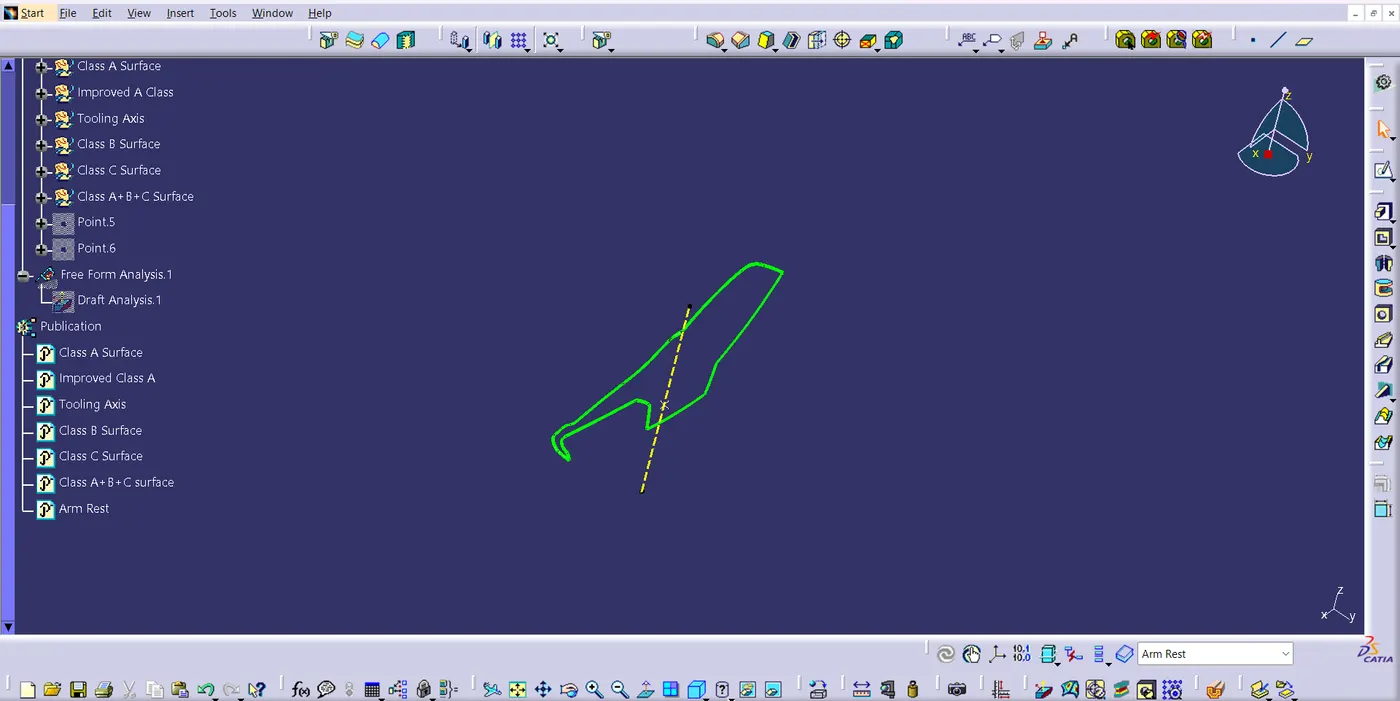
Fig 3.1
The Figure 3.2, 3.3 and 3.4 represents the Class C surface of Lower Substrate, Upper Map Pocket and Lower Map Pocket respectively. These were created by the commands sweep and multi-section surface (in some parts).
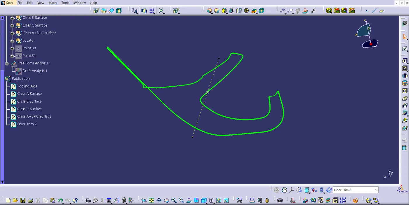
Fig 3.2
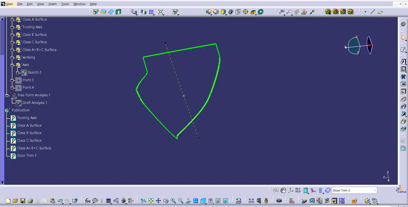
Fig 3.3
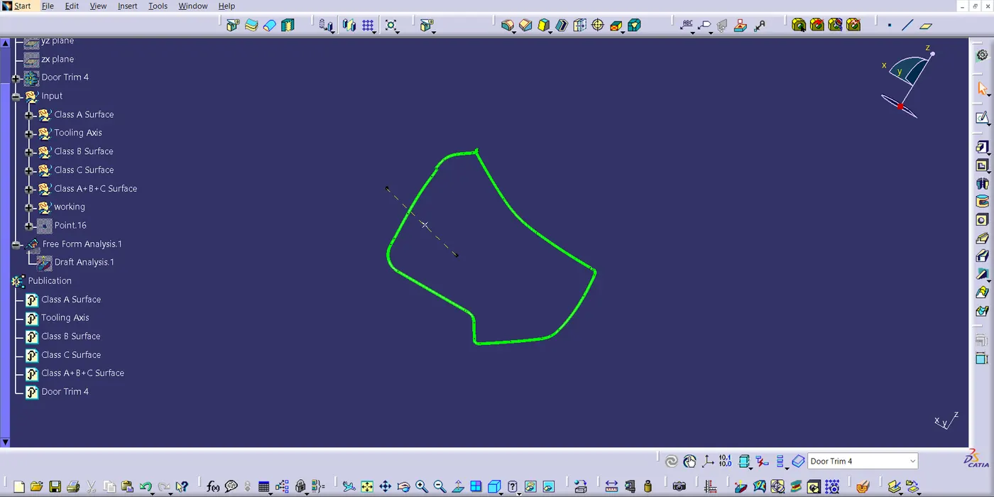
Fig 3.4
4. Closed surface and Solid parts:
The Closed part was made in order to create a solid part out of it. The Closed part was created by joining Class A, B and C Surface using Join command. The Solid part was created in Part Body workbench, using the command Closed Surface and also flanges, dog house, locators are created in the required places, then it was joined to the main body using the command Union Trim. The below mentioned figures are the closed surface and solid parts.
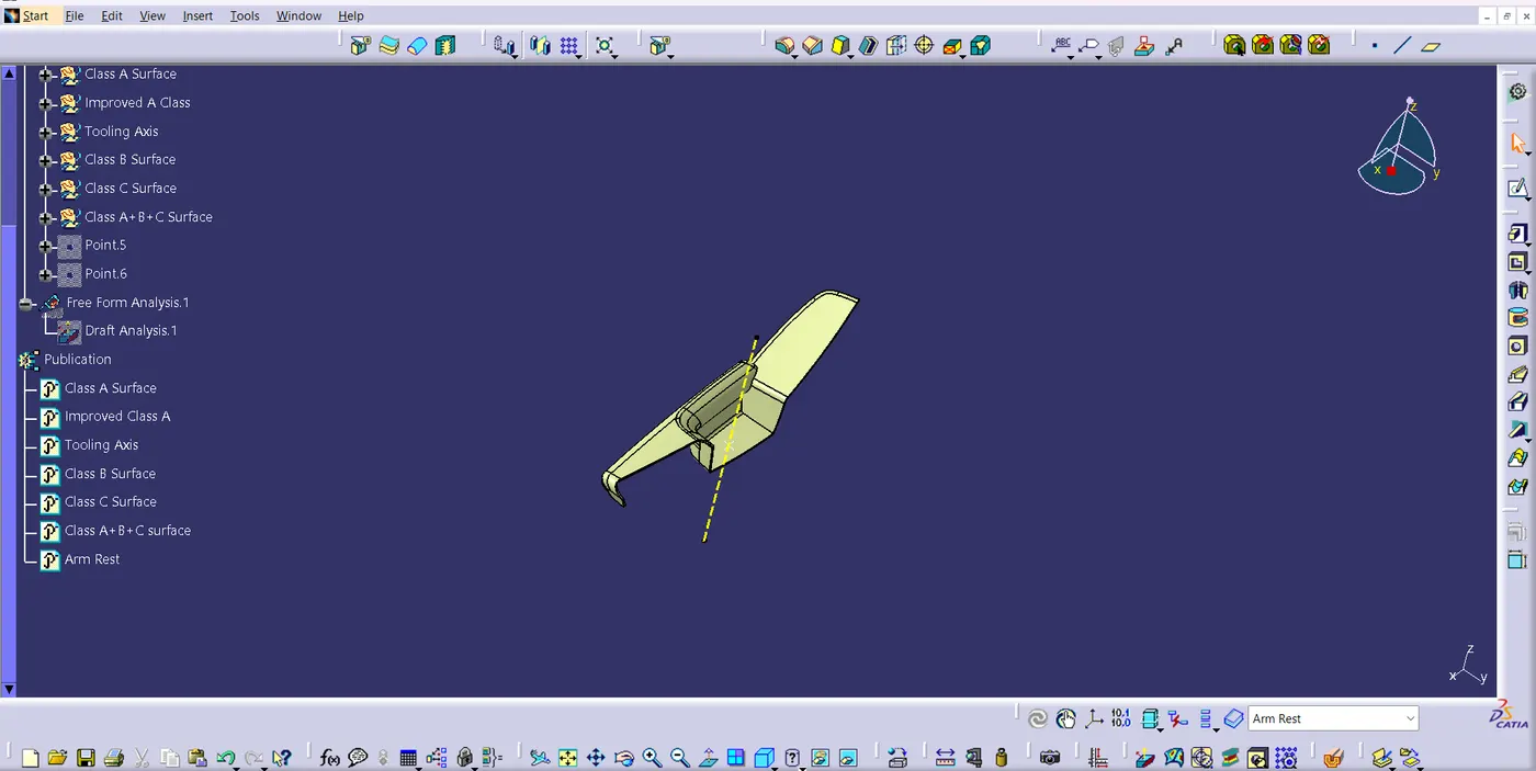
Fig 4.1
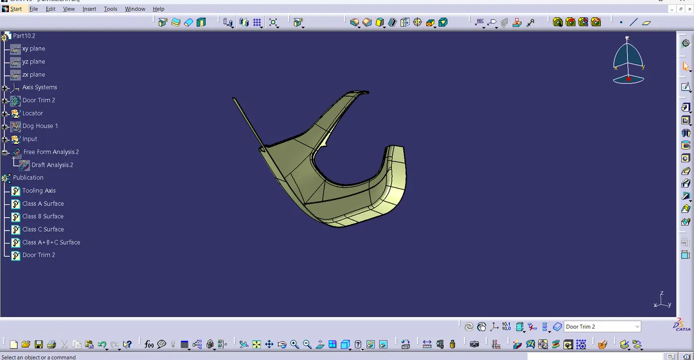
Fig 4.2
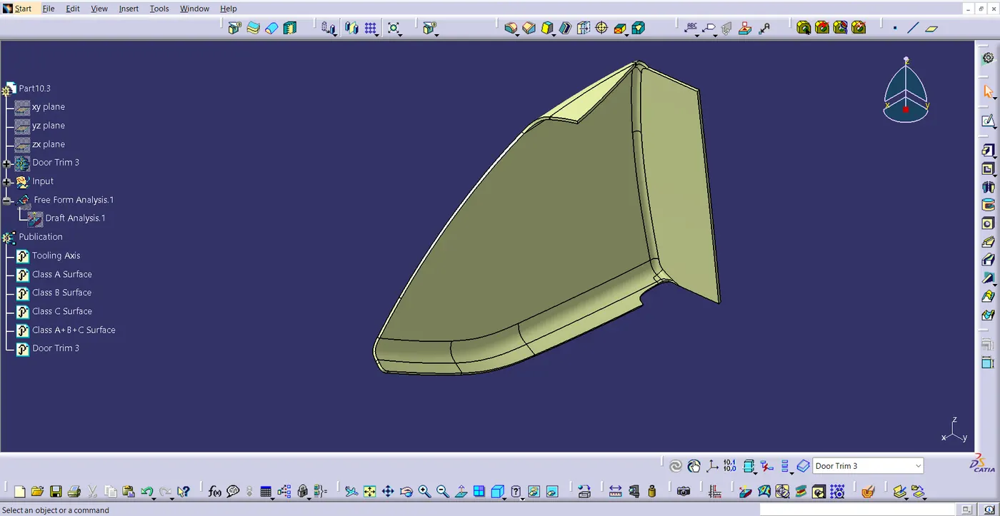
Fig 4.3
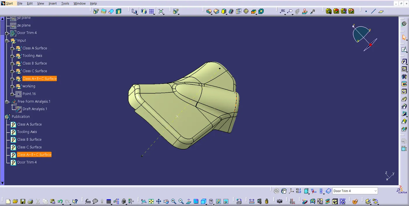
Fig 4.4
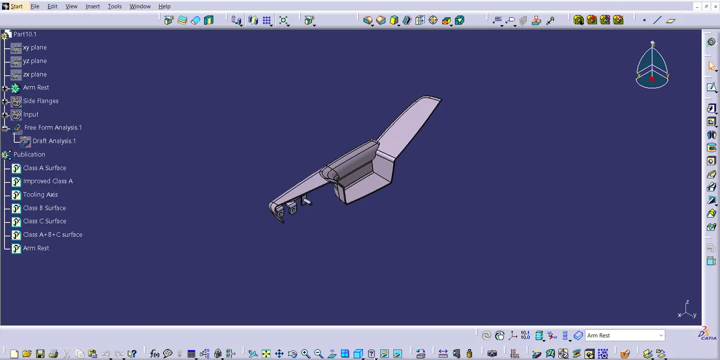
Fig 4.5
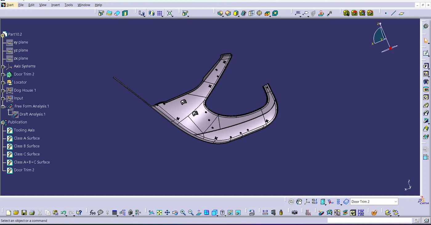
Fig 4.6
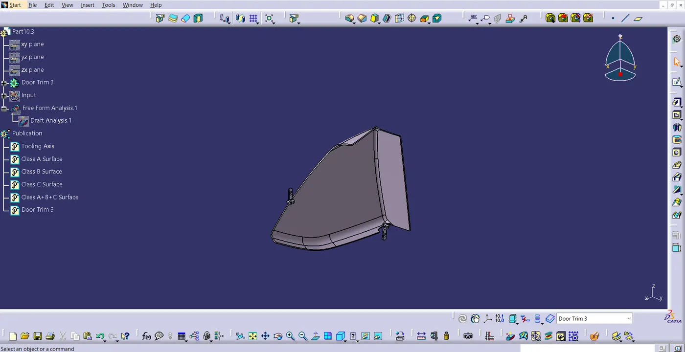
Fig 4.7
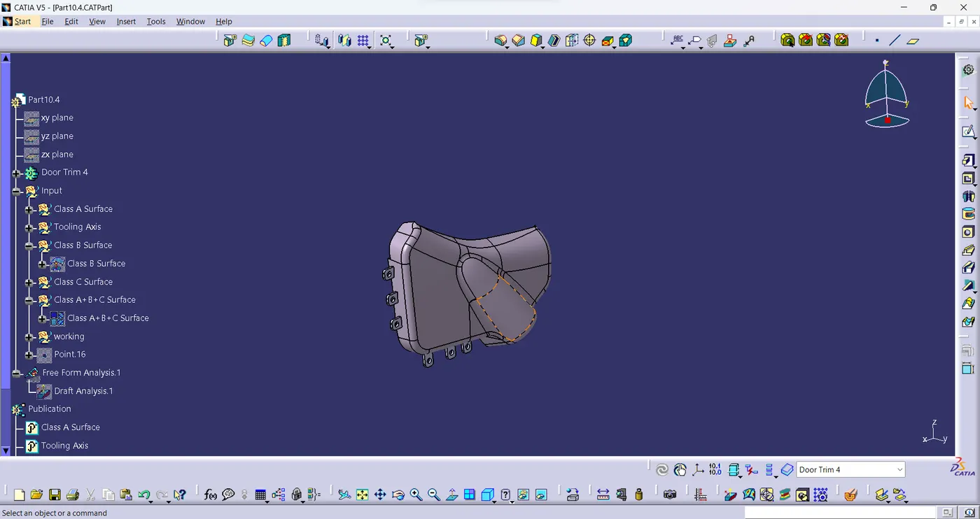
Fig 4.8
5. Draft Analysis:
A crucial step in the design process, draft analysis in CATIA V5 guarantees manufacturability and prevents problems during the production phase. Time and money are saved by detecting any issues early in the design process. The Draft analysis done using the tooling axis created at first. The term "tooling axis" refers to the feature that makes all aspects of the part easily made. Thus, in order to establish the tooling axis, we followed the steps listed, the parts-specific tooling axis was built, OEMs use many approaches for creating their tooling axes. Here, techniques like point, direction, and bisecting approach are applied. When necessary, the side core axis is also defined. Draft is done on the Class A surface. Change it to material in customise view. Click the draft analysis tool and click the surface and align the compass to tooling axis, 3 degree is the clearing angle, few sections are not clearing the draft analysis. Mentor said that it was defect in class A and it has no problem. The below images represent the draft analysis carried over the parts along with the tooling axis.
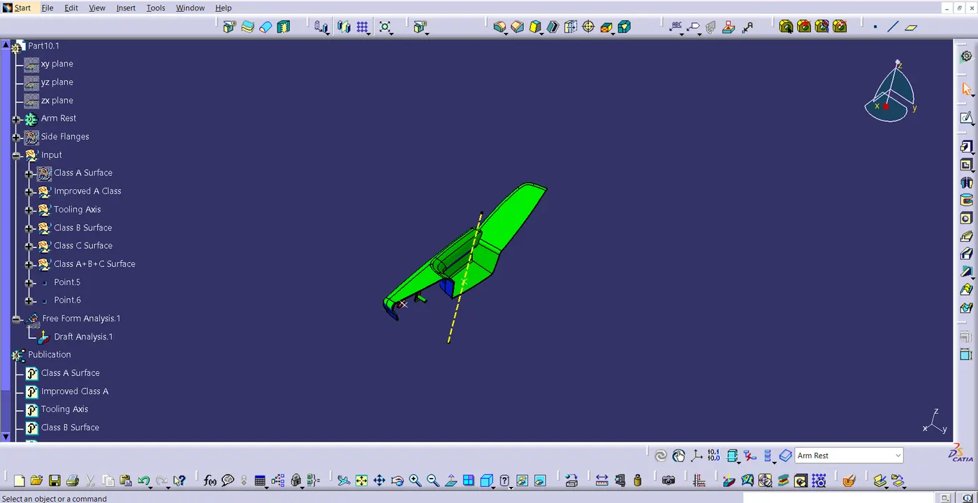
Fig 5.1
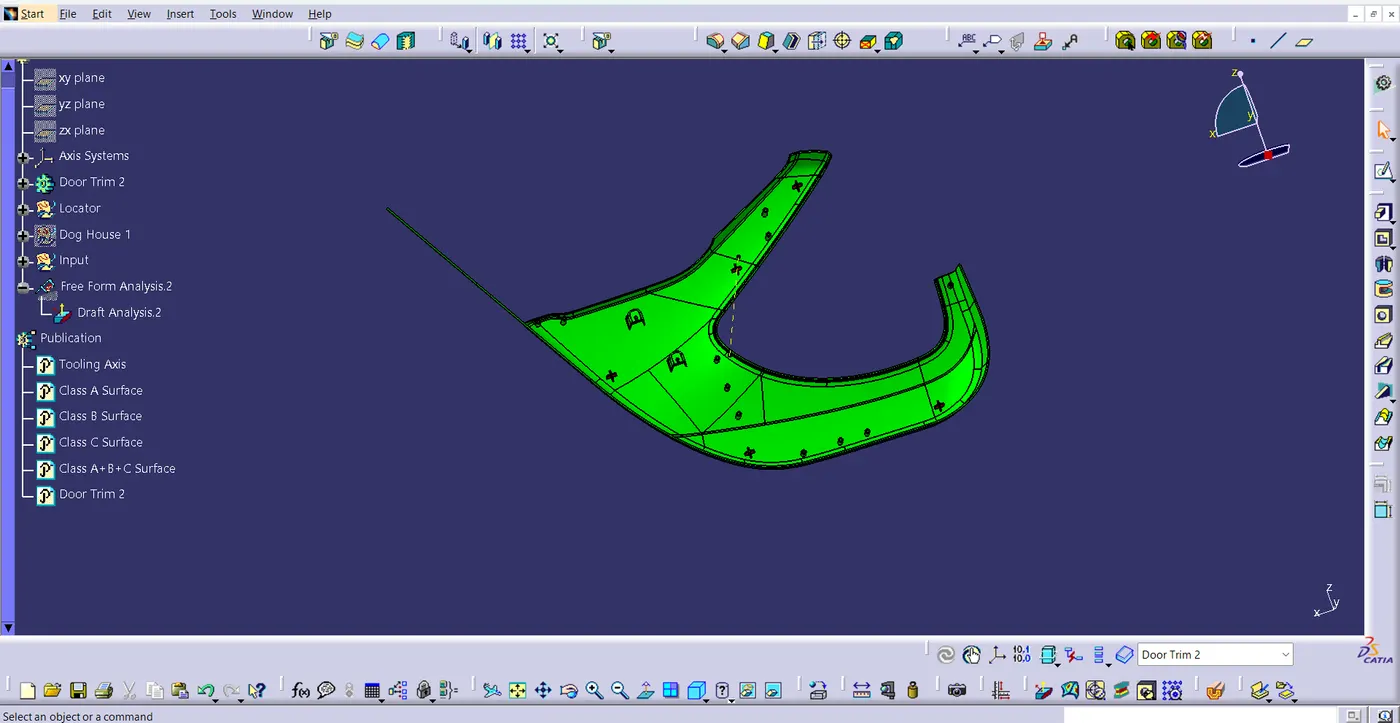
Fig 5.2
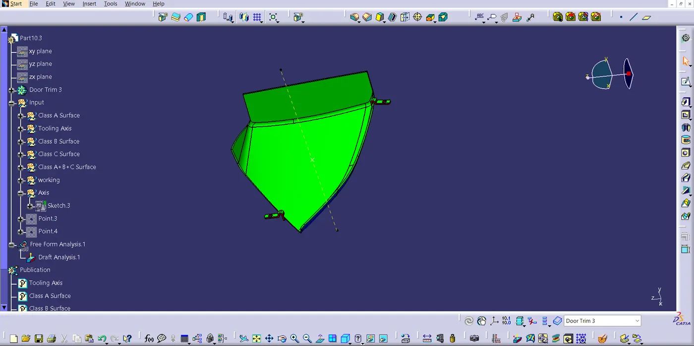
Fig 5.3
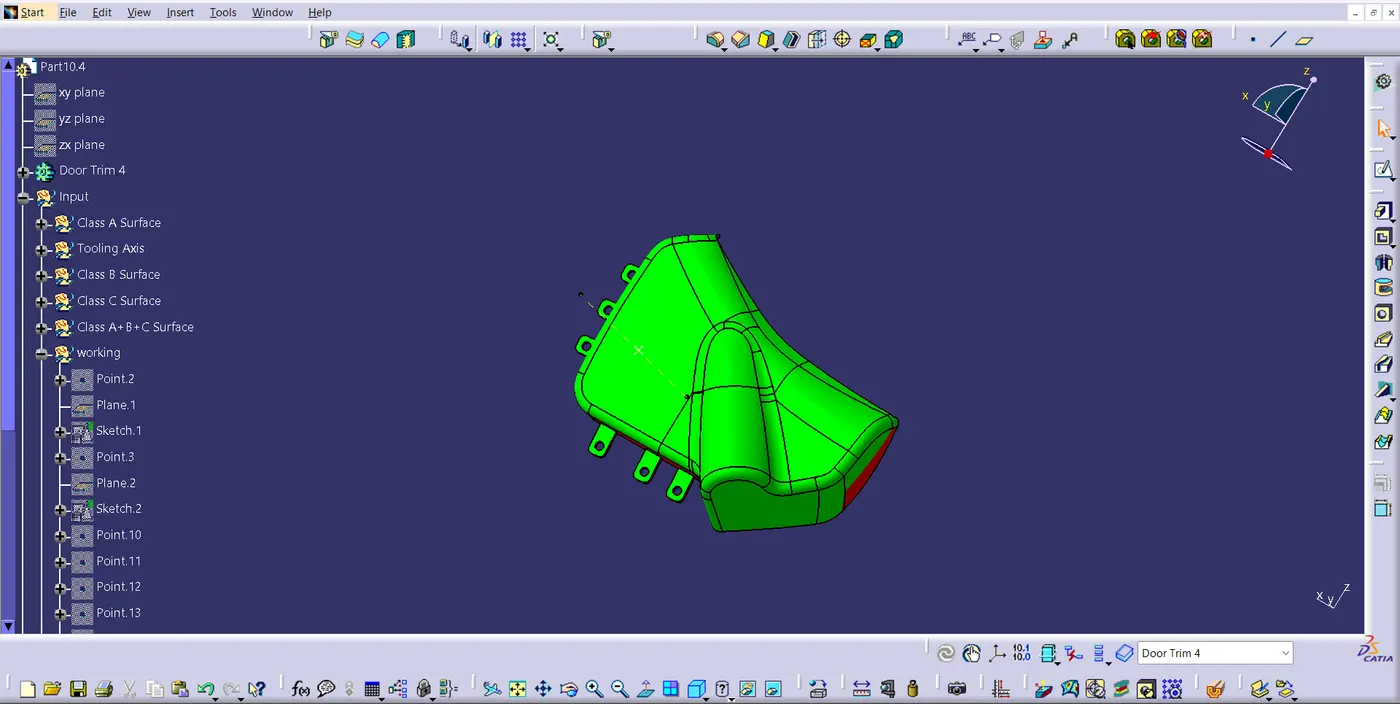
Fig 5.4
6. Final Door Trim:
After these steps, everything was assembled and the push pin is also assembled using constraints. The below images given below depicts the Final Door Trim.
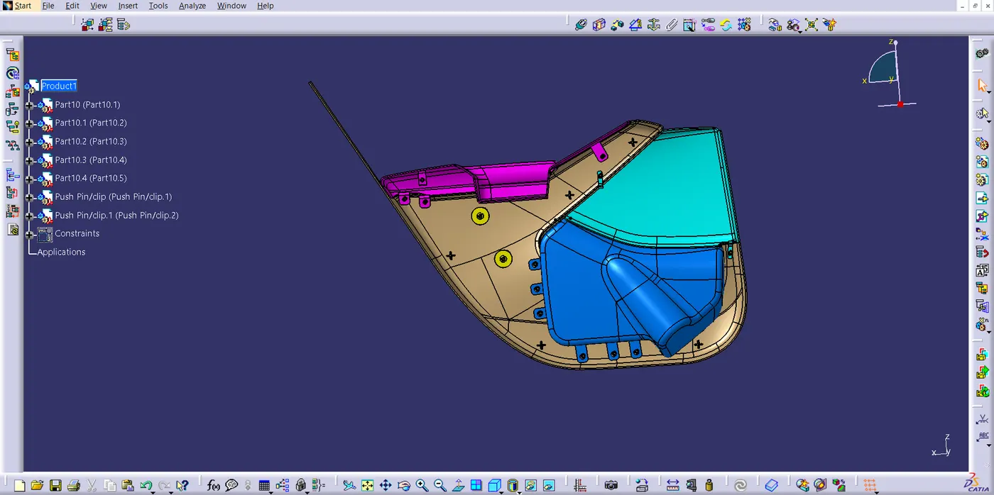
Fig 6.1. Front View
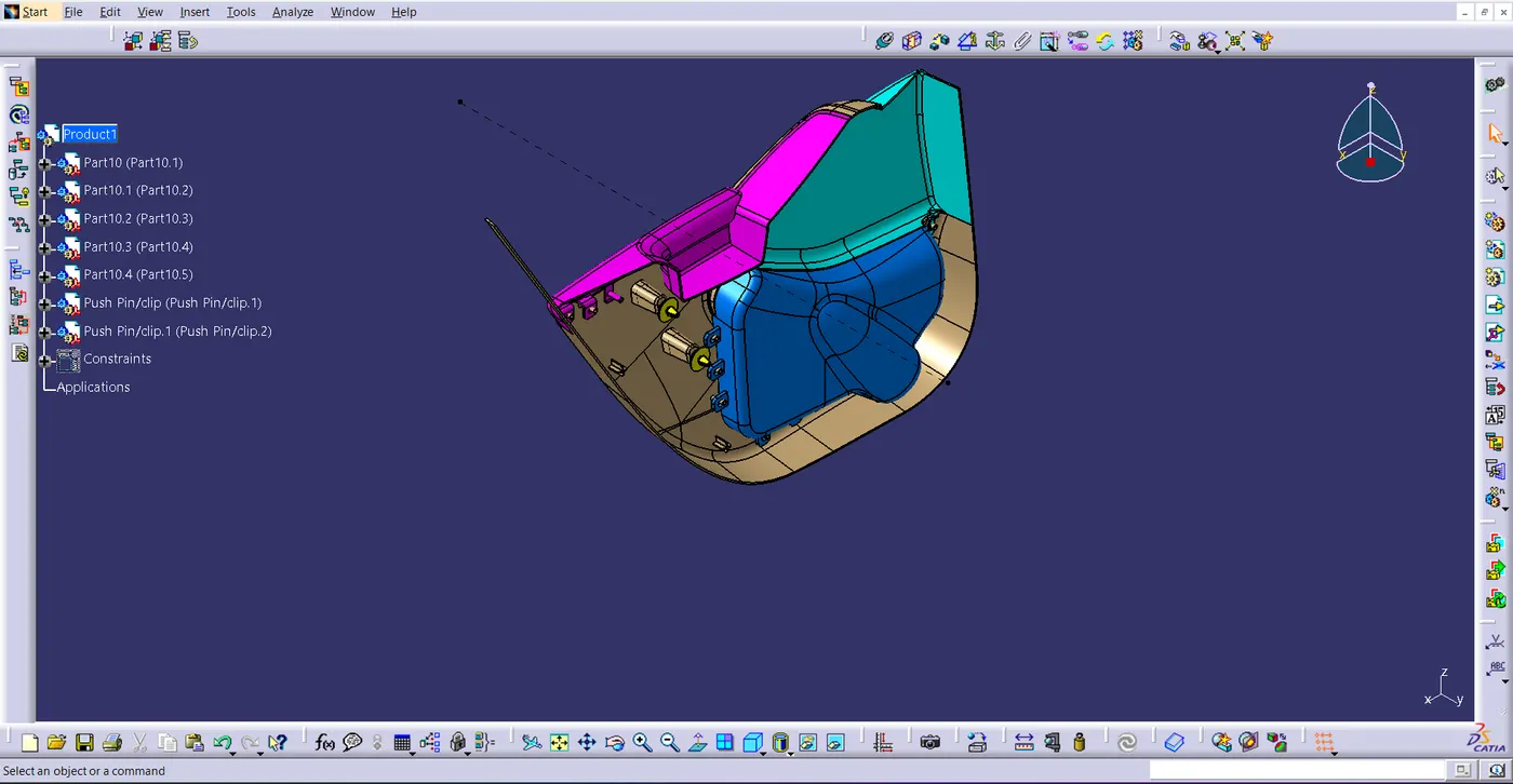
Fig 6.2. Isometric View
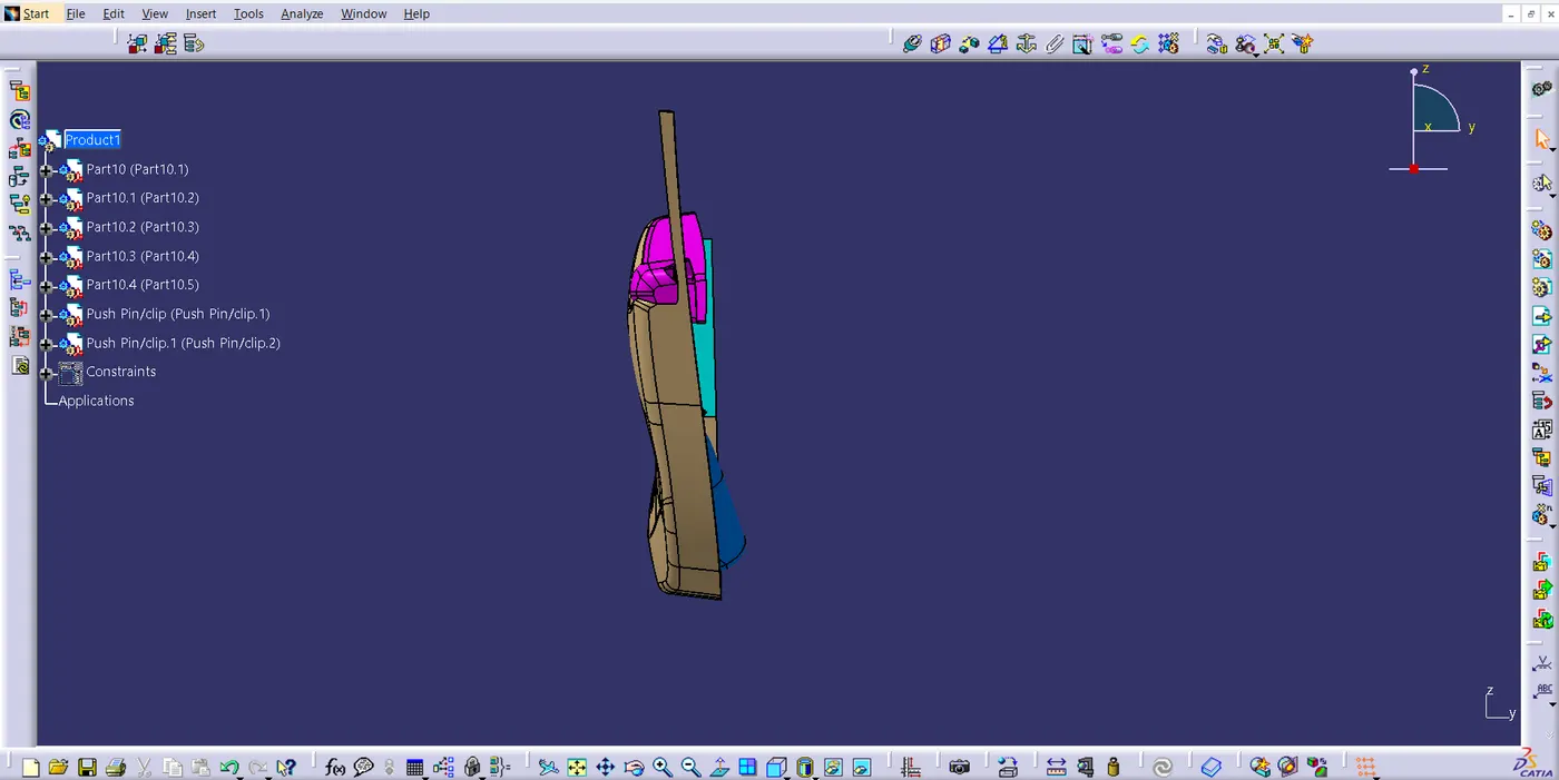
Fig 6.3. Side View I
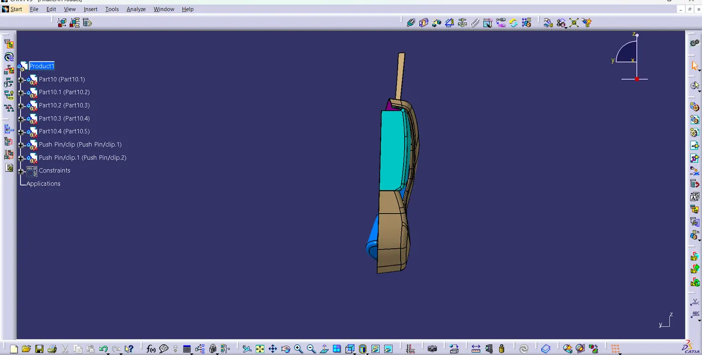
Fig 6.4. Side view II
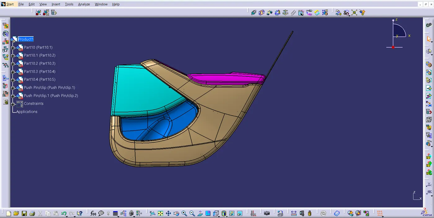
Fig 6.5. Back view
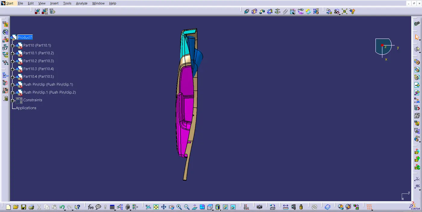
Fig 6.6. Top View
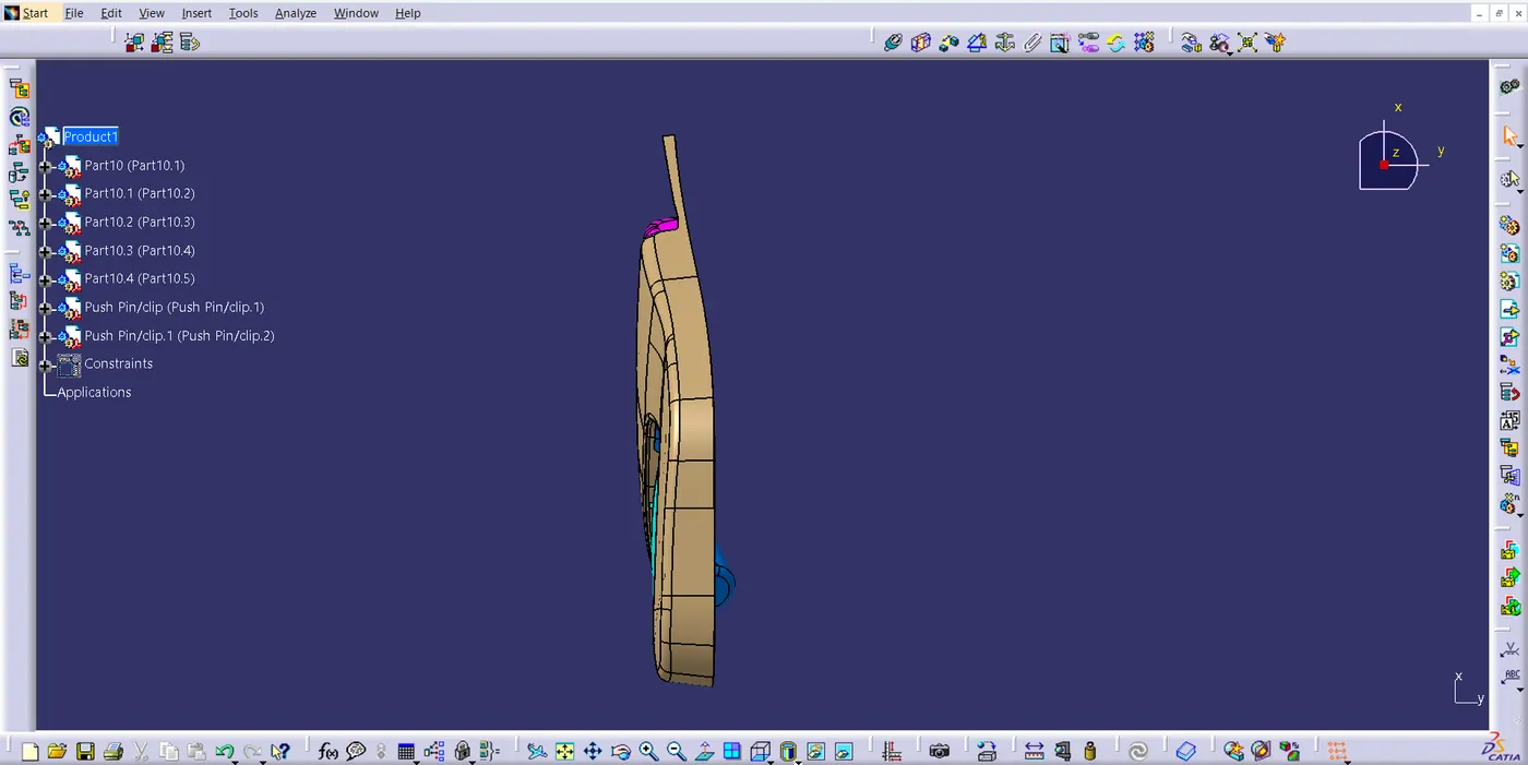
Fig 6.7. Bottom View
7. Result:
We have created the Door Trim panel using software,CATIA.