Week 12- Final project
Door trim panel is creation of CAD model considering following inputs as like in OEM and tier1 companies
Arm Rest
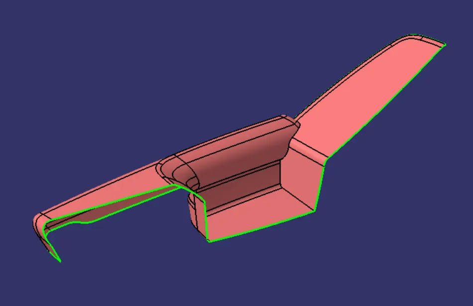
Class A surface is given but it has been found there is some improvement needed to get a closed surface. Nominal thickness is taken from the provided master sections.
Based on the knowledge that I gained from Plastic Design Course, I have develped Class B Surfaces, Class C Surfaces, tooling axis for every single part, also, four seperate parts will be assembled into one part design by creating engineering features such as Heat Stakes, Ribs, Dog Houses, Flanges and 2 way and 4 way locators.
Class A surface
Class B is created by offsetting Improved Class A by 2.5 mm as per the master section.
Class B surface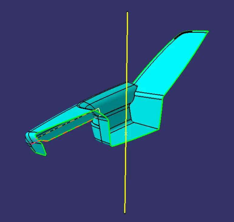
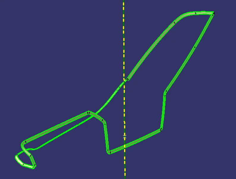
Class C is created by sweeping Improved Class A Surface and it has been trimed with Class B Surface.
Class C surface
Close Body is created from the fully close surface
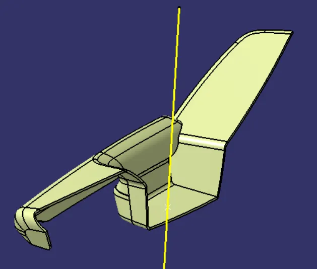
Solid Body
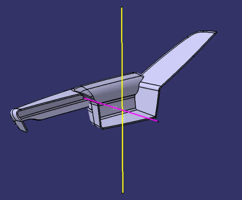
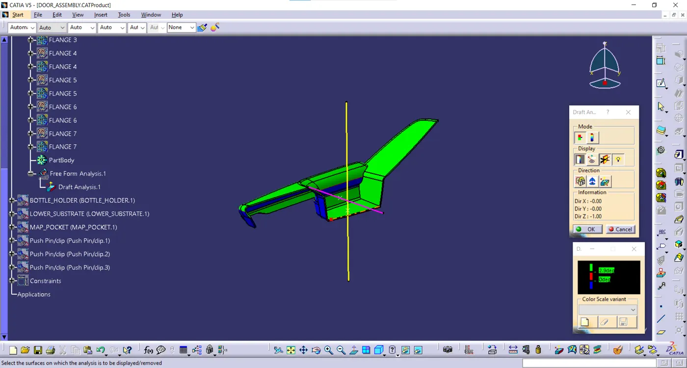
Draft Analysis:
By applying drafting analysis at 2.9 Deg, we can see most bodies have been cleared. As Green set at 2.9 degree, red set at 0 degrees and blue set at less than 0 degrees.
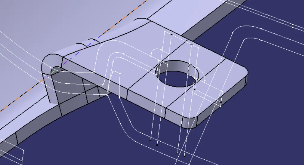
In oder to Join the Armrest body with the other bodies, I created 7 Flanges seperatly with counter holes. Then these flanges are assembled to the main body (Armrest) by union trim feature.
The vertical face of each Flange was created by extracting surface from Class C Surface. The horizontal surface is created using extrude operation and is perpendicular to vertical face. I have kept horizontal face completely flat so that it sits properly on the heat stake and it becomes easy to melt the top portion of heat stake which will stick to top horizontal face of flange providing a permanent attachment. Then I applied close surface feature to create the flange body. Also it is important to mention that the counter holes were created are iso constrained, positioned sketches and then pocket it to removed excess material from the main flange.
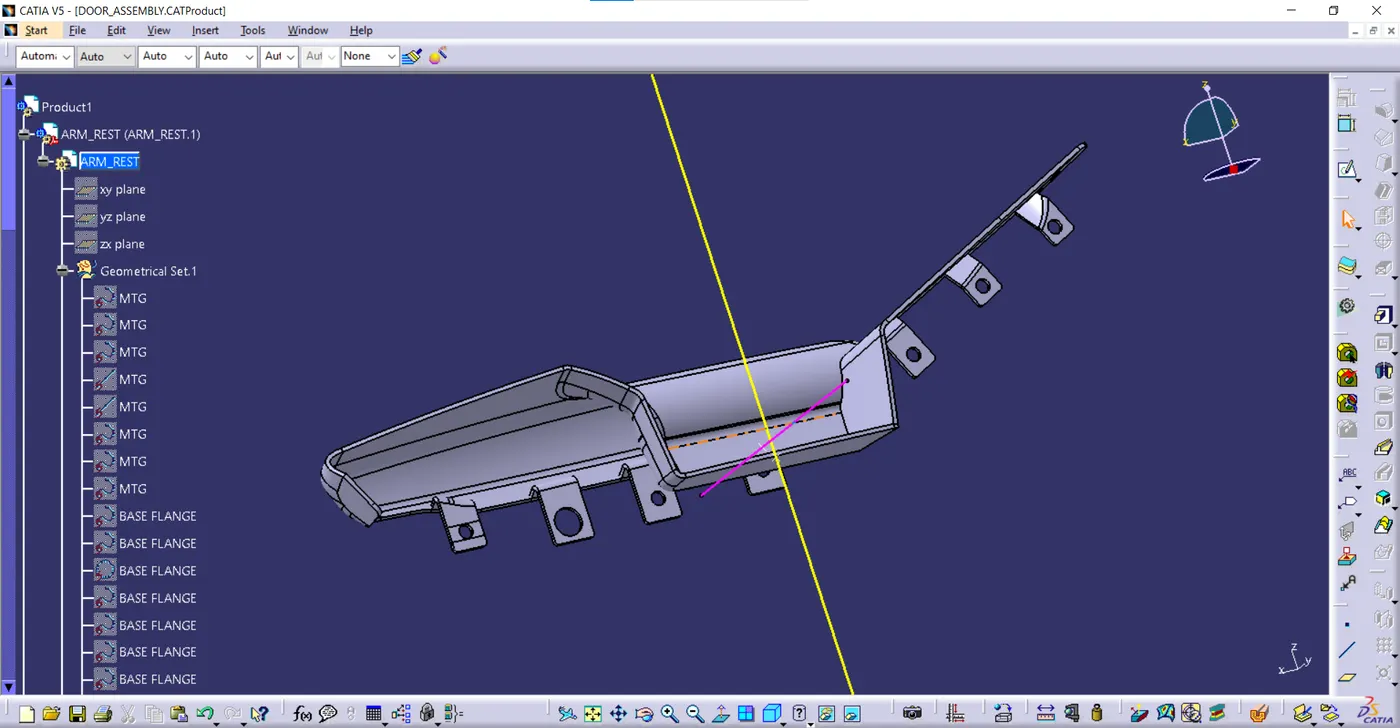
Final Armrest Body
Lower Substrate
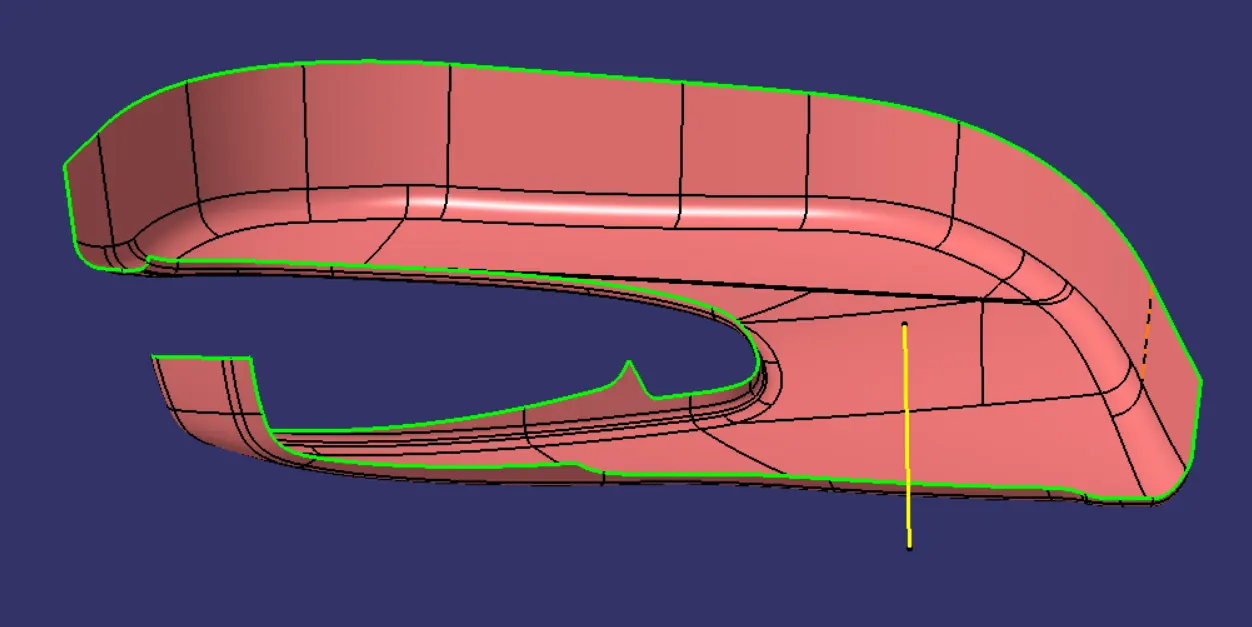
Given Class A Surface was cheked and it was found out that it was perfectly closed boundries,no further action to be taken.
Class A Surface
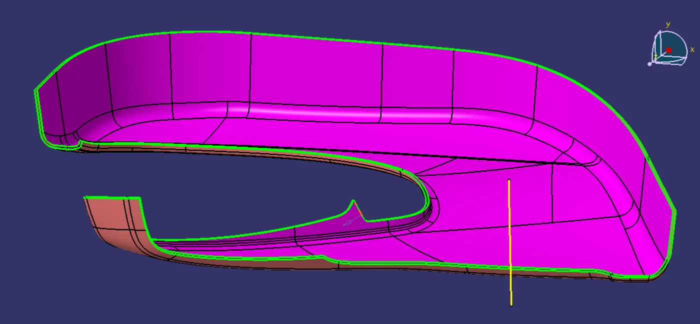
Class B is created by offsetting Class A by 2.5 mm as per the master section.
Class B Surface
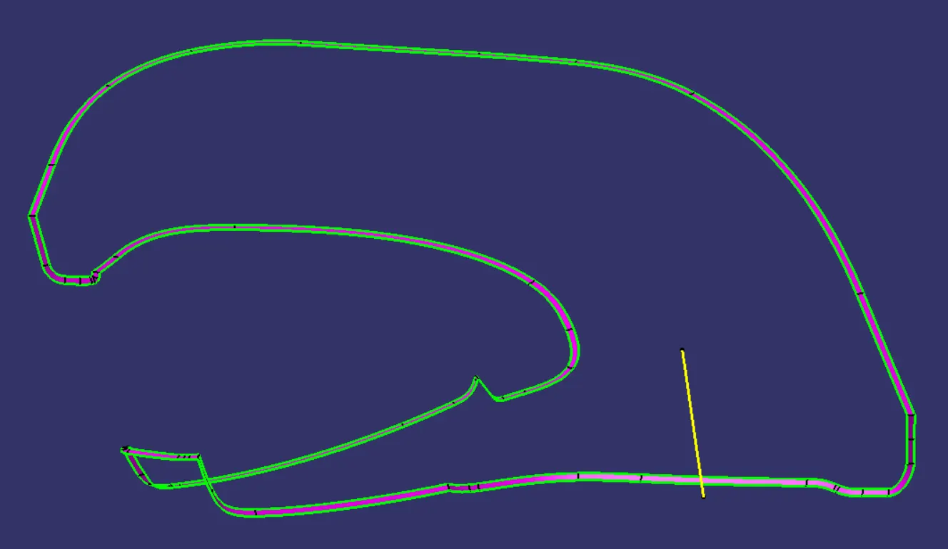
Class C is created by sweeping Class A Surface and it has been trimed with Class B Surface.
Class C Surface
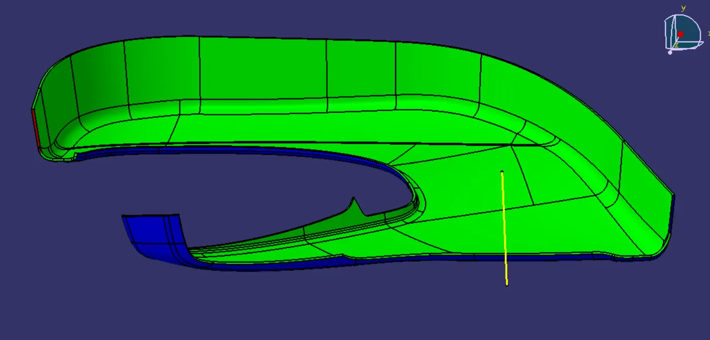
Draft Analysis:
By applying drafting analysis at 2.9 Deg, we can see most bodies have been cleared. As Green set at 2.9 degree, red set at 0 degrees and blue set at less than 0 degrees.
In order to Join the Lower Sustrate with the other bodies, I have created 13 heat satkes to attach lower substrate with other components. Apart from this i have created a 2 way locator and a 4 way locator which will be used along with heat stakes to arrest all 12 degres of freedom. I have also created 2 dog house which will be used as the housing for push pins. All connecting engineering features are created attched to this body while flanges will be conecting this main body to other bodies.
Draft analysys on 2 way locator
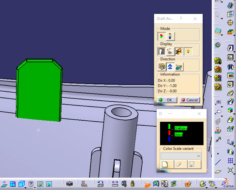
Draft analysys on 4 way Locator
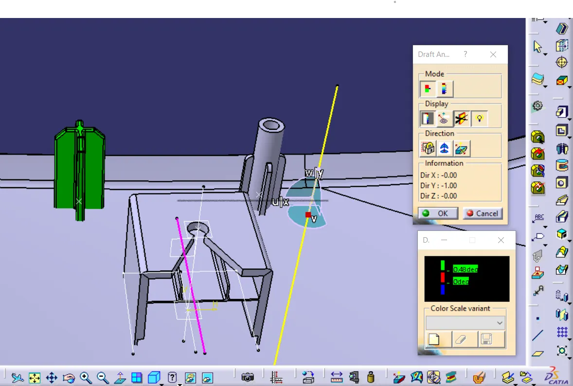
Draft analysys on Heat Stake
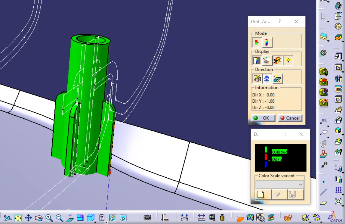
Draft analysys on Dog House Using Main Tooling Axis
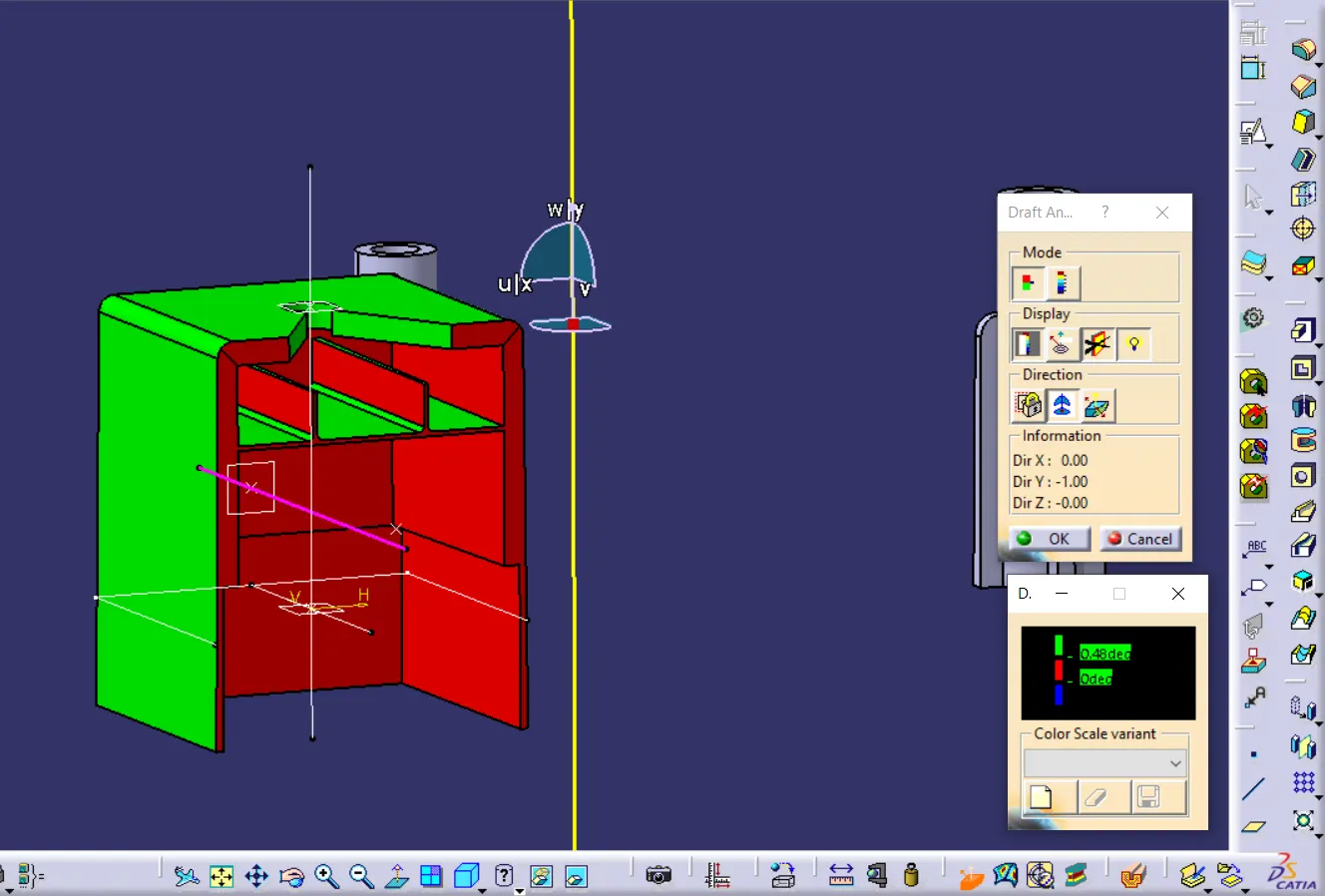
Draft analysys on Dog House using Side Core Axis
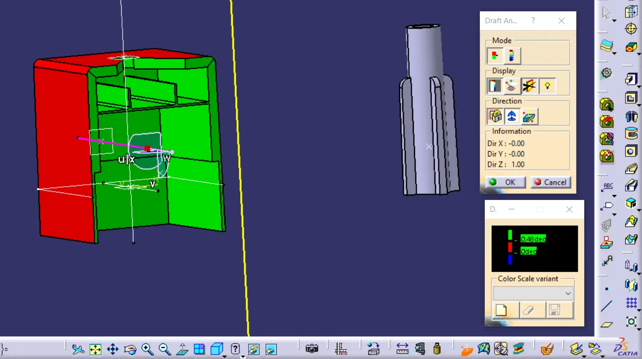
Final Lower Substrate Body
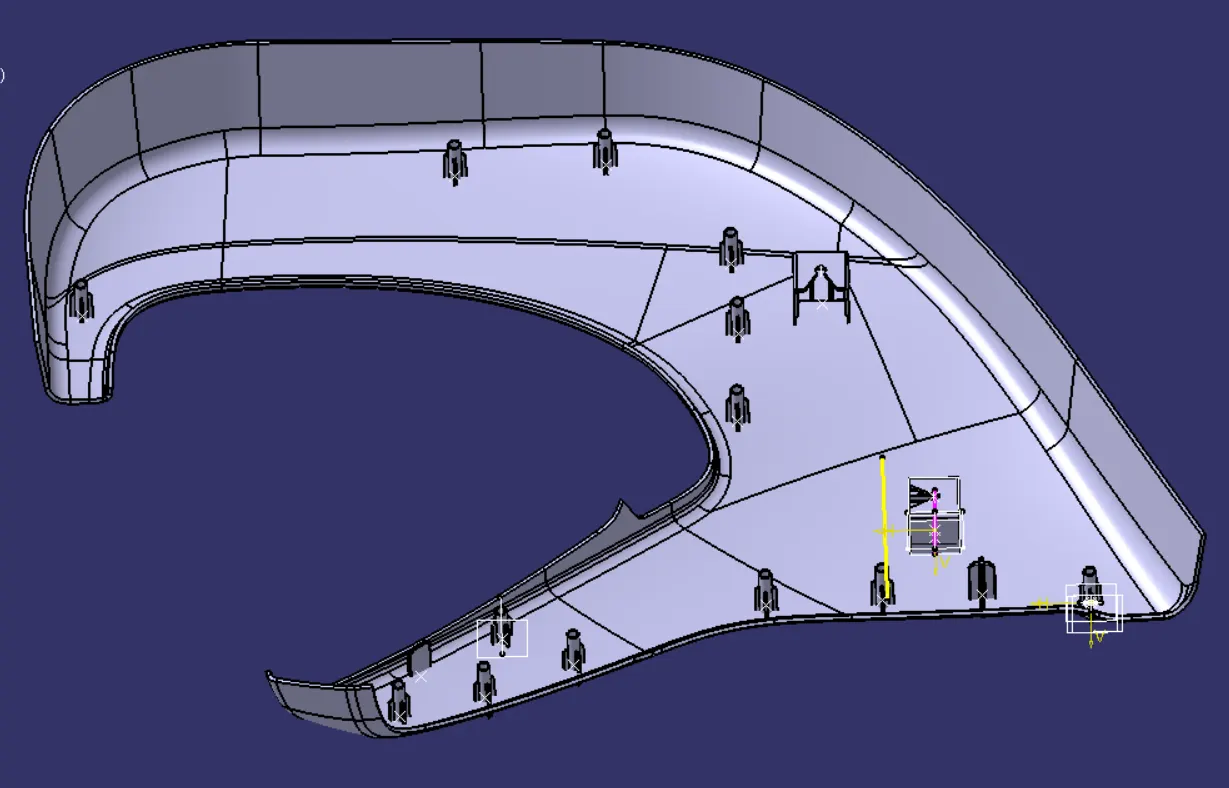
Map Pocket
Given Class A Surface was checked and found out it is perfectly closed boundries, no further action to be taken.
Class A Surface
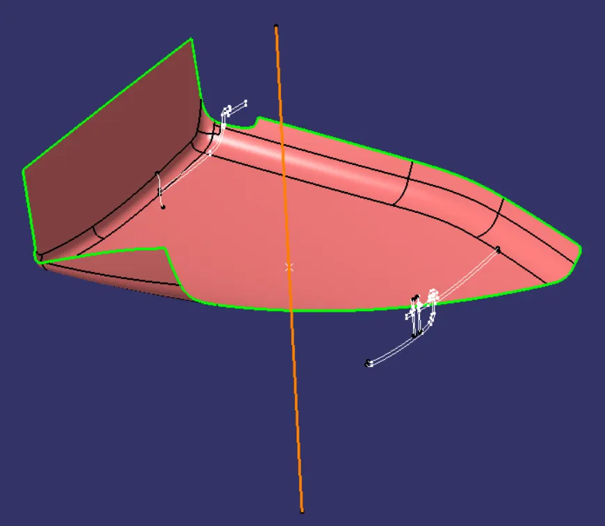
Class B is created by offsetting Class A by 2.5 mm as per the master section.
Class B Surface
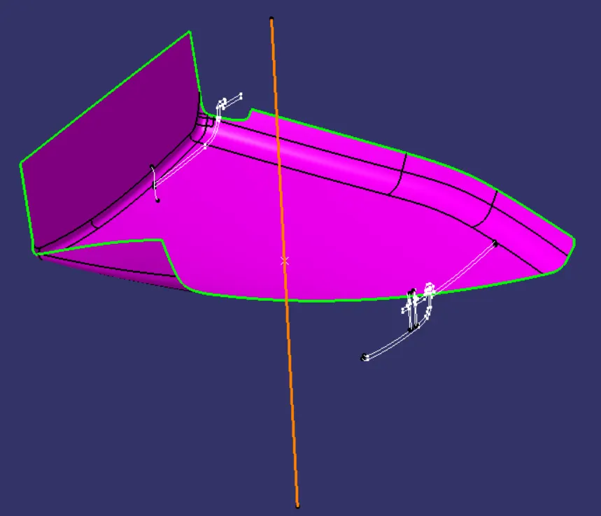
Class C is created by sweeping Class A Surface and it has been trimed with Class B Surface.
Class C Surface
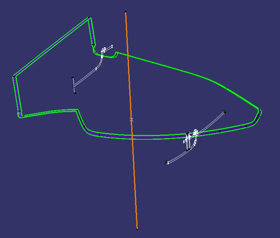
Final Closed Surface
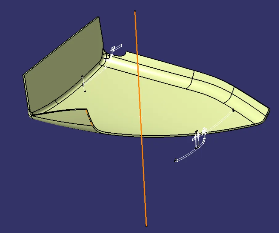
Final Body
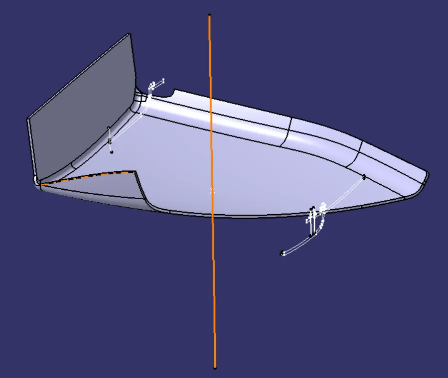
Draft Analysys
By applying drafting analysis at 2.9 Deg, we can see most bodies have been cleared. As Green set at 2.9 degree, red set at 0 degrees and blue set at less than 0 degrees.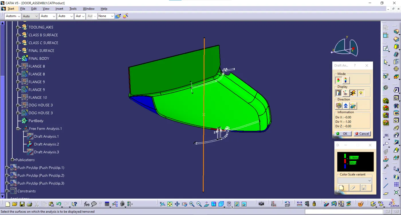
In order to Join the Map Pocket with the other bodies, I created 2 Flanges seperatly with counter holes, Flanges are different based on the engineering features that will be assembled with them. Then these flanges are assembled to the main body (Map Pocket) by union trim feature.
The vertical face of each Flange was created by extracting surface from Class C Surface. The horizontal surface is created using extrude operation and is perpendicular to vertical face. I have kept horizontal face completely flat so that it sits properly on the heat stake and it becomes easy to melt the top portion of heat stake which will stick to top horizontal face of flange providing a permanent attachment. Then I applied close surface feature to creat the flange body. Also it is important to mention that the counter holes were created by iso constrained, positioned sketches and then pocket it to removed excess material from the main flange.
I have also created a Dog House to support push pin which will attach the entire structure to sheet metal.
Draft analysys on Dog House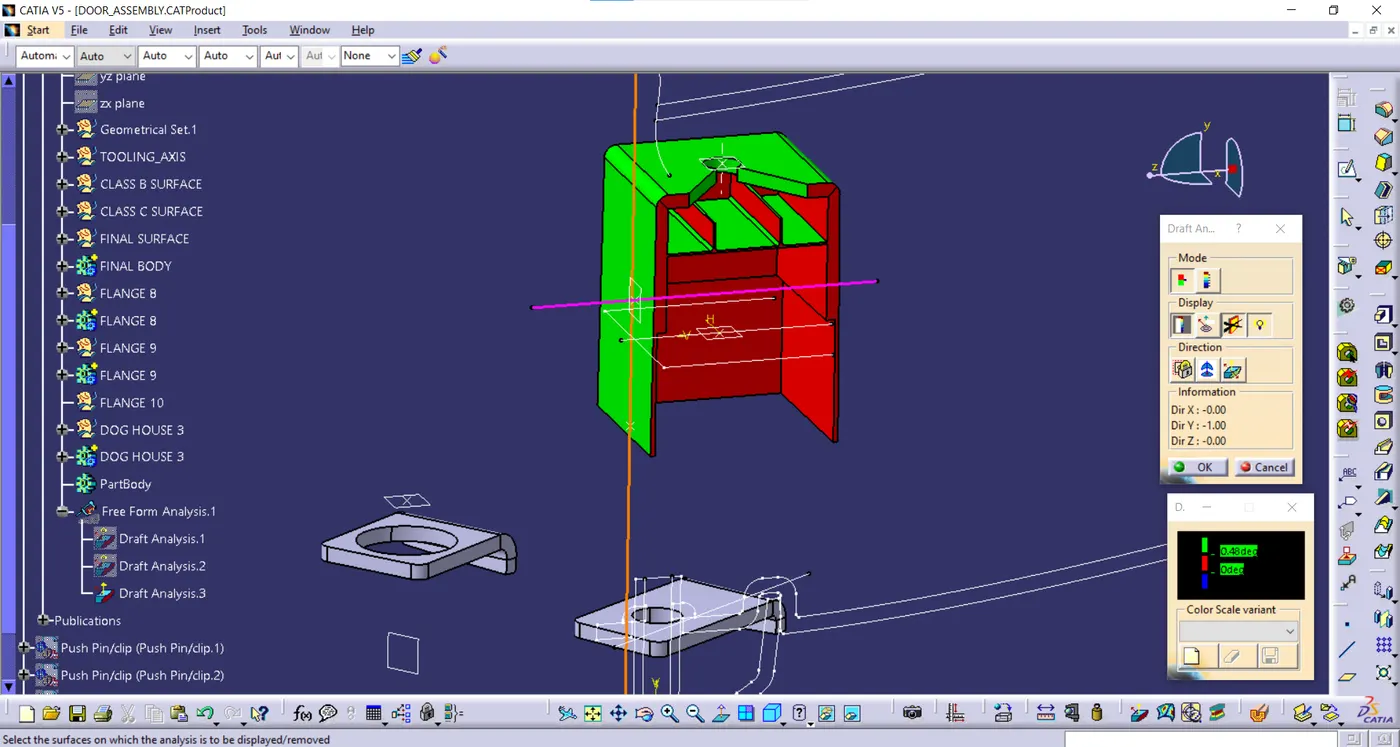
Final Map Pocket Body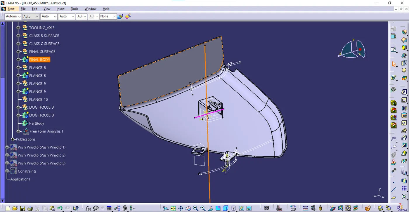
Bottle Holder
Class A Surface
Given Class A Surface was checked and found out it is perfectly closed boundries, no further action to be taken.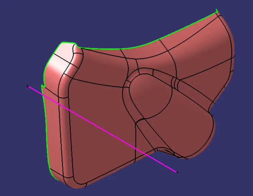
Class B is created by offseting Improved Class A by 2.5 mm as per the master section.
Class B Surface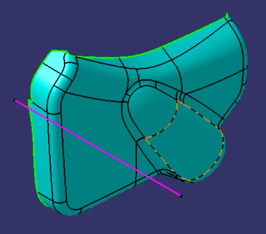
Class C is created by sweeping along Class A Surface and it has been trimed with Class B Surface.
Class C Surface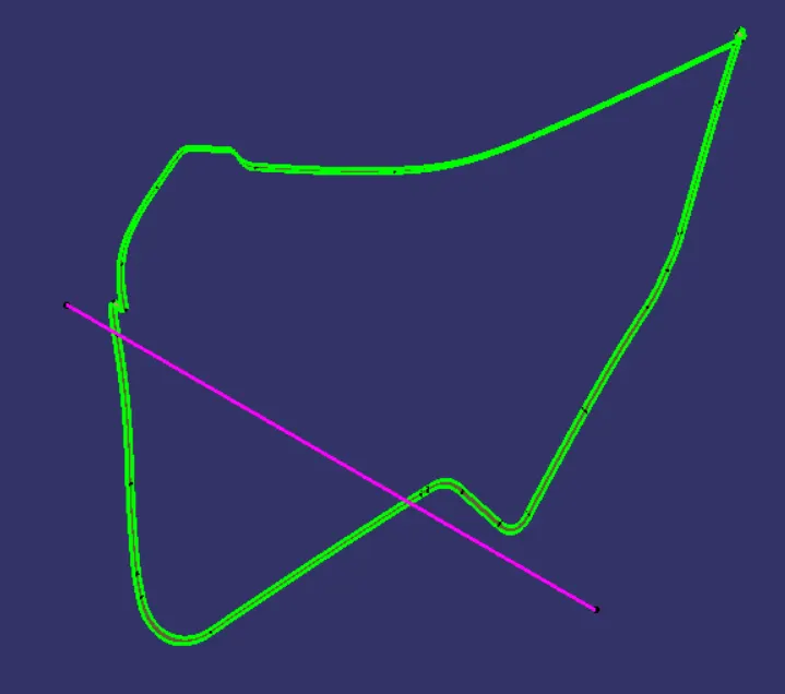
Final Closed Surface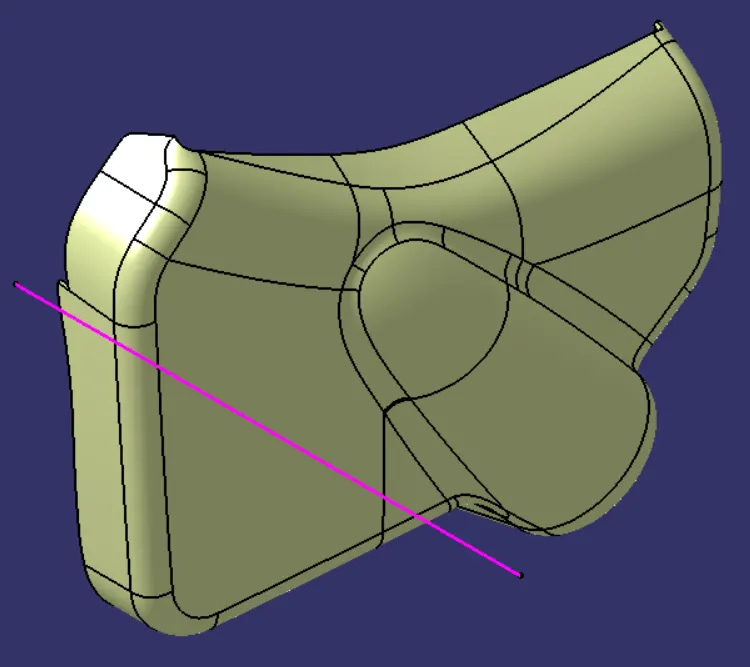
Solid Body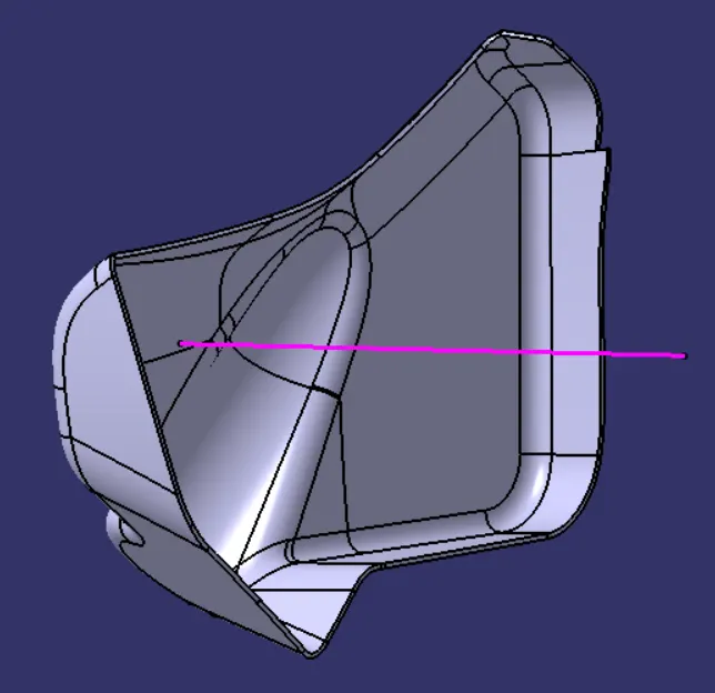
Draft Analysys
By applying drafting analysis at 2.9 Deg, we can see most bodies have been cleared. As Green set at 2.9 degree, red set at 0 degrees and blue set at less than 0 degrees.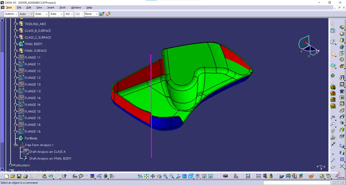
In order to Join the Bottle Holder with other components, I created 6 Flanges seperatly with counter holes, Flanges are different based on the engineering features will be assembeled with them. Then these flanges are assembled to the main body (Map Pocket) by unitrim feature.
The vertical face of each Flange was created by extracting surface from Class C Surface. The horizontal surface is created using extrude operation and is perpendicular to vertical face. I have kept horizontal face completely flat so that it sits properly on the heat stake and it becomes easy to melt the top portion of heat stake which will stick to top horizontal face of flange providing a permanent attachment. Then I applied close surface feature to create the flange body. Also it is important to mention that the counter holes were created are iso constrained, positioned sketches and then pocket it to removed excess material from the main flange.
Final Map Pocket Body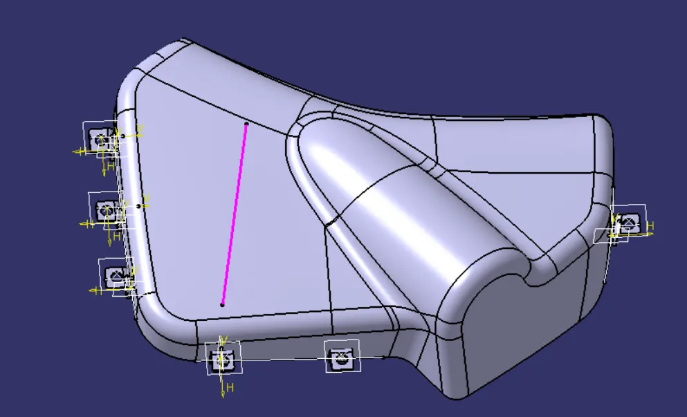
Parting Lines
ArmRest Lower Substrate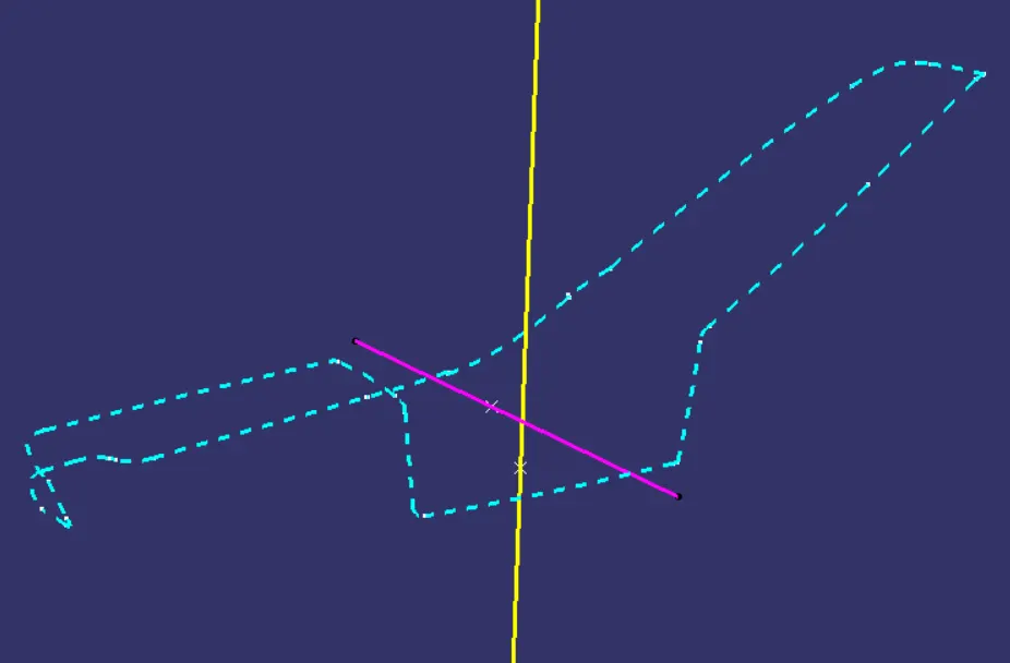
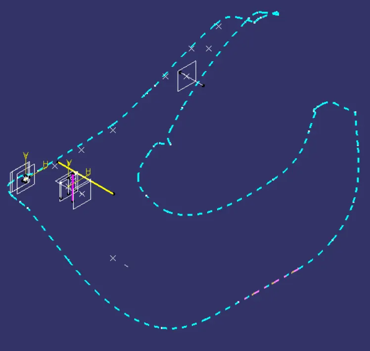
Bottle Holder Map Pocket
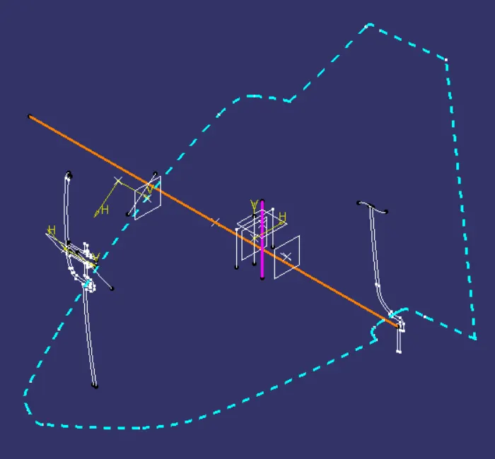
Push Pins
As I have created 3 Dog Houses for this part assembly, i need to inport 3 Push pins. All 3 push pins assembly is shown below: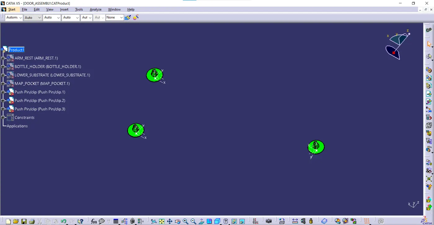
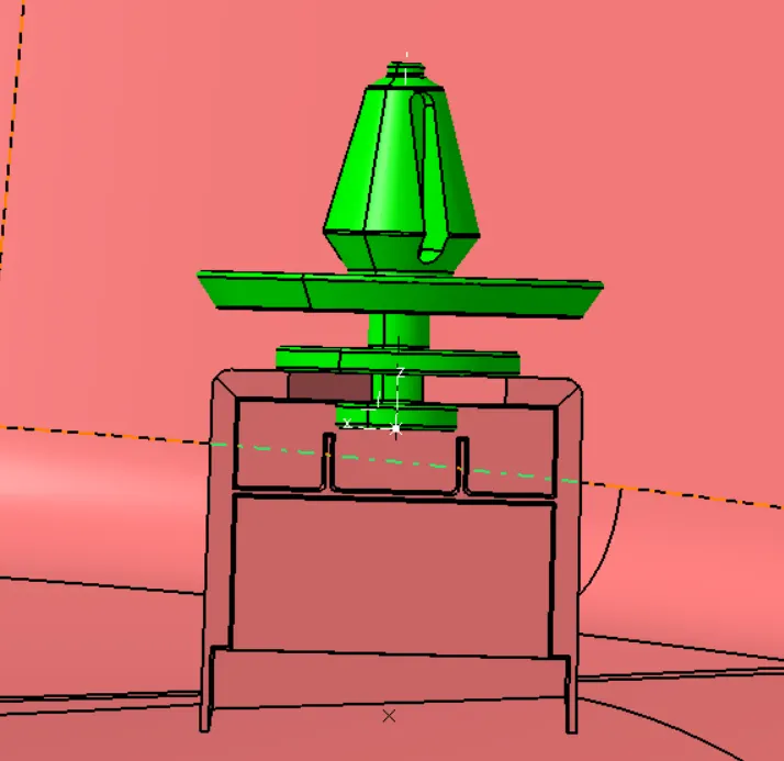
Below figure shows how pushpin is being attached to dog house. Lower portion is attached to dog house and upper portion will be attached to sheet metal. Hole is made at center in the top face of dog house using which push pin gets snap fit in the dog house.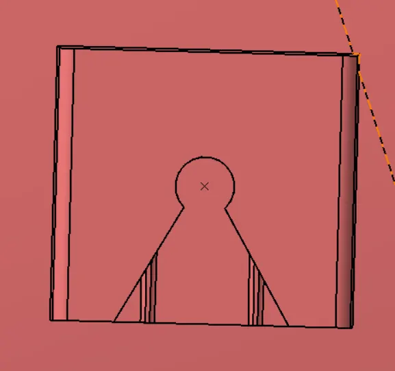
Different Veiws of Entire Assembly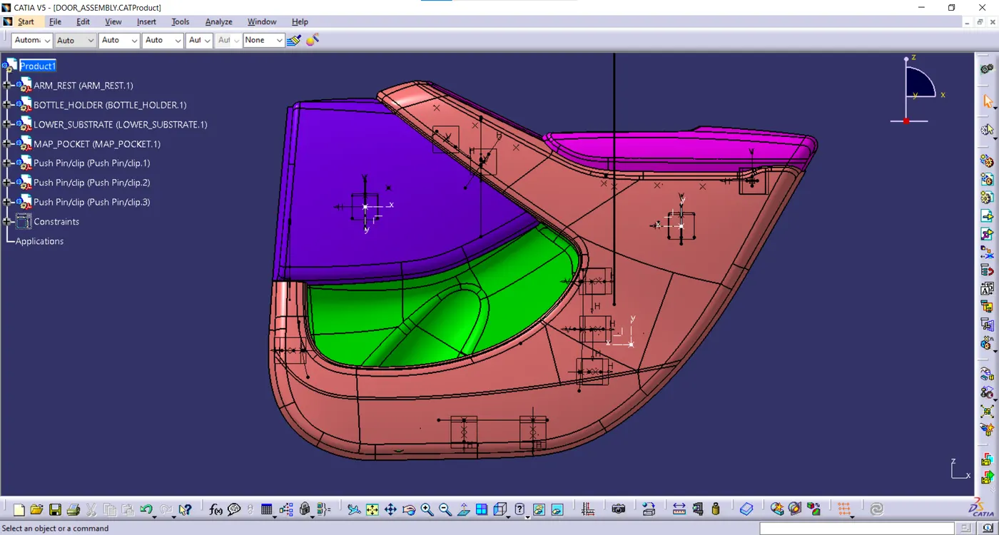
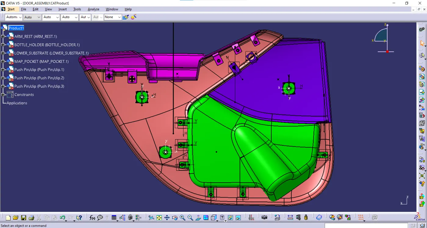
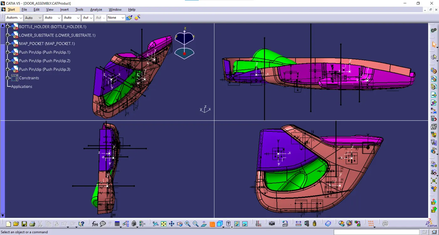
The CATpart and CATproduct are submitted in the attachment.