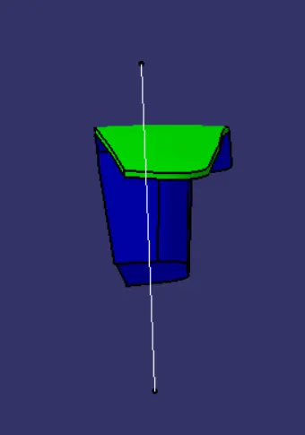
Week 8 - Challenge 2 - Switch Bezel Design
Aim
Create the Switch Bezel Plastic component through the given Class - A surface
Objective
The objective of the project is to design the switch bezel and to do a draft analysis for it by creating the required tooling direction with the help of Bisecting method
Introduction
The control panel bezel is the frame part of the window switch that holds its switch covers and buttons into a place. moulding is the method used to manufacture the plastic trims of an automotive by most OEM's hence by considering the manufacturing consideration the switch bezel is designed.
Design Consideration
1. Class - A surface should be aesthetically smooth and good.
2. Class - B surface should have all the supporting features like ribs.
3. Parting line should coincide with the B surface since flashing couldn't affect the aesthetic of Class - A.
4. Class - C surface should also pass the draft analysis.
Creation of Tooling Direction
1. considering the ejection from the cavity of the mound after manufacturing the interior trim(switch bezel0 must have the nominal 3- degree draft angle
2. Hence the tooling direction is created by considering the above factor and bisecting method is used.
3. The base surface of the class - A was extracted and a point at the centre is created and an axis system was inserted to the point with the current feature is disabled.
4. Then,usingproject intersection along yz plane is created and the two inclined lines were drawn inside the positioned sketch.
5. Then bisecting lines with the two iclined lines were drawn
6. Now thw same procedures is done along the xz plane but on one side we don't have iclined lines so the centre point is used to extrude a line along the z- direction and gave a measurement of 5 degree (Tentatively).
7. With these two lines frm sketches 1 and 2, the bisecting line is created and published as tooling axis( tooling direction)
Draft Analysys
Draft analysys on final body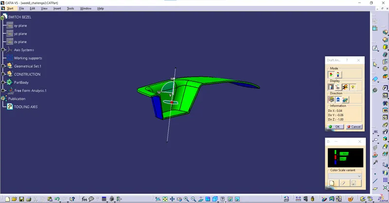
The post part raft analysis shows some red that is zero to 3 degree draft, hence the draft was reduced to 2.9 degree which resulted in less red edges. Rest part was shown green which is safe for ejection of the part.
Draft analysys on class A
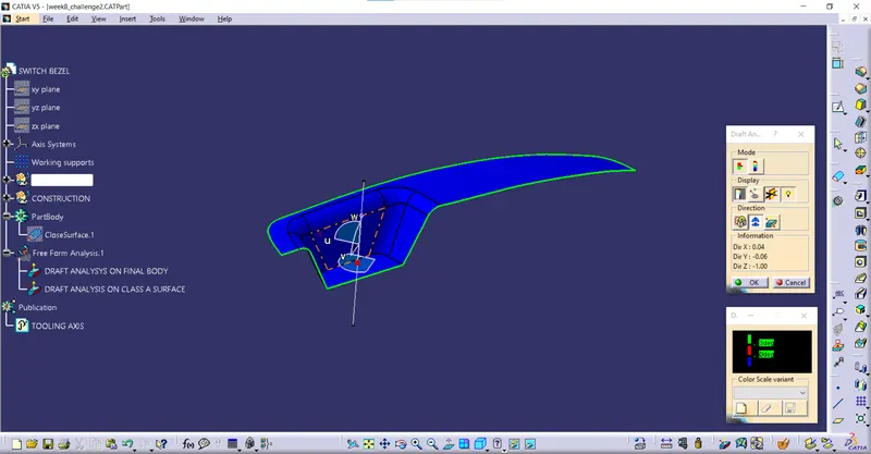
Class A
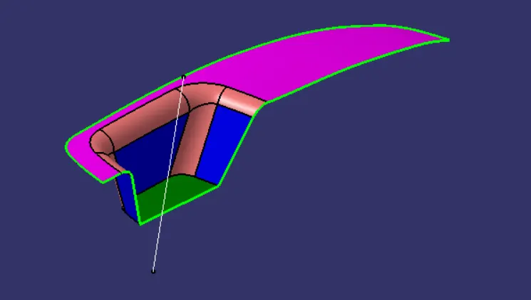
Class B
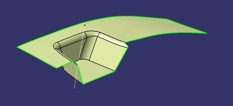
Class C
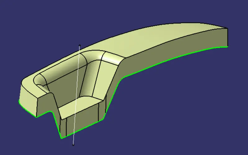
Final Solid body
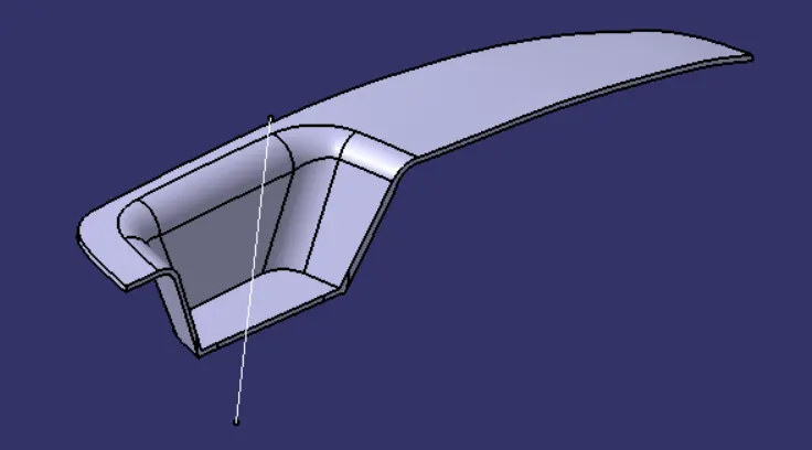
Isometric View
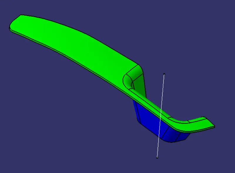
Front View
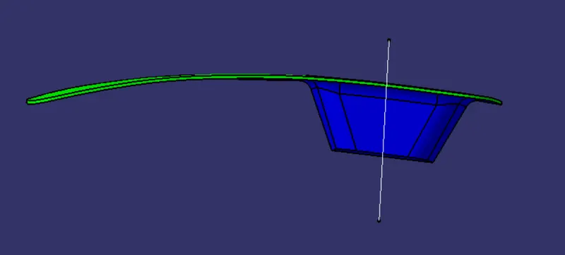
Top View
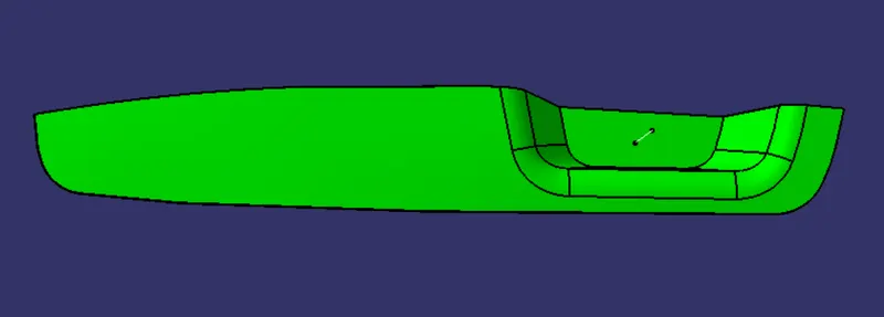
Side View