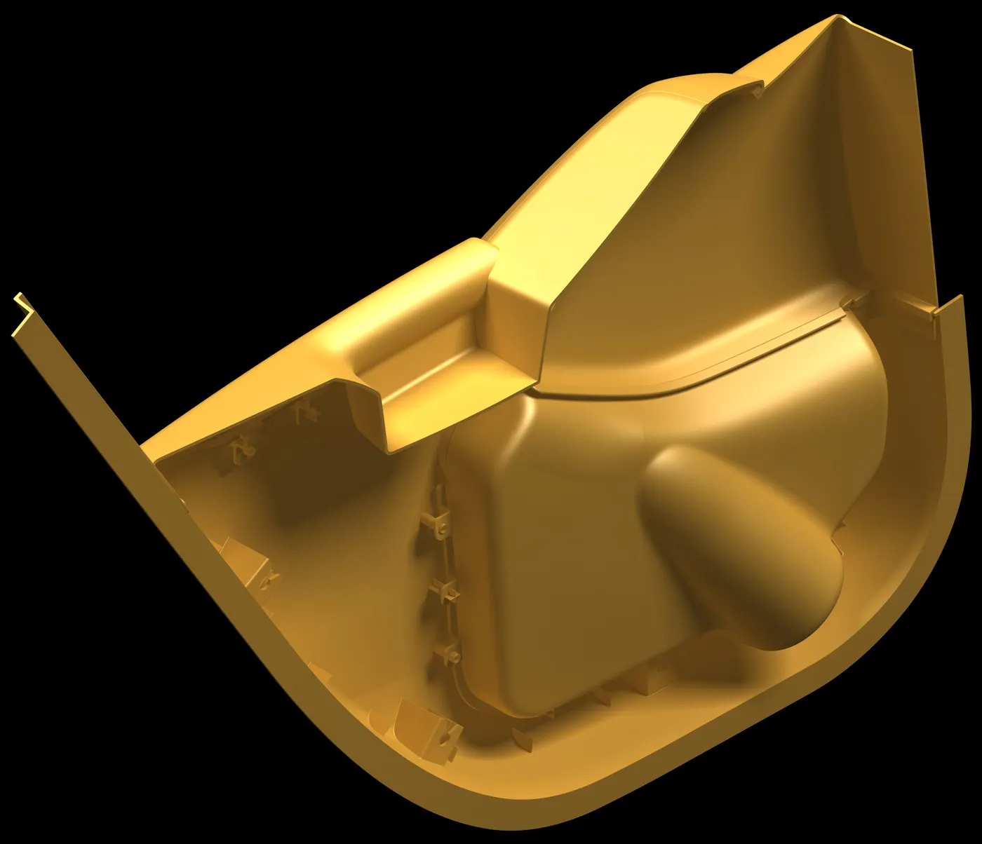
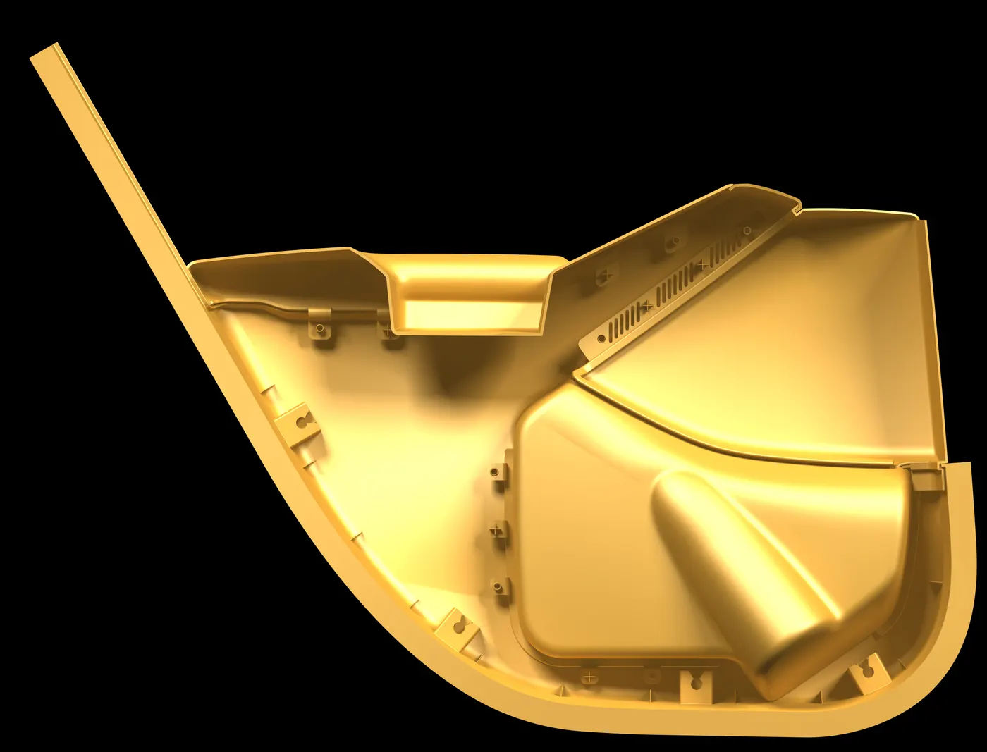
Week 12- Final project
DOOR_TRIM_SEPERATED_MODEL_WORKBENCH
Objectives: To create DOOR TRIM SEPERATED MODEL COMPONENT model using the Class-A Surface. It’s a plastic component so by keeping in mind all engineering constraints the model will be designed. HEAT STAKES and LOCATORS are the B-side features so by considering all the plastic defects norms the parts is going to be created. This starts with the TOOLING AXIS creation form the Class-A surface.

Introduction:
Class-A Surface: It is an outermost surface which is developed by the designers and it is provided as an input to the modeller to work on it.
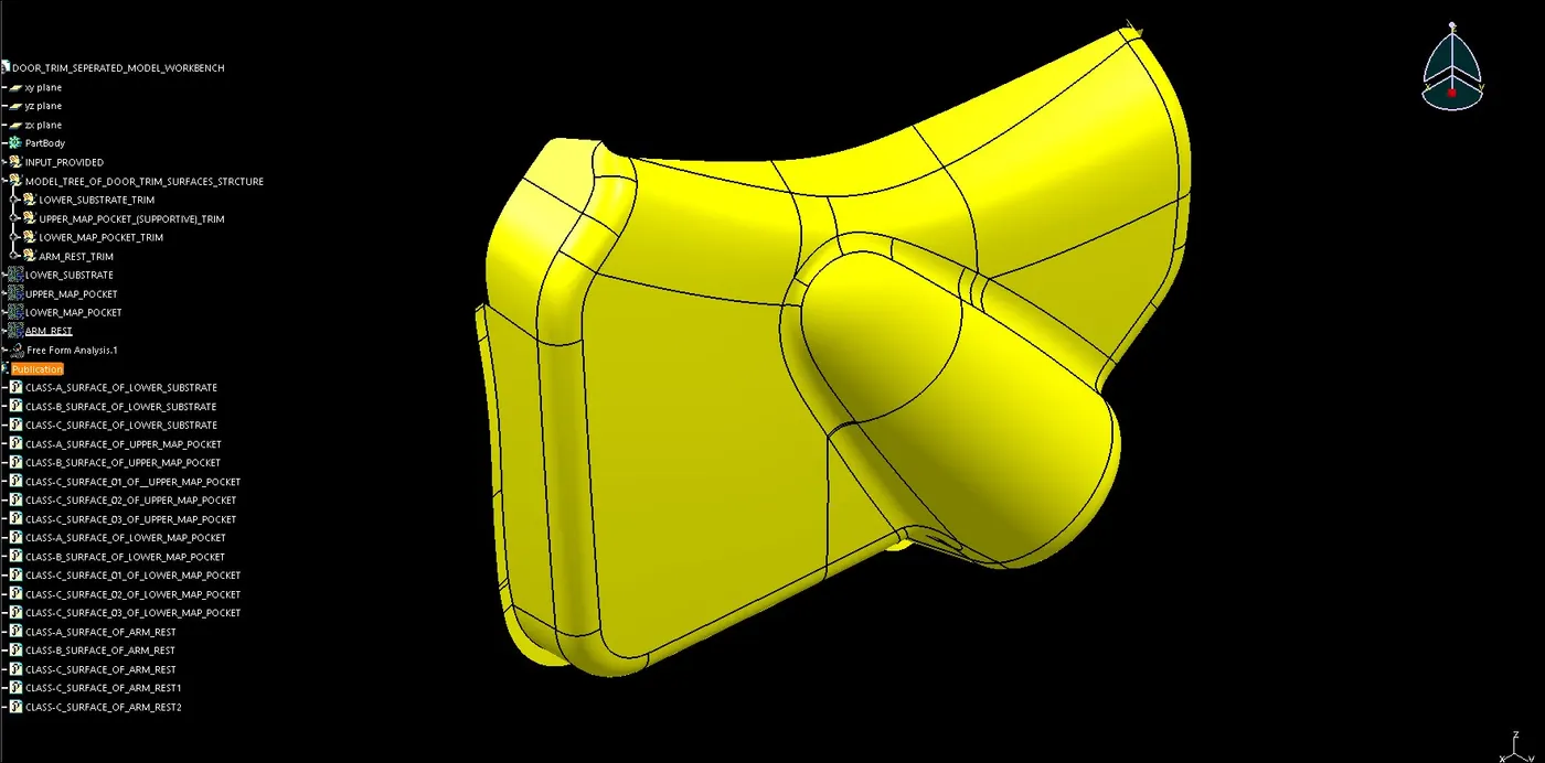
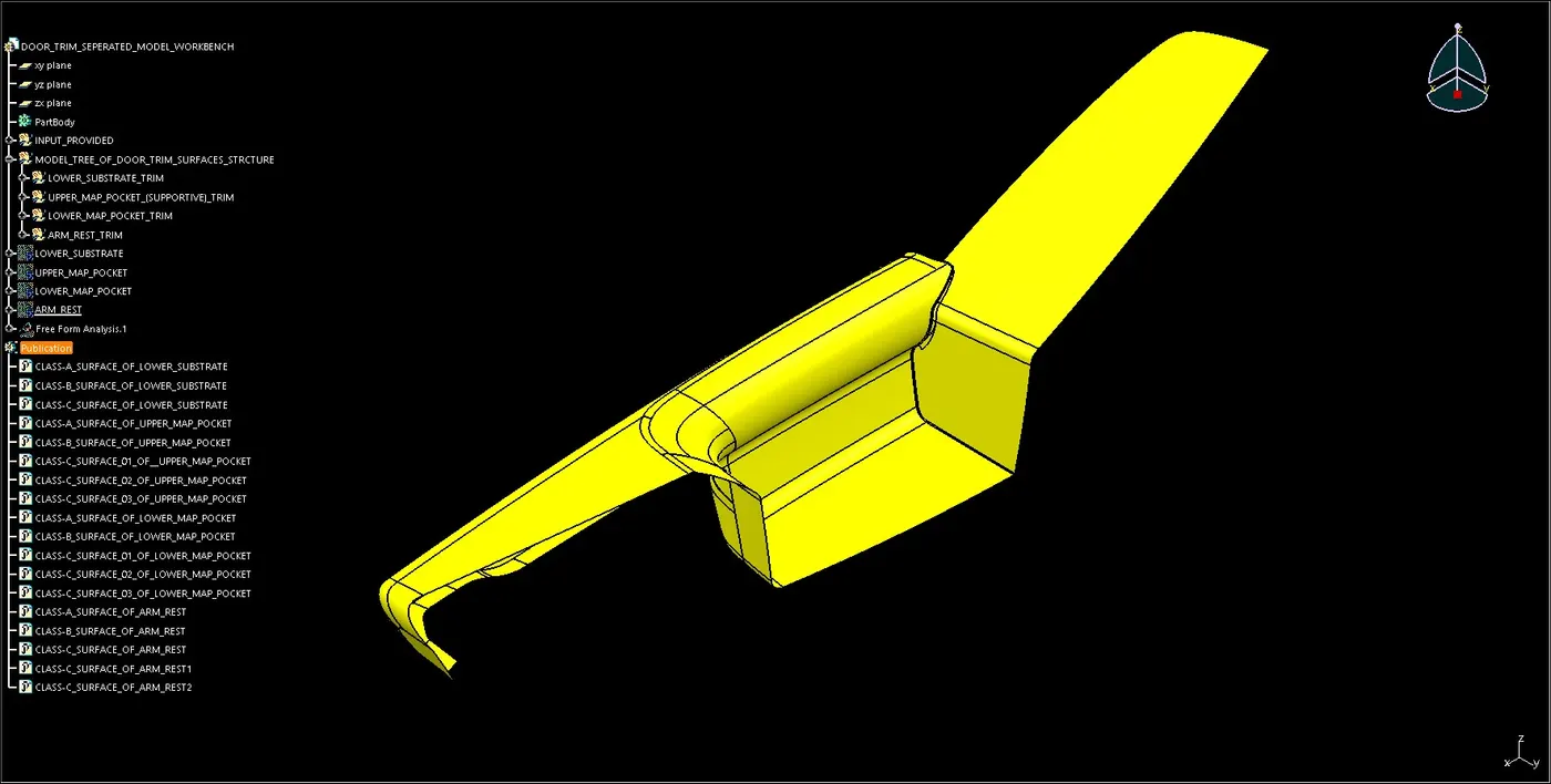
Class-B Surface: It is a surface at a certain thickness from the Class-A Surface.
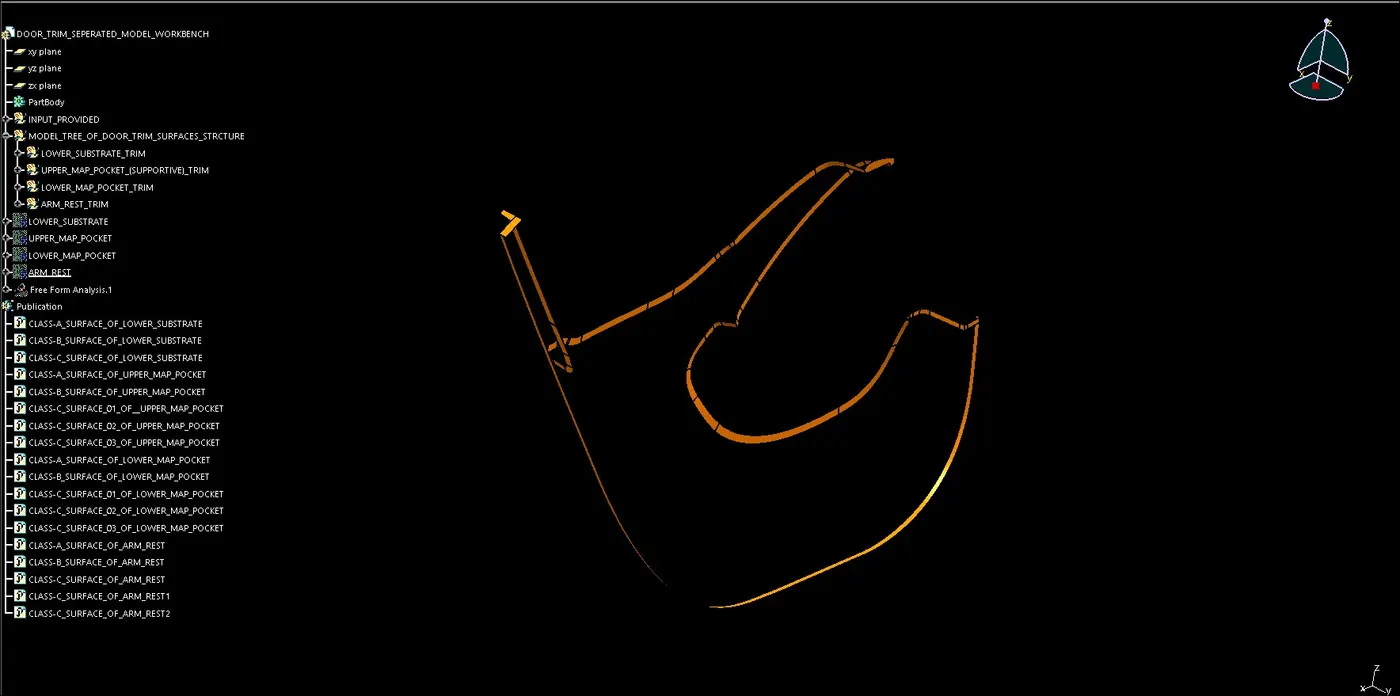
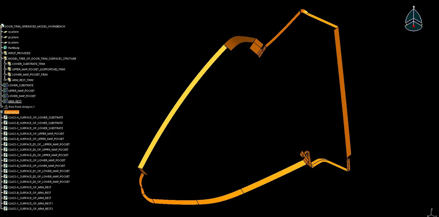
Class-C Surface: It is a surface that joins the Class-A and Class-B Surfaces.
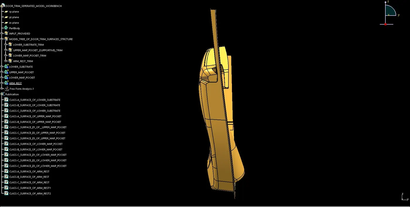
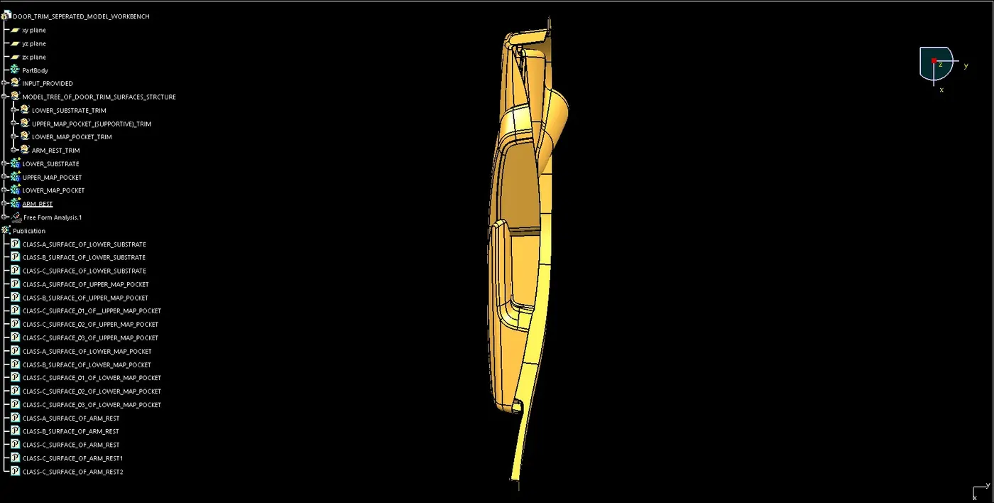
FOR TOOLING AXIS CREATION:
- First with the extract command one surface is extracted from Class-A surface.
- Now with the point command center is created on the extracted surface for creating a dummy tooling axis.
- Now creating a dummy tooling line along Y-axis direction with the line command.
- Finally TOOLING AXIS line created with the line command is created.
FOR SIDE CORE TOOLING AXIS CREATION:
- Using the same point as a center for creating a side core tooling axis.
- Now creating a tooling line along X-axis direction with the line command.
- Finally SIDE CORE TOOLING AXIS line is created.
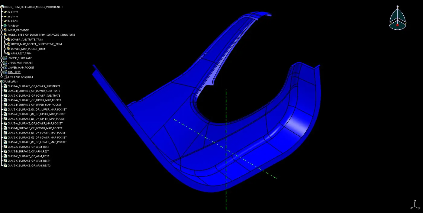
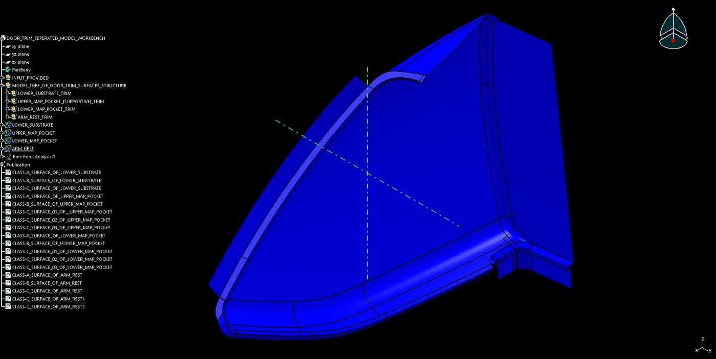
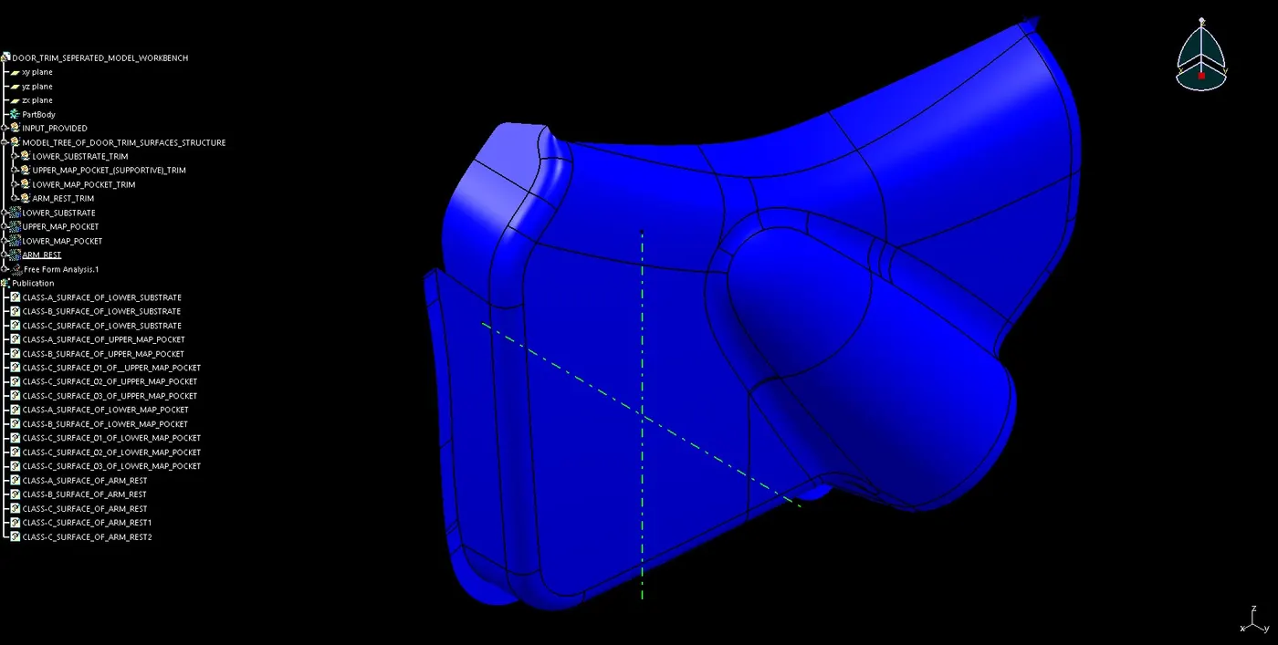
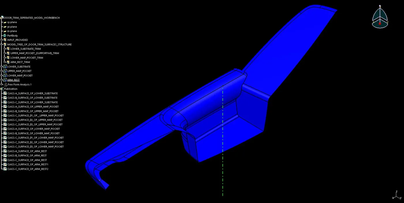
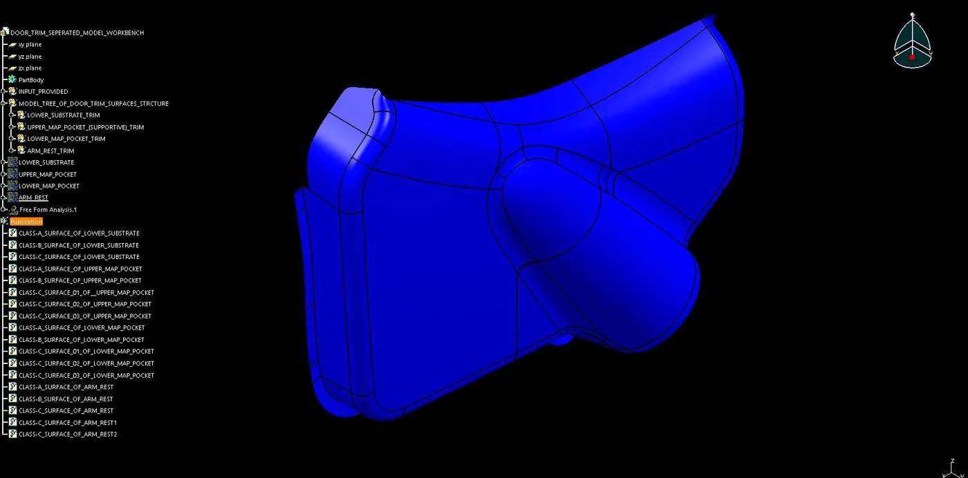
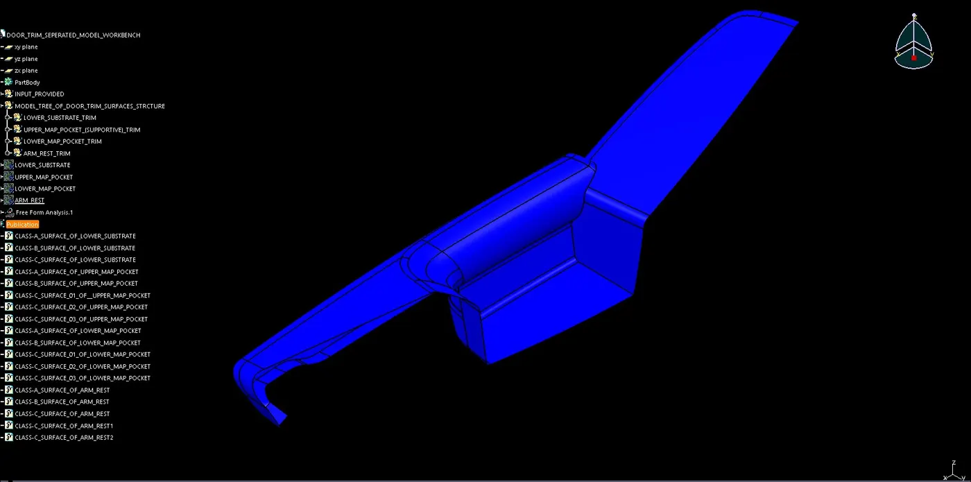
CLASS-A SURFACE: DOOR TRIM SURFACE
First we have to verify the Class-A Surface and if find any defects. The first preference is to inform the person who has provided you the Class-A surface that it has some defects and then start changing it. Improve all the defects and patches convert it into perfect surface.
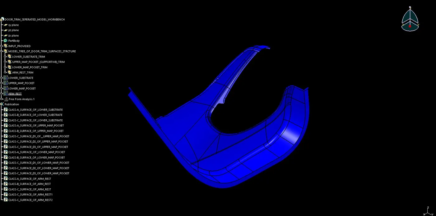
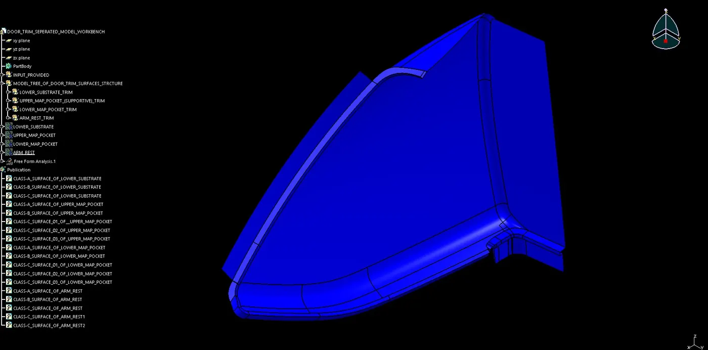
FOR CLASS-B SURFACE CREATION:
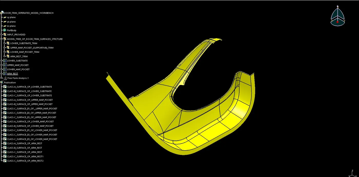
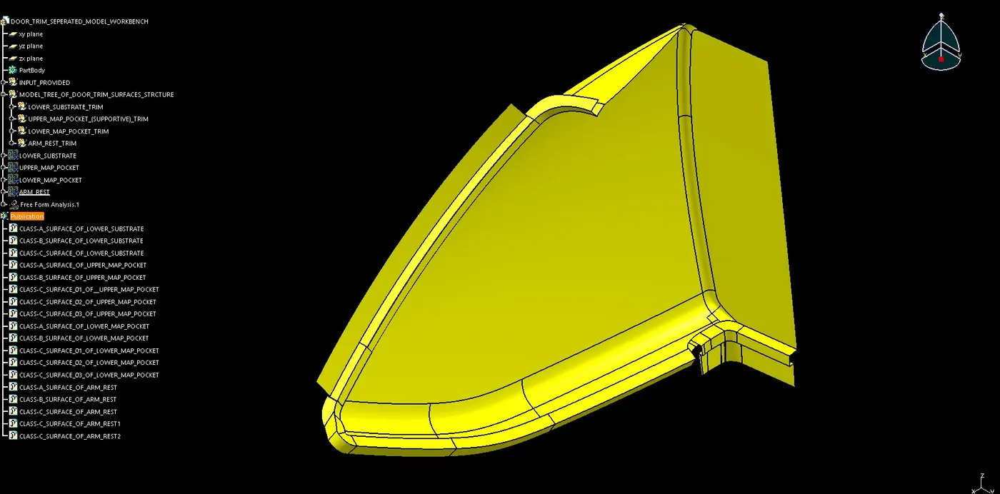
First we have to verify the Class-A Surface, that it should not have any defects of gaps or tangency error. So by directly offsetting the Class-A surface for creating Class-B surface which is of 2.5mm in distance. The previous methods can’t use cause for simple components the methods are easy to create any component but complex component like bumper, door trims, A-Pillar etc. which mainly deals with the surface commands, which is not easy to create those methods are not applicable. After the offset of Class-A surface, it can be seen that on Class-B surface some of the patches are missing. So for that all the missing patches should be filled below are the processes for filling the patches.
- First with the multiple extract command created the boundary lines around the gaps.
- Now with sweep command created a required surface.
- With join command filled patch is joined with the offset surface.
- Finally the Class-B Surface is created.
FOR CLASS-C SURFACE CREATION:
- It is seen that Door Trim surface is perpendicular to the tooling axis, so with the sweep command the extended surface is going to create.
- First by using boundary command creating a path for sweep.
- Now creating an extended surface with the sweep command by using ‘with draft direction’ and ‘with reference surface’.
- If it is not created in a single loop then use separated loops.
- Finally by using join or trim command create the Class-C Surface.
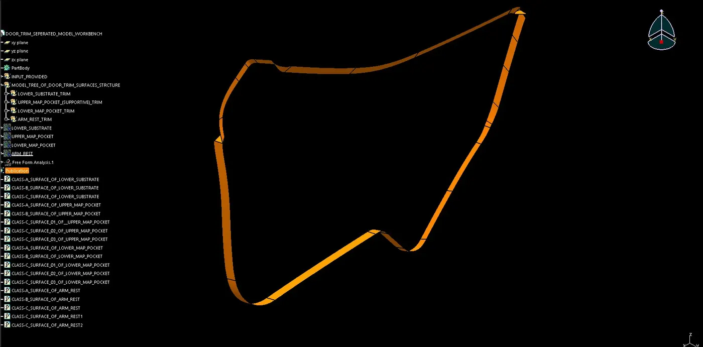
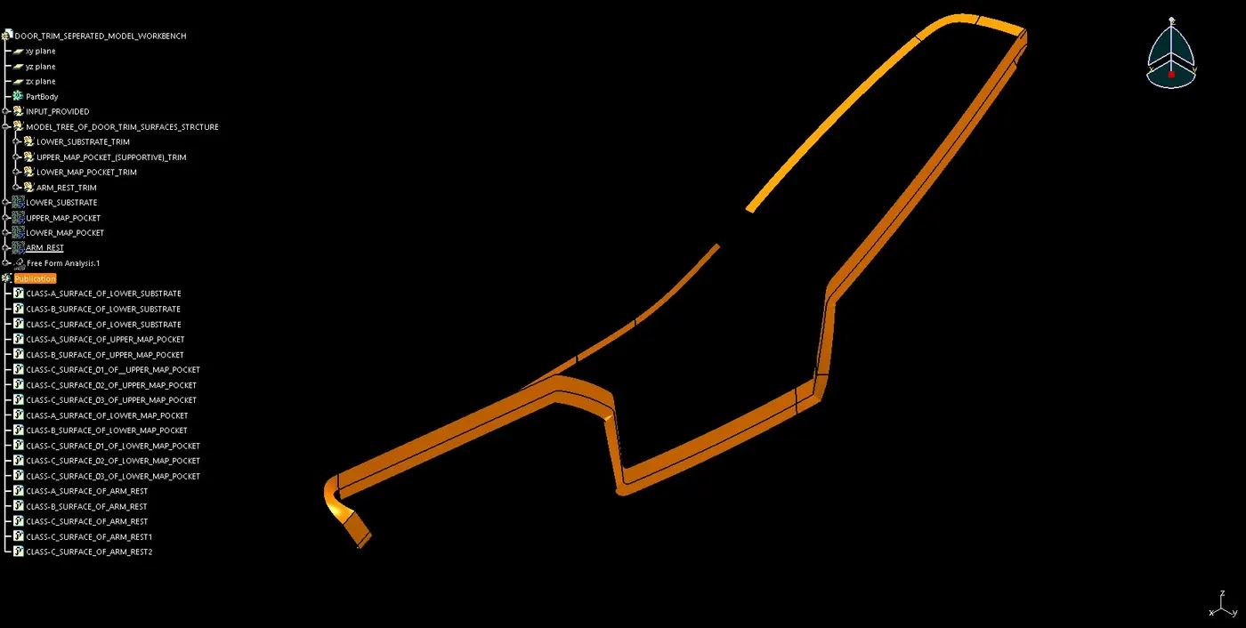
FINAL DOOR TRIM SURFACE CREATION:
- Now with join command, join the Class-A and Class-C surfaces.
- If it is seen that the Class-A and Class-C surfaces are not joining, then extrapolate both the surfaces and trim it.
- After trimming of Class-A & Class-C surfaces trim the achieved surface with the Class-B surface.
- Finally the closed surface body of the component is achieved in the surface design.
- Now move to part design with the close surface command, solidifying the component.
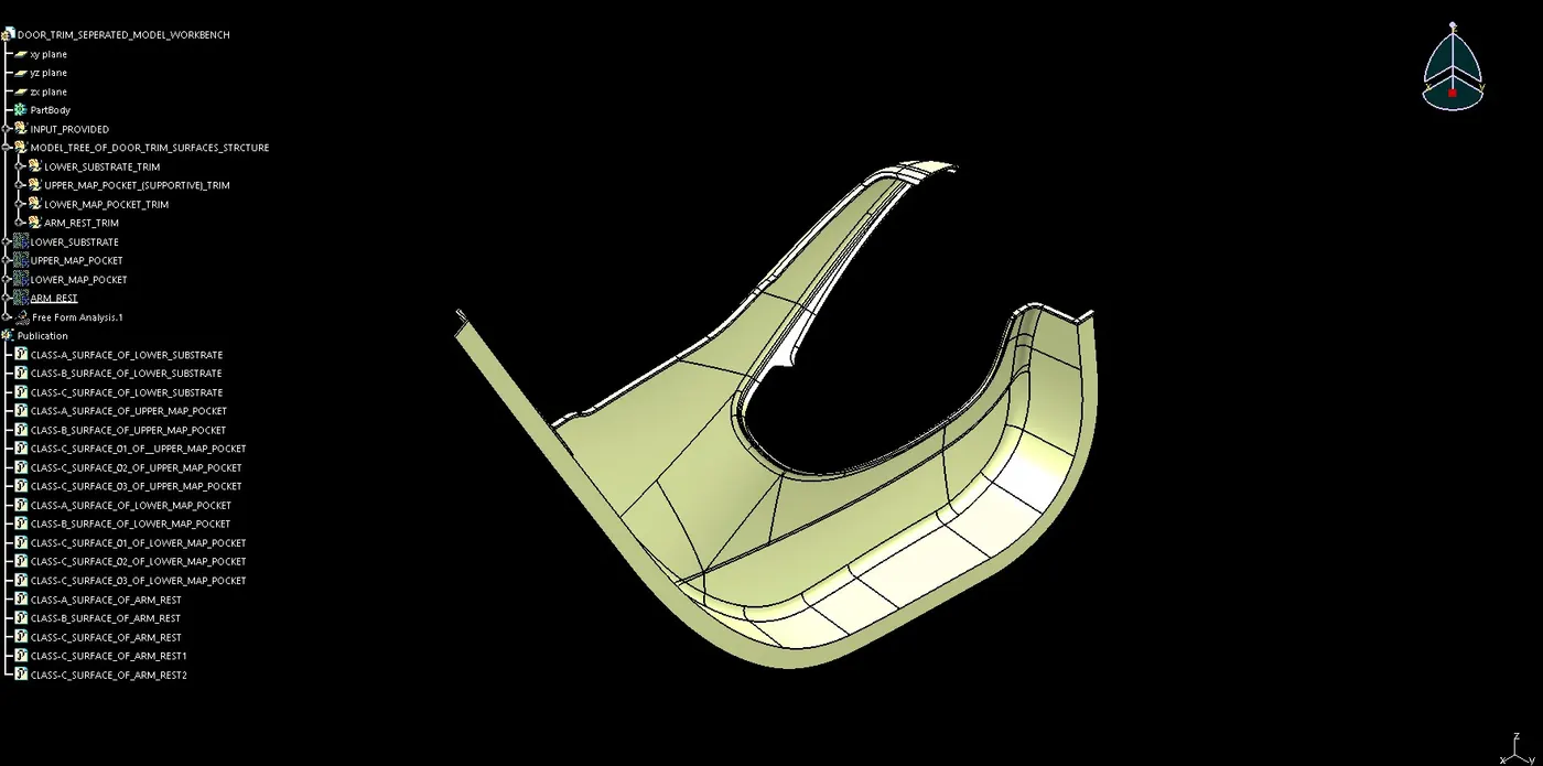
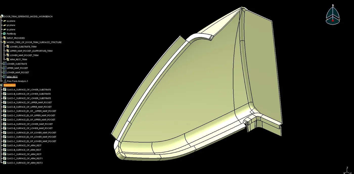
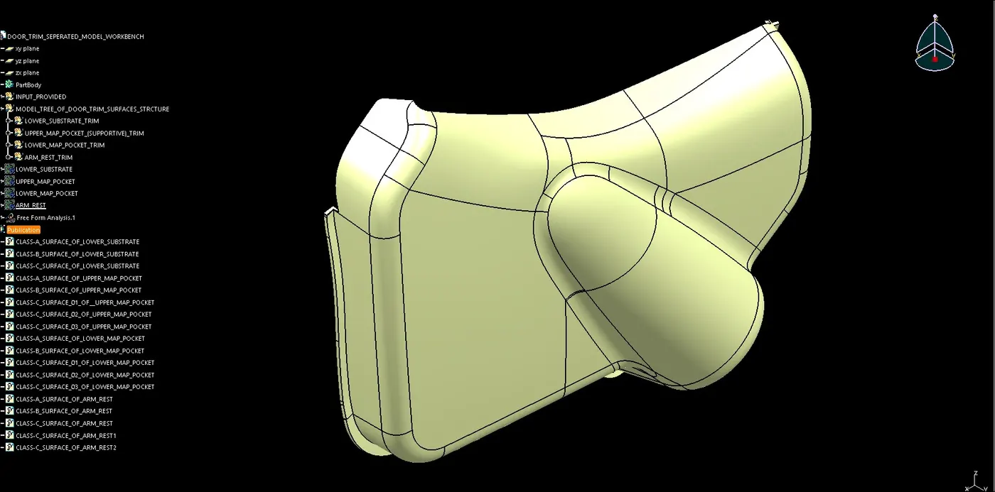
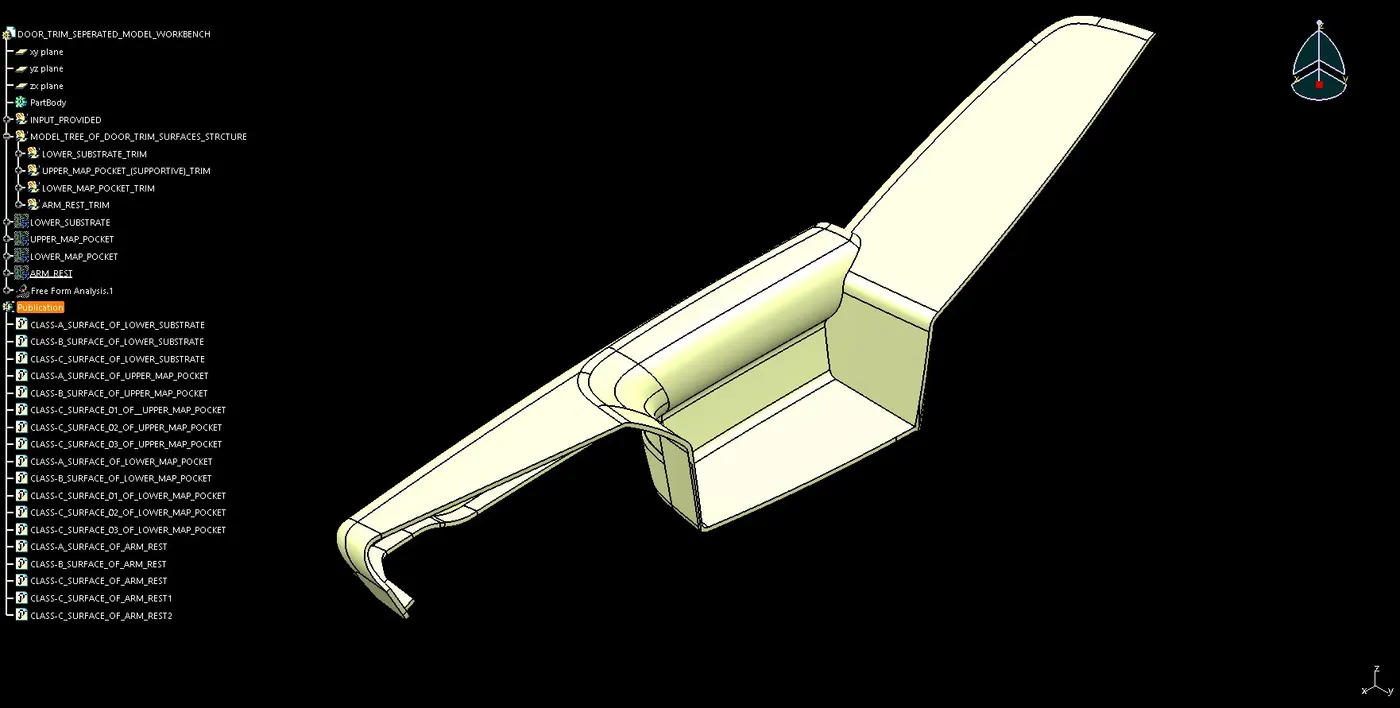
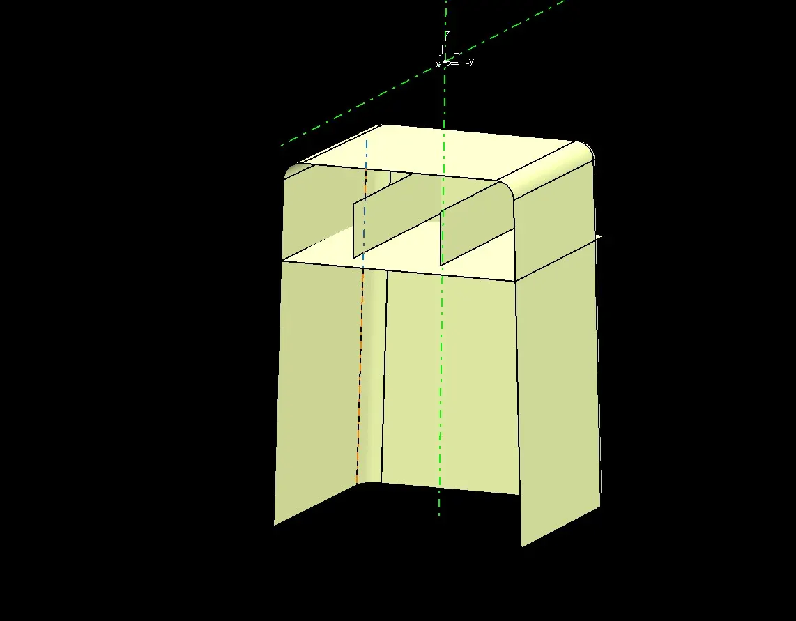
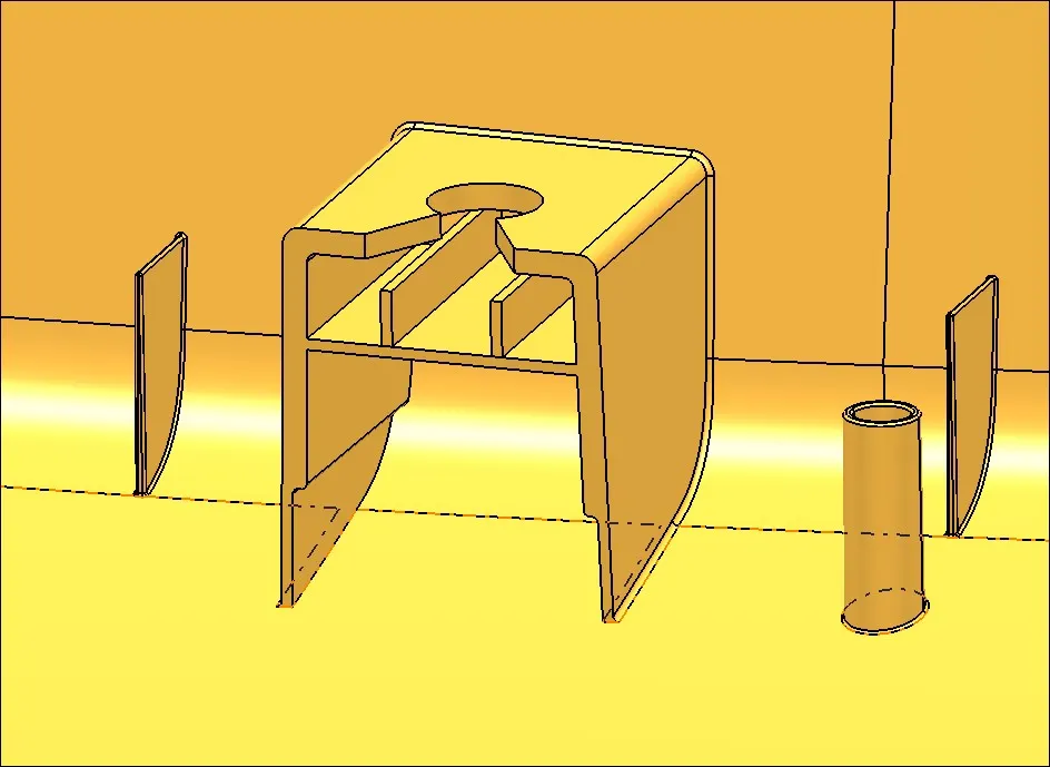
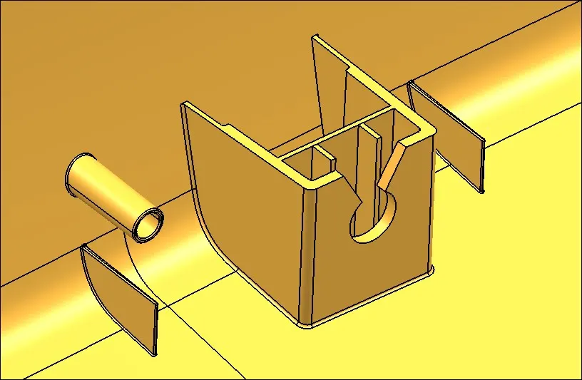
DOG HOUSE CREATION:
- First side core tooling axis is created for dog house creation.
- Now creating a point.
- Created a plane by referring the point.
- By using positioned sketch created the boundary line of dog house.
- Now by using sweep command created the outer wall of dog house and then covered the top.
- Now thickened the achieved surface with the thick-surface command.
- Now to achieve C thickness, we extract the surface and the offset it up to 6mm distance. Extracted the dog house inner surface and offset it to half of the thickness, trim both the achieve surfaces and finally achieved a required surface.
- Now in part design by using the split command we cut off the unwanted surface and provide draft in the inner surface.
- Now providing fillets on the edges as required.
- Finally the dog house is created.
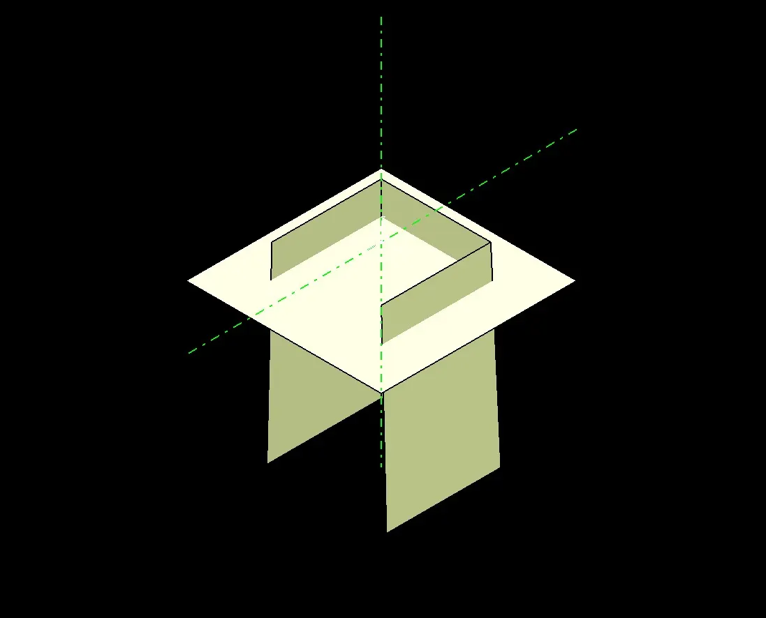
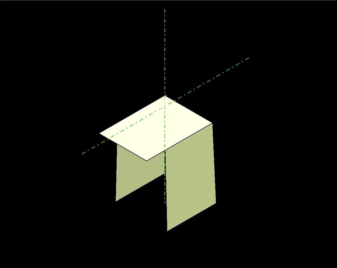
4 WAY LOCATOR CREATION:
- First with the point command creating the points and providing the positions where required.
- Now creating a plane and creating a sketch of 4 way locator.
- Now extruding the sketch up to 20mm distance and keeping the thickness 1.25mm with neutral fiber.
- Providing draft on all the sides of locator.
- Trim the locator with the solid body of Door Trim.
- Provide edge fillet on the sharp edges.
HEAT STAKE CREATION:
- First with the point command creating the points and providing the positions where required.
- Now creating a plane and creating a sketch of Heat Stake.
- Now extruding the sketch up to 15mm distance.
- Providing draft on the outer wall of Heat Stake.
- Now copy the part and do “PASTE SPEACIAL”, after it by using transition command putting the copied Heat Stake on the required positions.
- After positioning the Heat Stakes trim it with Door Trim.
- Finally provide fillets on the edges.
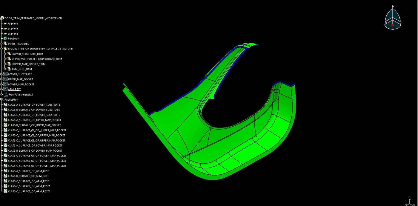
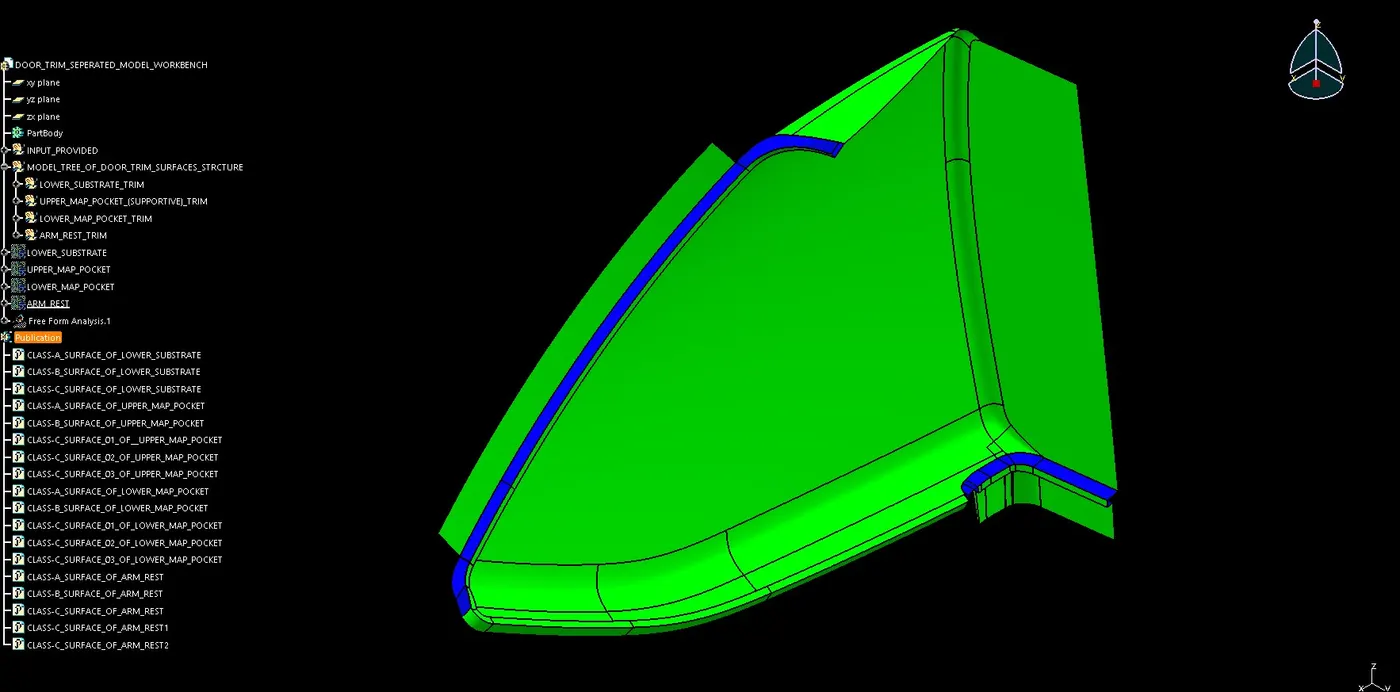
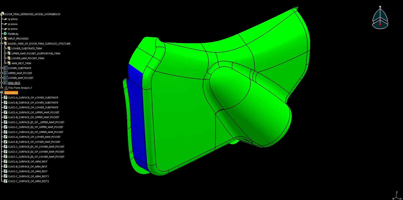
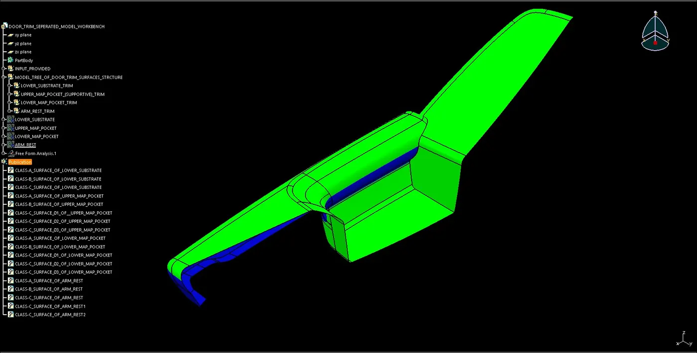
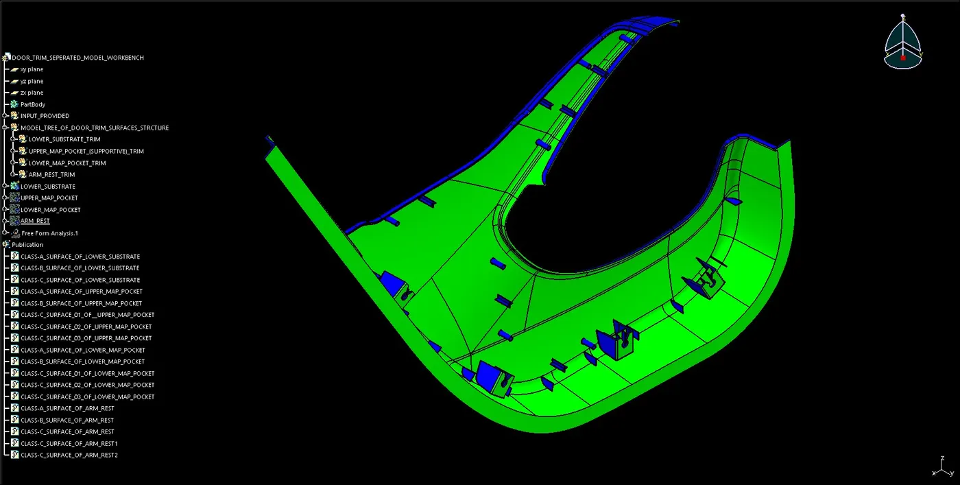
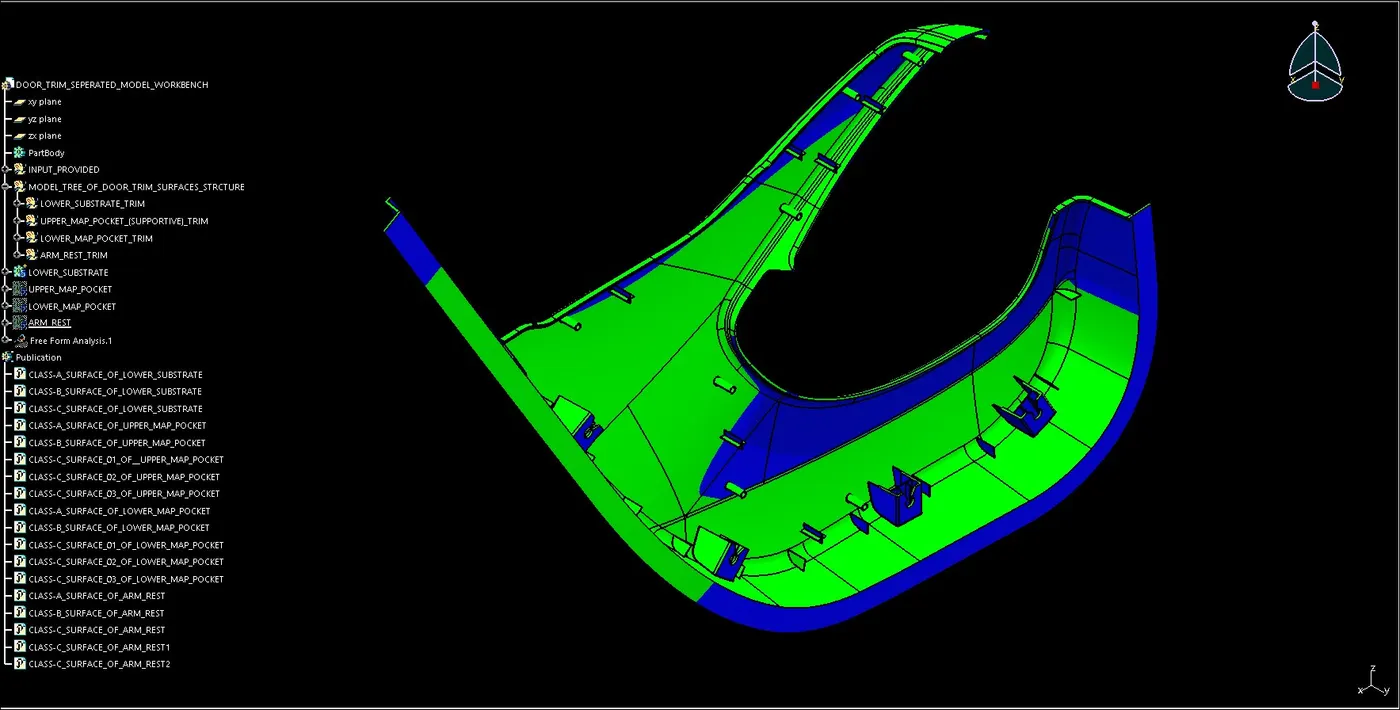
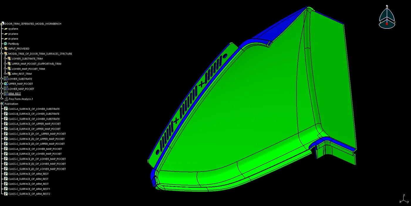
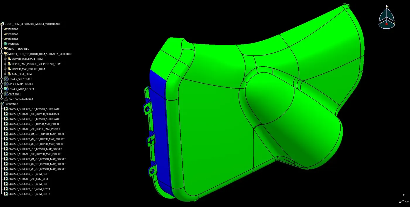
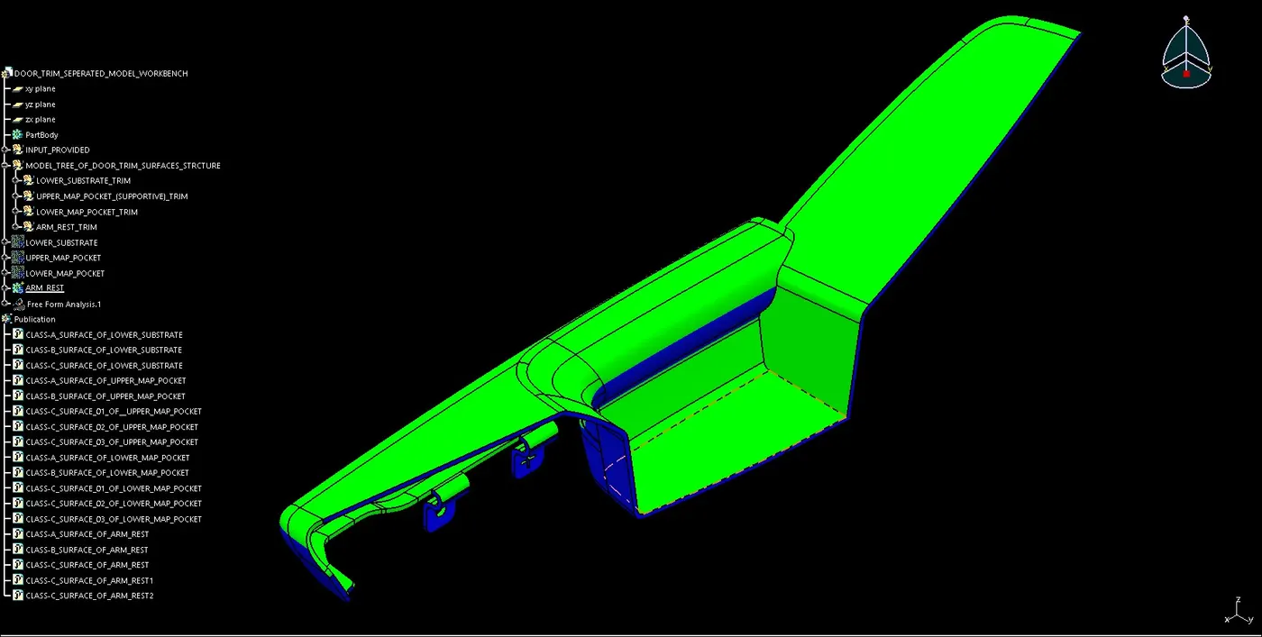
FOR DRAFT ANALYSIS CREATION:
- First set material mode, now click on the draft analysis.
- After opening an interface of draft analysis, click on the symbol of datum/compass align it with the tooling axis.
- Click on the surface and see that the surface is within the permissible limit of the draft values.
- Be ensuring that the surface should be green and if not flip the direction of the datum/compass it will turn into green.
- And after flipping the direction still not the draft analysis is not working, close the command and delete the 'Free From Analysis' and perform the process, it will start working.
- And if found that some area is still not turning into green, check the geometrical set or set the tooling axis with different values.
DRAFT ANALYSIS OF CLASS-A SURFACES:
DRAFT ANALYSIS OF SOLID BODY OF DOOR TRIMS:
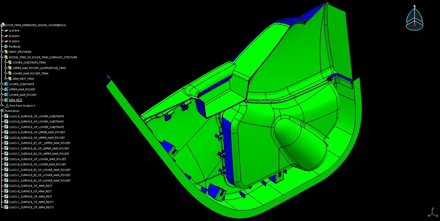
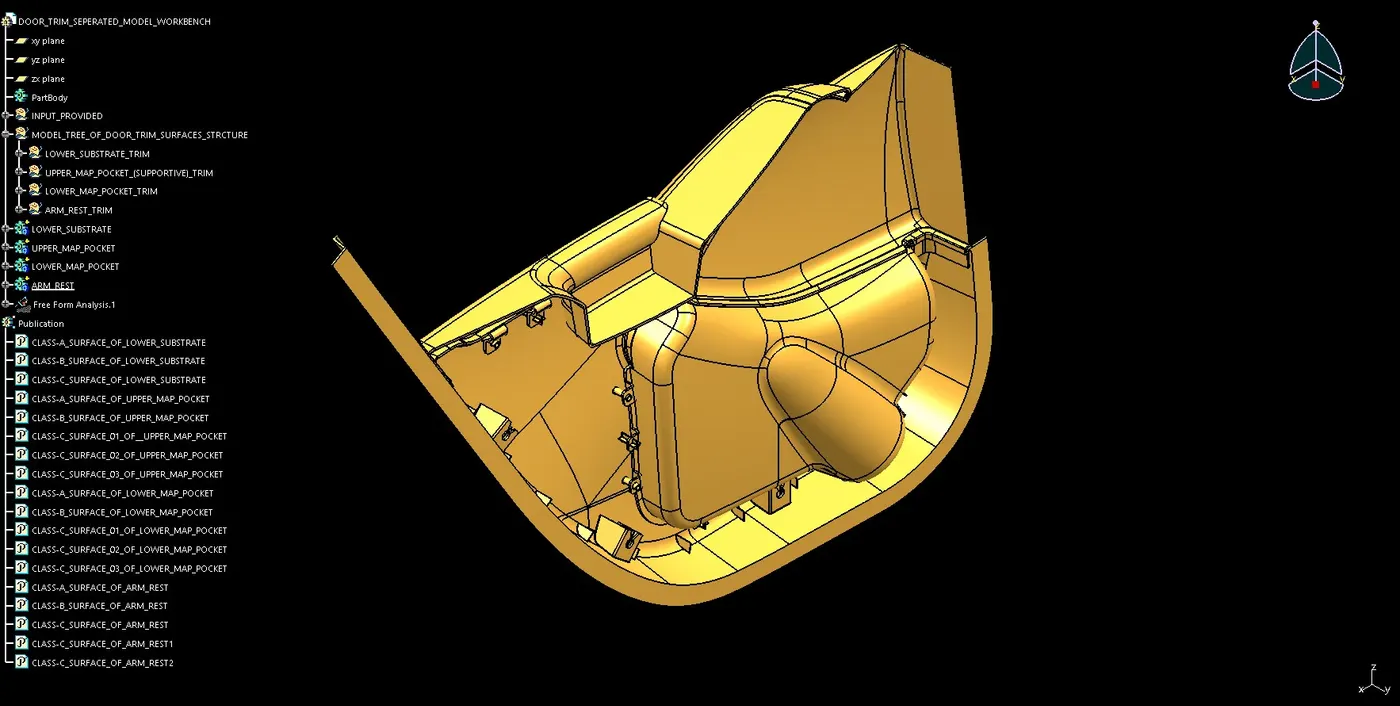
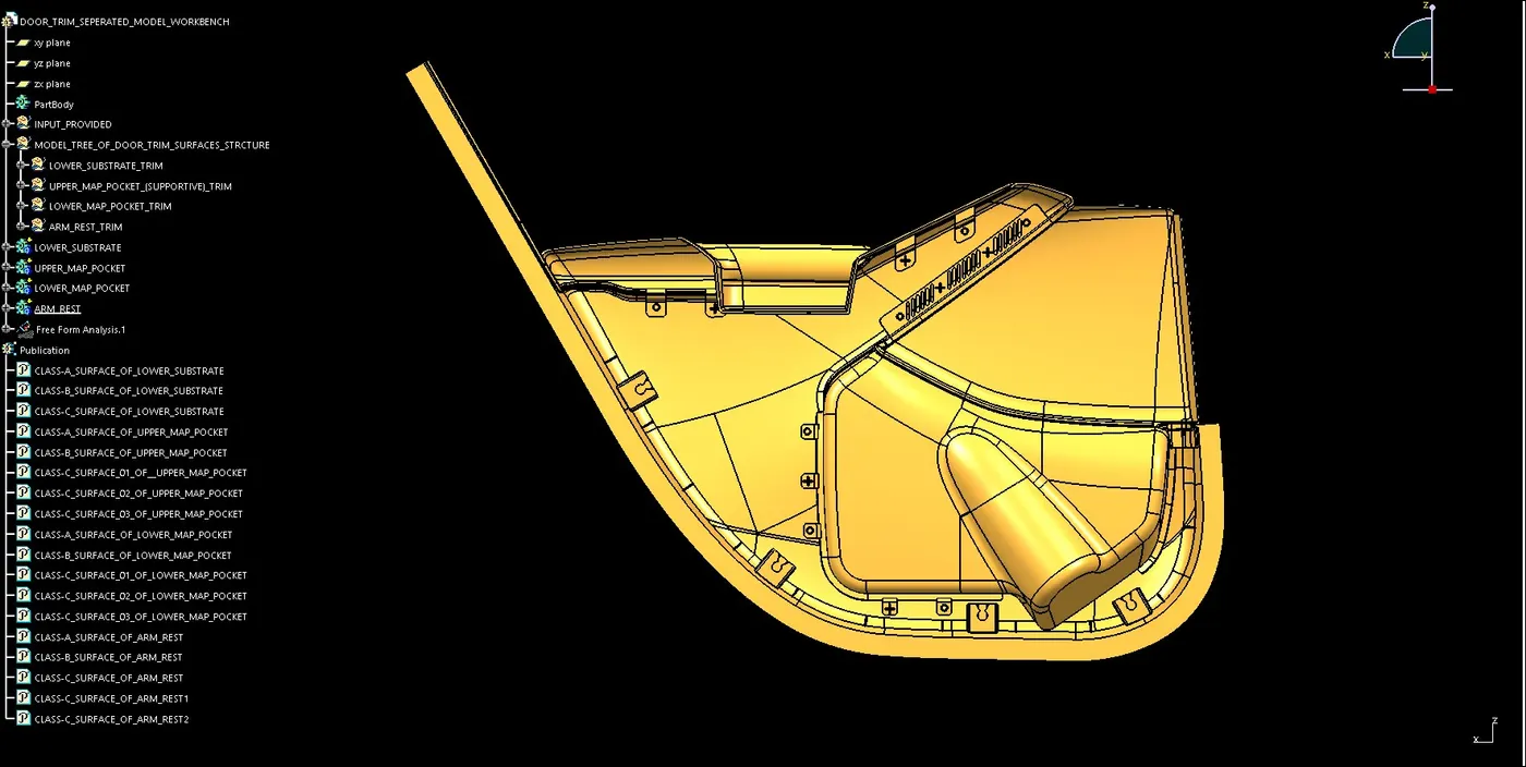
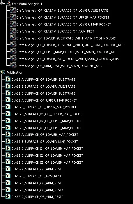
MODEL TREE STRUCTURE AND MODIFYING FEATURES OF DOOR TRIMS:
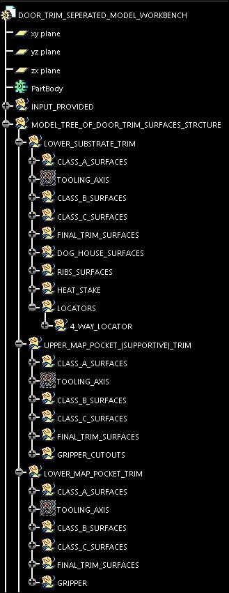
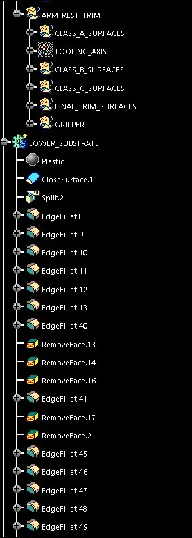
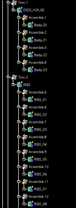
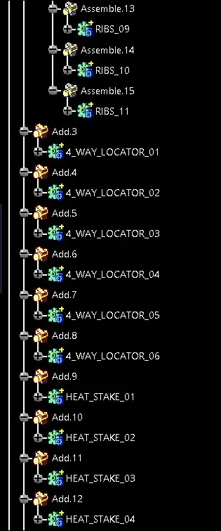
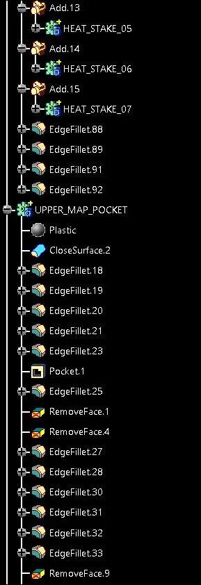
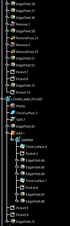
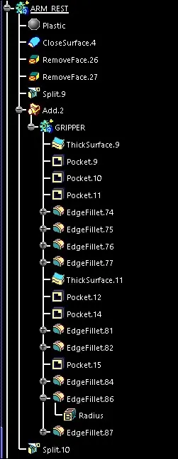
DOOR TRIMS WITH PLASTIC MATERIAL:
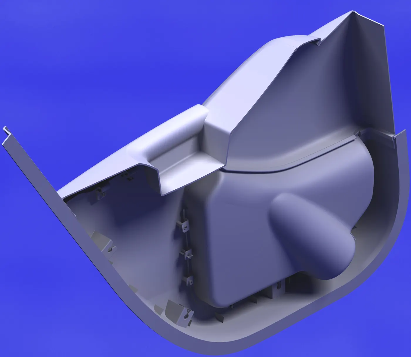
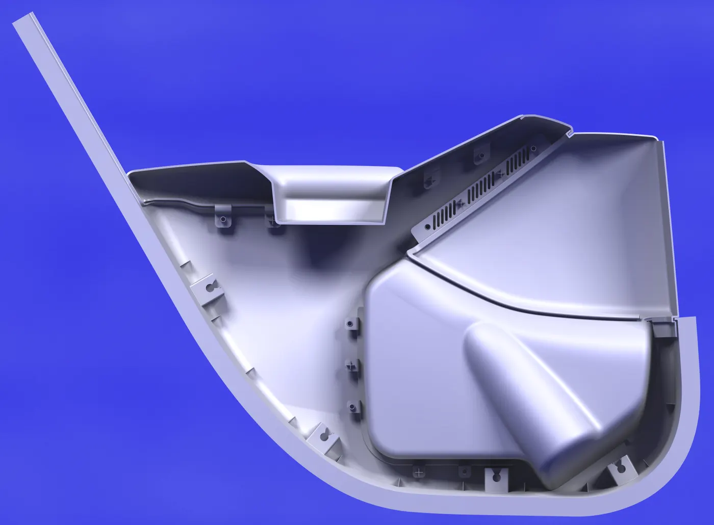
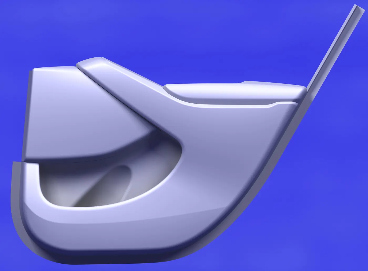
DOOR TRIMS WITH COLOUR TEXTURE: