Week 10 - Challenge 1- Attachment Feature Creation (Ribs & Screw Boss)
DOOR HANDLE WORKBENCH
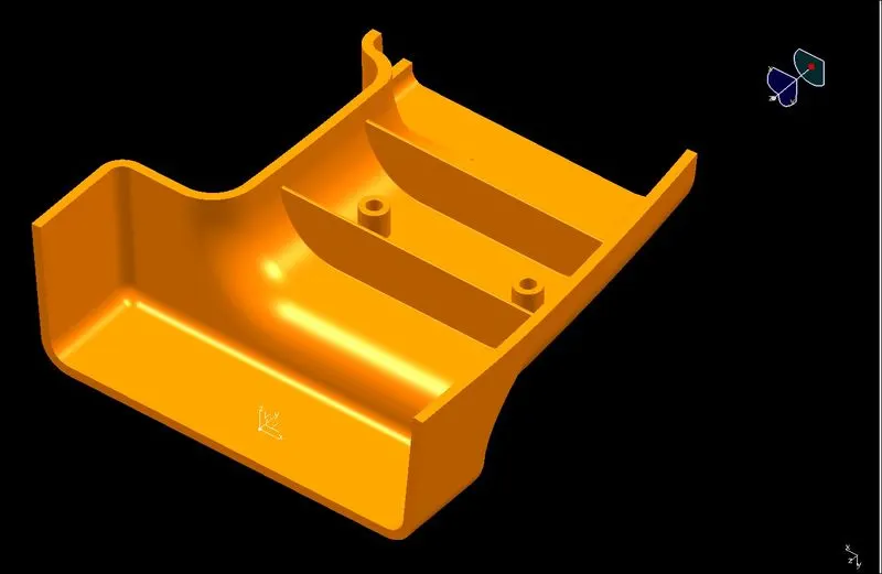
Objectives: To create DOOR HANDLE (RIBS & SCREW BOSS) COMPONENT model using the Class-A Surface. It’s a plastic component so by keeping in mind all engineering constraints the model will be designed. This starts with the TOOLING AXIS for the Class-A surface should be created.
Introduction:
Class-A Surface: It is an outermost surface which is developed by the designers and it is provided as an input to the modeller to work on it.
Class-B Surface: It is a surface at a certain thickness from the Class-A Surface.
Class-C Surface: It is a surface that joins the Class-A and Class-B Surfaces.
Orientation views: Front, Side, Top and Isometric
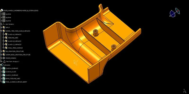
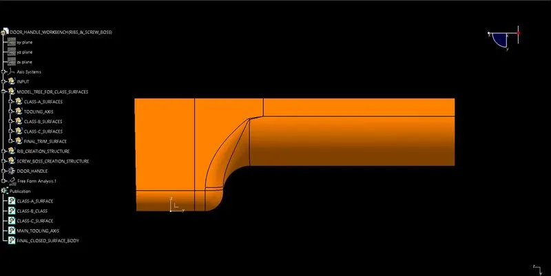
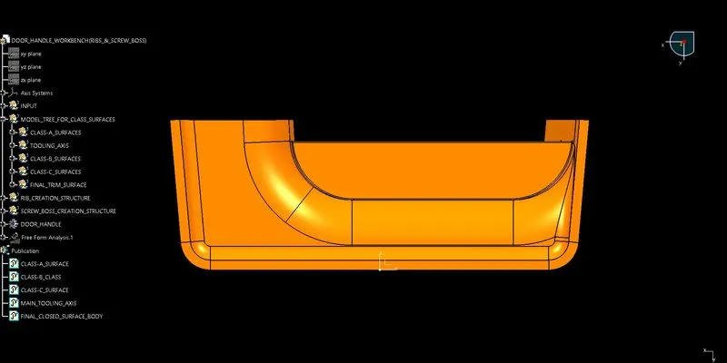

Commands or tools were used to create a closed surface/solid model, performing on the Class-A surface:
OFFSET >> BOUNDARY >> TRIM >> EDGE FILLET >> SWEEP >> JOIN >> CLOSED SURFACE (Part Design) >> DRAFT ANALYSIS
FOR TOOLING AXIS CREATION:
- First with axis system created on Class-A surface for creating a dummy tooling axis.
- Now creating a point using point command.
- Now creating a dummy tooling axis with the line command.
- Now using the intersect command, we achieved a boundary line at a Class-A surface.
- Creating a line on the achieved boundary line with the line command.
- Finally creating TOOLING AXIS line with the line command using bisecting.
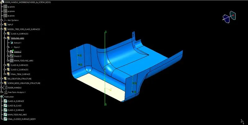
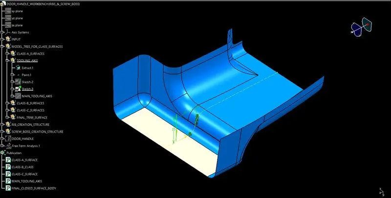
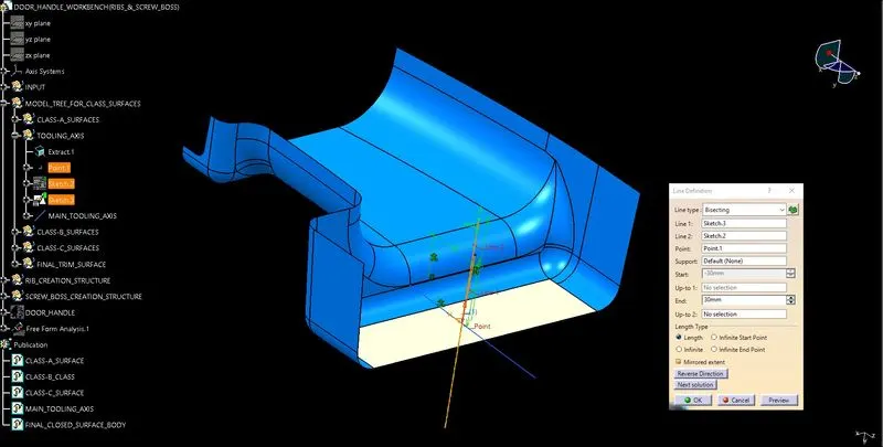
FOR CLASS-B SURFACE CREATION:
First we directly offset the Class-A surface for creating Class-B surface which is of 2.1mm in distance. The previous methods can’t use cause for simple components the methods are easy to create any component but complex component which is not easy to create those methods are not applicable. After the offset of Class-A surface, it can be seen that on Class-B surface some of the patches are missing. So for that all the missing patches should be filled below are the processes for filling the patches.
SURFACE CREATION:
- In this section by using join command, removing those surfaces which are not required.
- Now with the boundary command line is created and extruded to get a surface output.
- Again with the same command created a second surface.
- Finally both the achieved surfaces are trimmed with the trim command to get the final output surface.
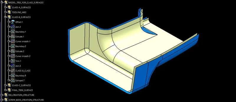
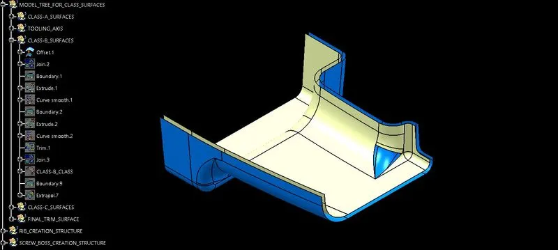
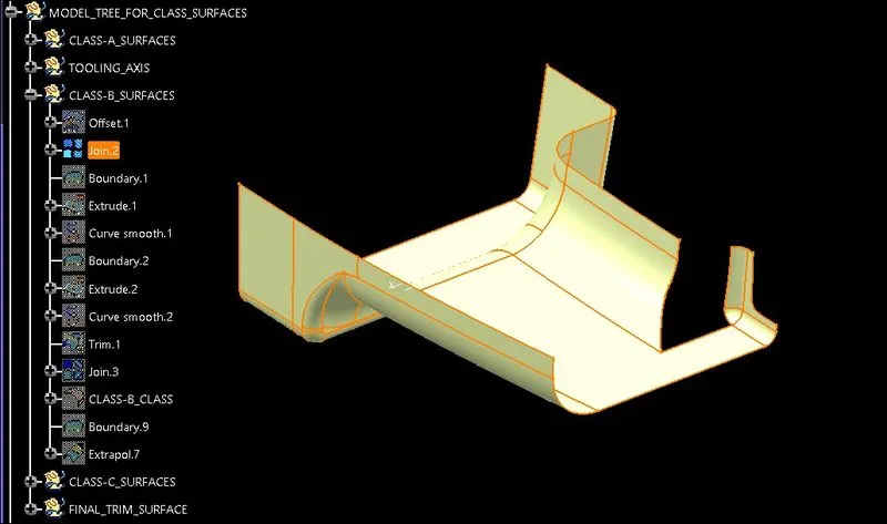
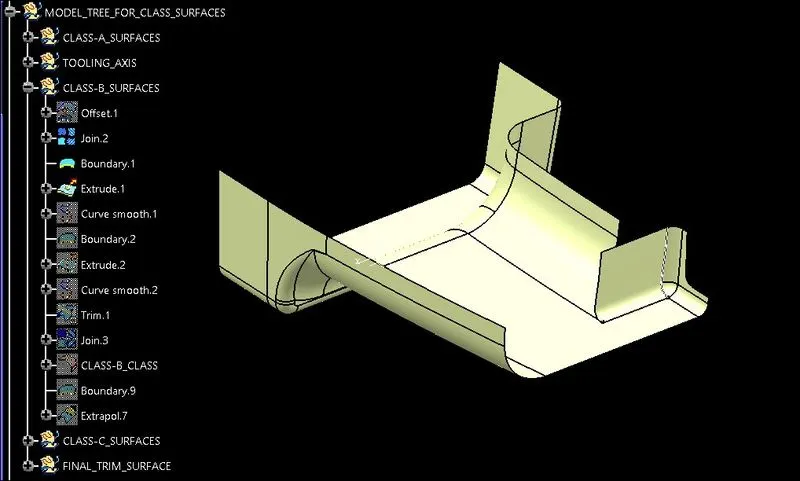
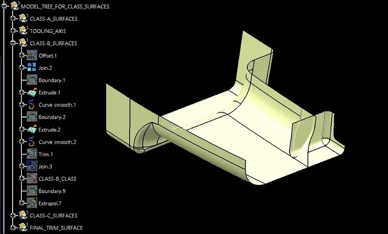
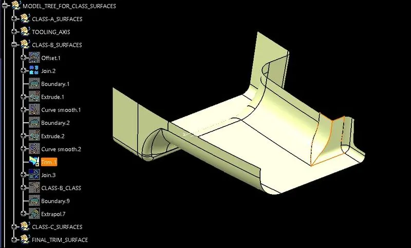
FINAL CLASS-B SURFACE CREATION:
- Finally by providing fillets on the achieved trimmed surface Class-B Surface is created.
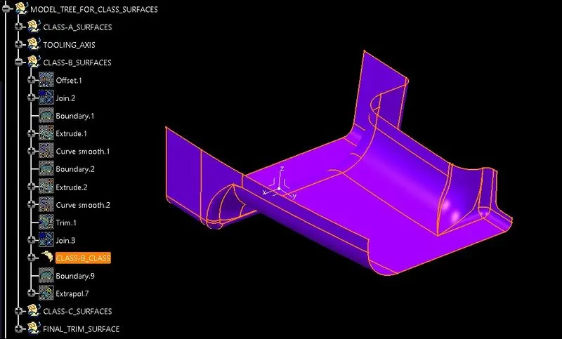
FOR CLASS-C SURFACE CREATION:
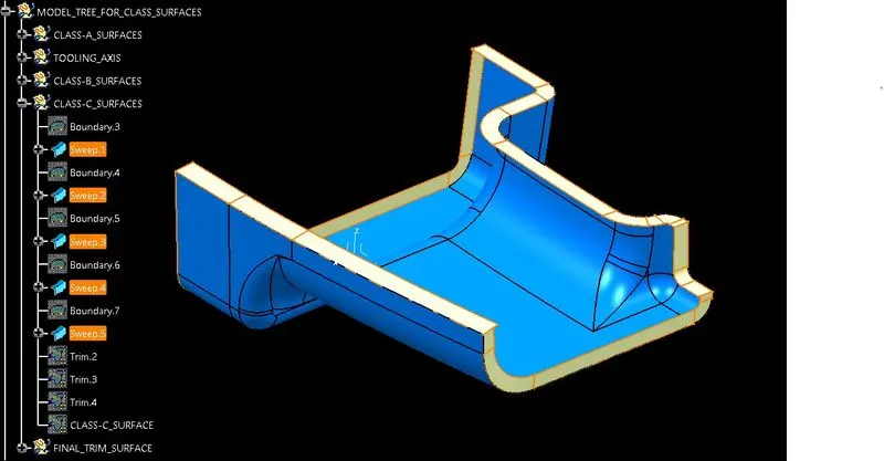
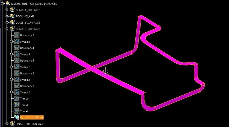
- It is seen that with respect to tooling axis outer boundary surface is parallel to it, so with the sweep command the extended surface is going to create.
- By using boundary command creating a path for sweep.
- Now creating an extended surface with the sweep command by using ‘with reference surface’.
FINAL DOOR HANDLE SURFACE CREATION:
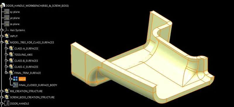
- Now with join command, join the Class-A and Class-C surfaces.
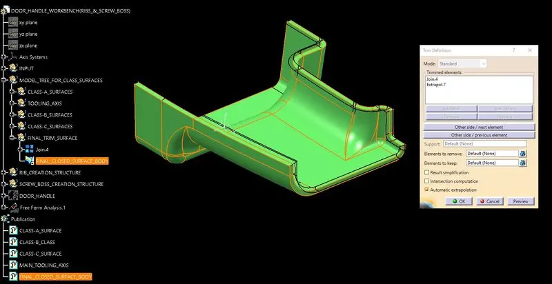
- After joining of Class-A & Class-C surfaces trim the achieved surface with the Class-B surface.
- Finally the closed surface body of the component is achieved in the surface design.
- Now move to part design with the close surface command, solidifying the component.
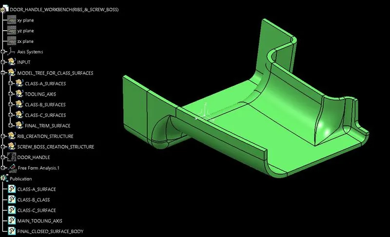
RIBS CREATION:
- First plane is created with plane command.
- Now with the sketch command rib boundary is sketched.
- With the fill command the sketch boundary is filled.
- Move to part design and thickened the surface with the thicken command.
- Now by using draft command drafting the rib.
- Finally providing the fillets.
- Repeat the same process for the second rib.
THICKNESS: 1MM (2.1x0.4=0.84MM)
HEIGHT: 12.5MM
FILLET: 0.25MM
DRAFT: 0.5MM
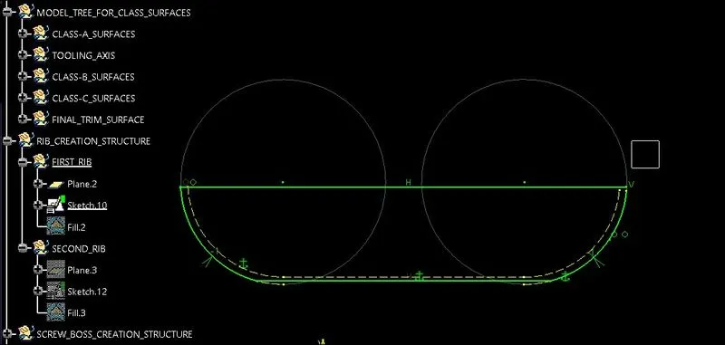
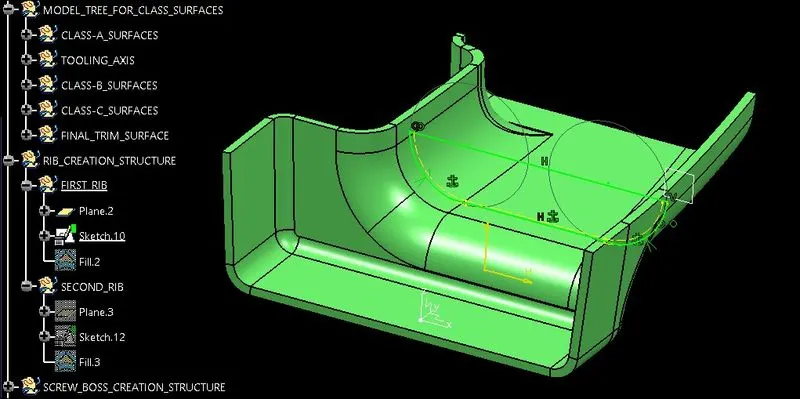
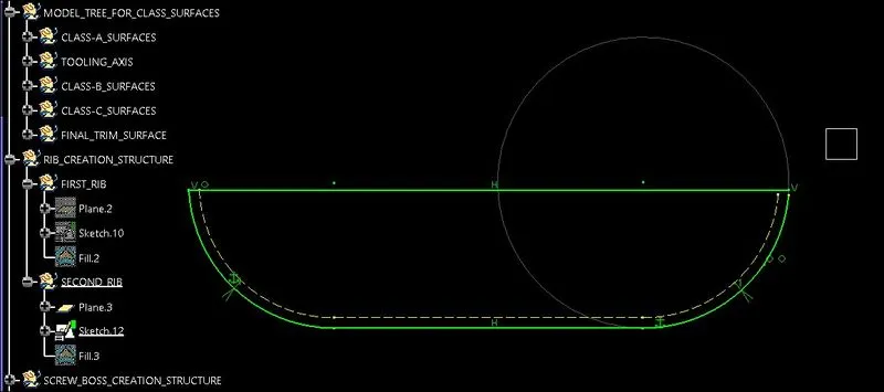
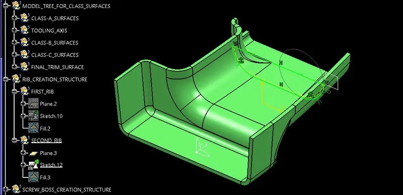
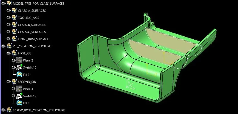
SCREW BOSS CREATION:
- First plane is created with plane command.
- Now with the sketch command screw boss holes diameters boundary is sketched.
- With the pad command the sketch is extruded.
- Now by using draft command drafting the screw boss.
- Finally providing the fillets.
- Repeat the same process for the second screw boss.
DIAMETER (M3 SCREW): OD-6MM, ID-3MM
HEIGHT: 6.3MM (T=3T)
FILLET: 0.25MM
DRAFT: 0.5MM
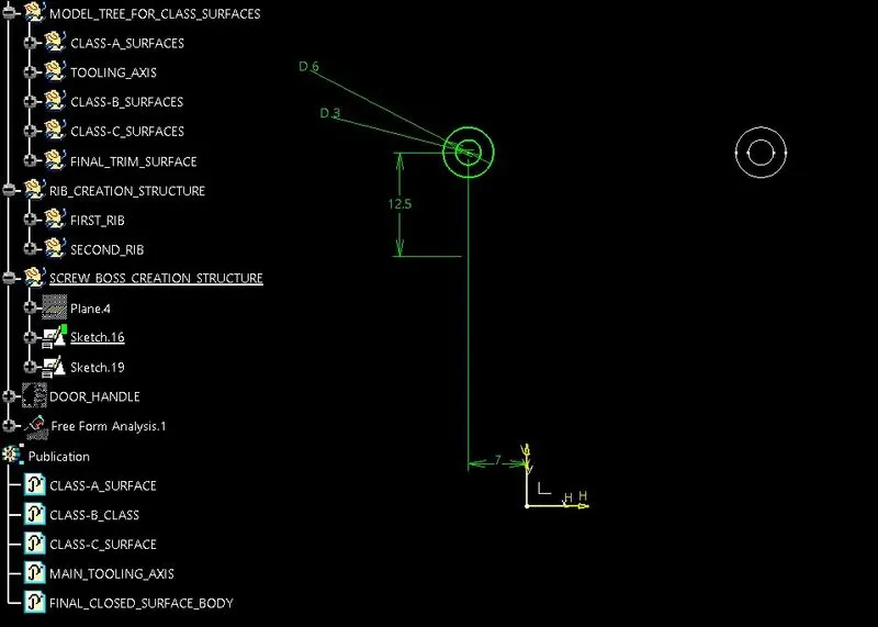
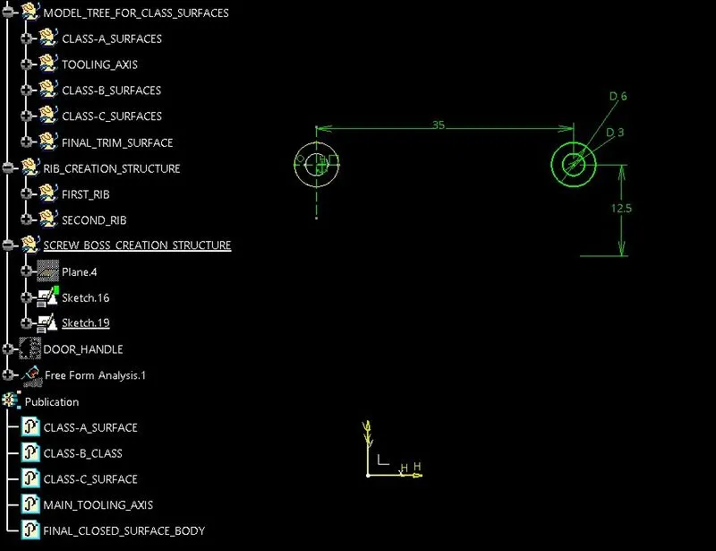
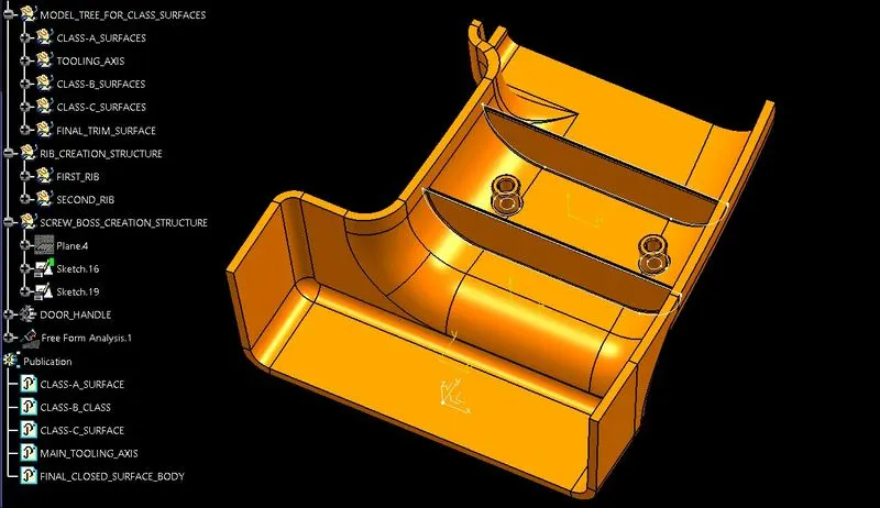
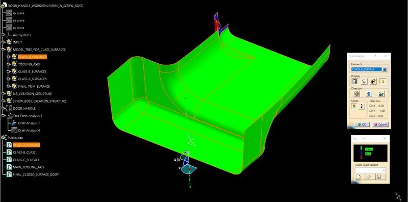
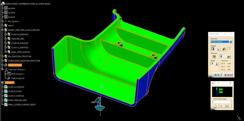
FOR DRAFT ANALYSIS CREATION:
- First set material mode, now click on the draft analysis.
- After opening an interface of draft analysis, click on the symbol of datum/compass align it with the tooling axis.
- Click on the surface and see that the surface is within the permissible limit of the draft values.
- Be ensuring that the surface should be green and if not flip the direction of the datum/compass it will turn into green.
- And after flipping the direction still not the draft analysis is not working, close the command and delete the 'Free From Analysis' and perform the process, it will start working.
- And if found that some area is still not turning into green, check the geometrical set or set the tooling axis with different values.