Week 9 - Challenge 2 - Switch Bezel Design
SWITCH BEZEL WORKBENCH
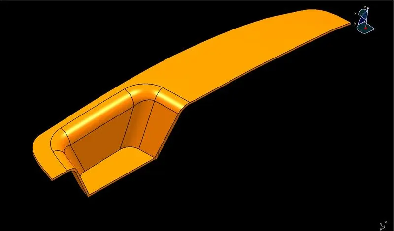
Objectives: To create SWITCH BEZEL COMPONENT model using the Class-A Surface. It’s a plastic component so by keeping in mind all engineering constraints the model will be designed. This starts with the TOOLING AXIS for the Class-A surface should be created.
Introduction:
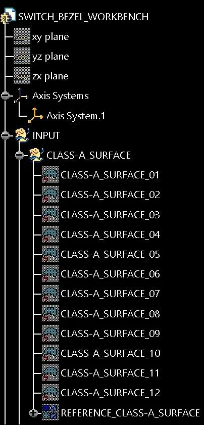
Class-A Surface: It is an outermost surface which is developed by the designers and it is provided as an input to the modeller to work on it.
Class-B Surface: It is a surface at a certain thickness from the Class-A Surface.
Class-C Surface: It is a surface that joins the Class-A and Class-B Surfaces.
Commands or tools were used to create a closed surface/solid model, performing on the Class-A surface:
INTERSECT >> EXTRACT >> UN-TRIM >> EXTRAPOLATE >> TRIM >> OFFSET >> EDGE FILLET >> BOUNDARY >> SWEEP >> JOIN >> CLOSED SURFACE (Part Design) >> DRAFT ANALYSIS
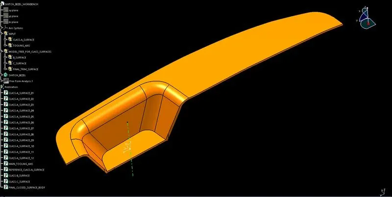
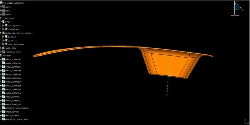
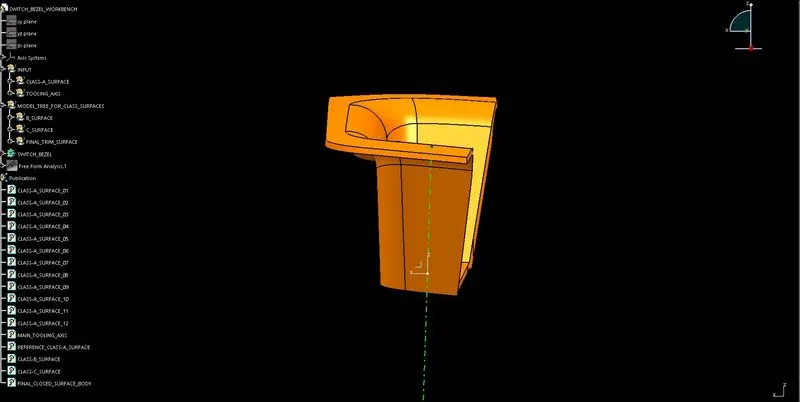
Orientation Views:- Front, side, top and isometric views.
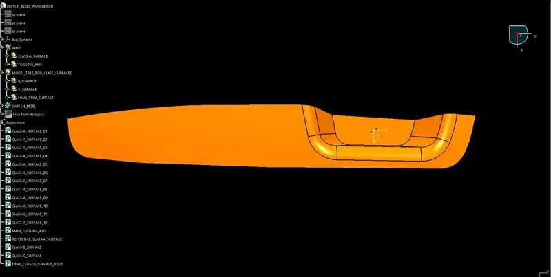
FOR TOOLING AXIS CREATION:
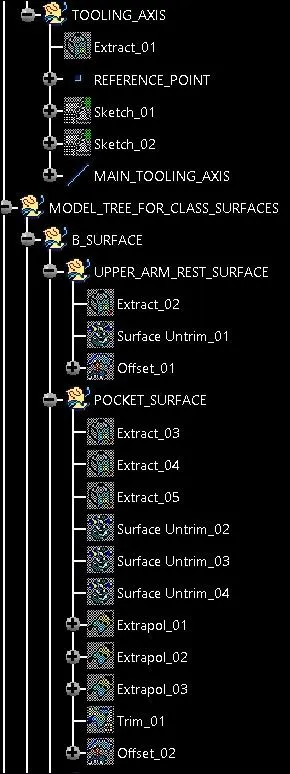
- First with the extract command base surface is created from Class-A after that creating a point using point command with the reference of base surface.
- Now creating a dummy tooling line along YZ plane with the position sketch by sketching two inclined lines and then bisecting those two lines.
- Now again with the same process creating second dummy tooling line along XZ plane.
- Finally creating TOOLING AXIS line with the line command using bisecting.
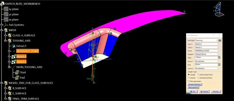
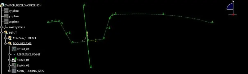
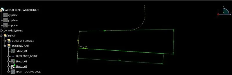
FOR CLASS-B SURFACE CREATION:
UPPER ARM REST SURFACES CREATION:
- First with the extract command the arm rest surface will be created from the Class-A surface.
- After extraction, Un-trim command is used to remove the sharp or curved edges and creating straight edges.
- As the thickness of the component is 2.5mm, so by using offset command the achieved desired shape is now Offset up to 2.5mm distance.
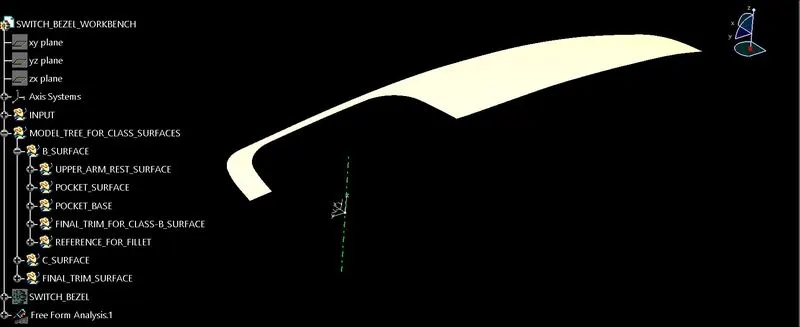
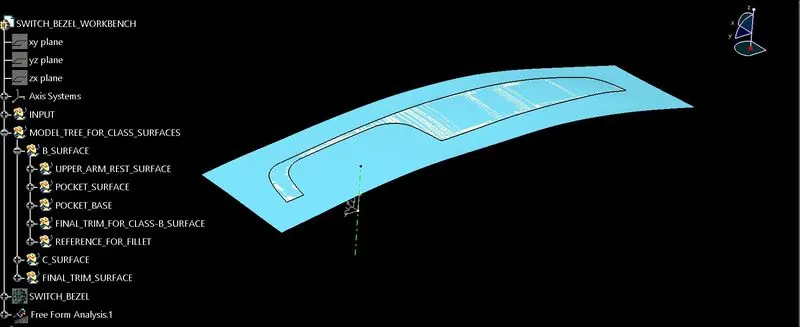
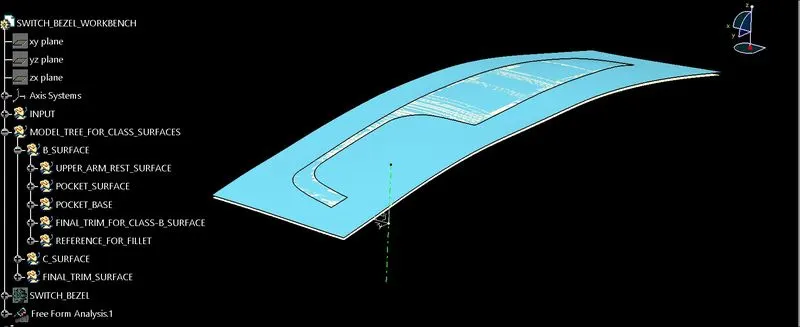
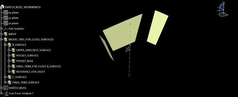
POCKET SURFACE CREATION:
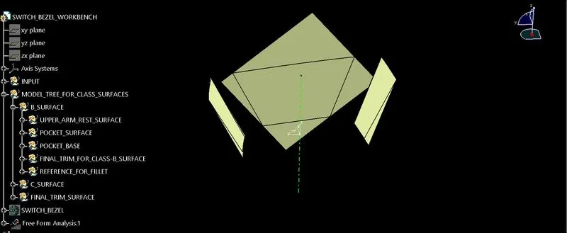
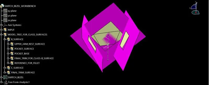
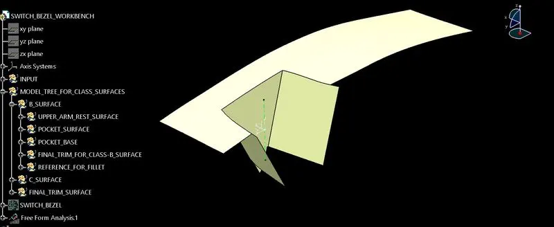
- First with the extract command the pocket inclined surface will be created.
- Now Un-trim the surface to get the straight edge surface.
- Now extrapolate the surface.
- After extrapolation, trim the surface.
- Now offset it by 2.5mm distance.
POCKET BASE SURFACE CREATION:
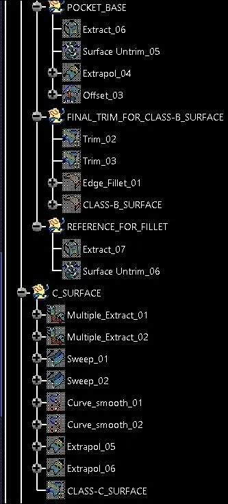
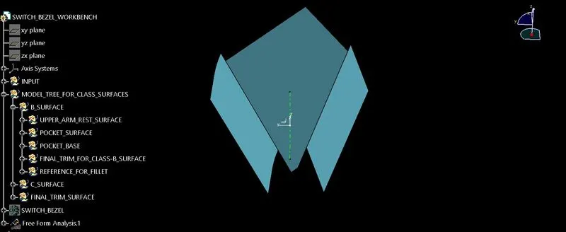
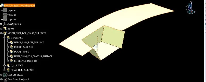
- First with the extract command the base surface will be created.
- Now Un-trim the surface to get the straight edge surface.
- Now extrapolate the surface.
- Now offset it by 2.5mm distance.
FINAL CLASS-B SURFACE CREATION:
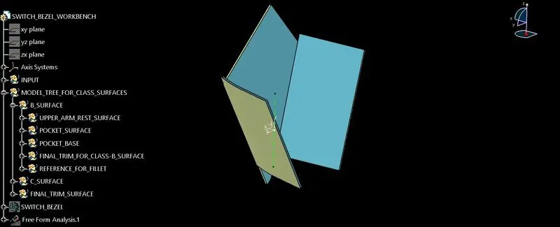
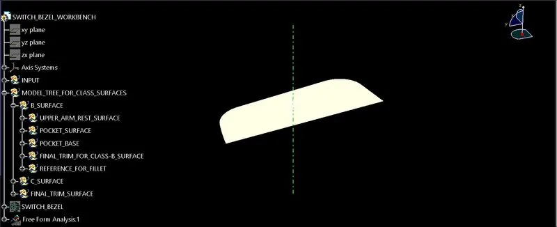
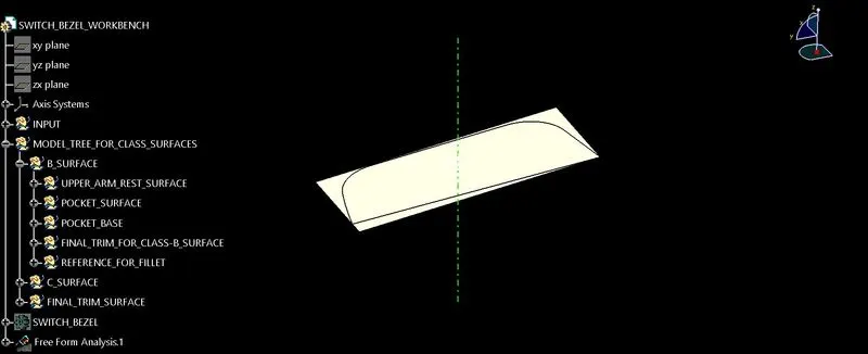
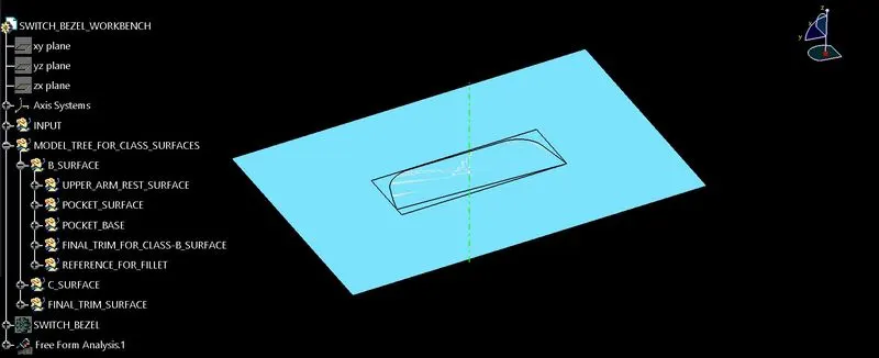
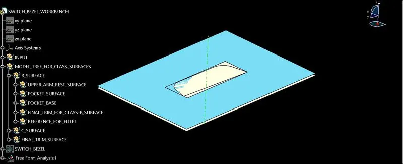
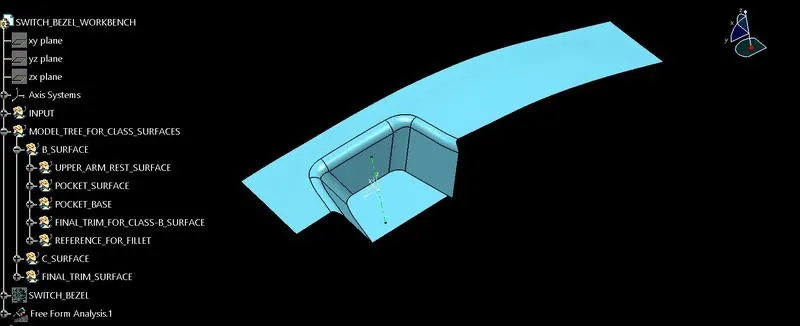
- Now trimming the Upper Arm Rest Surface with the Pocket Surface and then trim the Pocket Base Surface with the achieved surface.
- Finally by providing fillets on the achieved trimmed surface Class-B Surface is created.
FOR CLASS-C SURFACE CREATION:
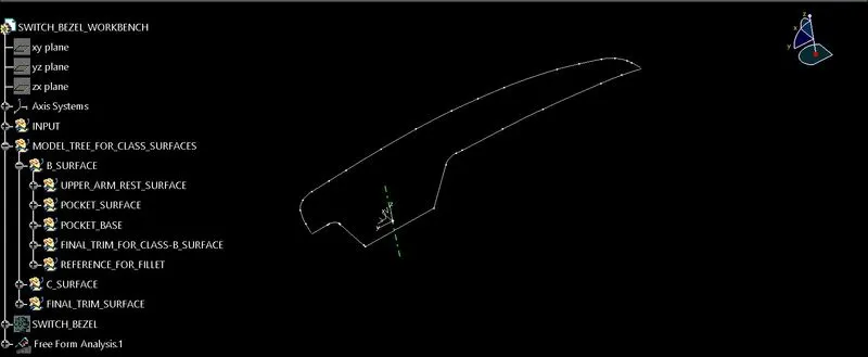
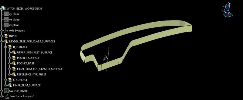
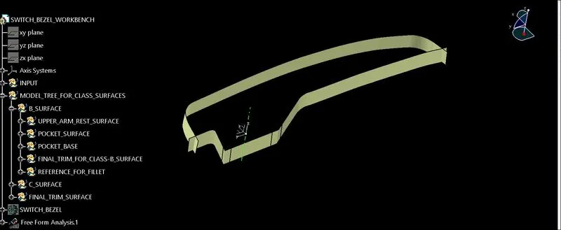
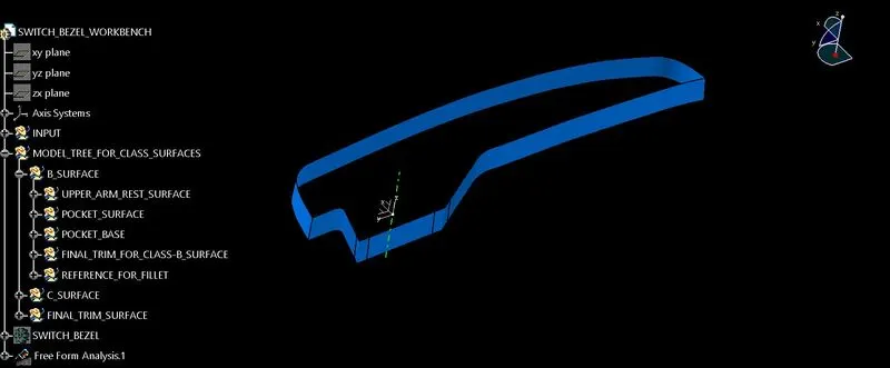
- First by using the boundary command creating the outer lines, the boundary of the class-A surface.
- Now creating Class-C surface with the sweep command using ‘With Draft Direction’.
- The surface achieved has so many small patches, by using smooth curve command removing the patches.
- It can be seen that at the end edges there is a gap, so to remove it first extrapolate the edges and then trim it.
- Finally Class-C Surface is achieved.
FINAL SWITCH BEZEL SURFACE CREATION:
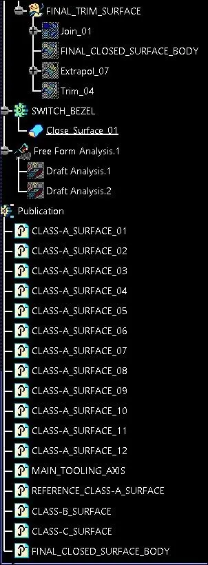
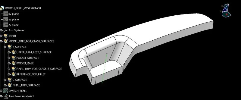
- Now with join command, join the Class-A and Class-C surfaces.
- After joining of Class-A & Class-C surfaces trim the achieved surface with the Class-B surface.
- Finally the closed surface body of the component is achieved in the surface design.
- Now move to part design with the close surface command, solidifying the component.
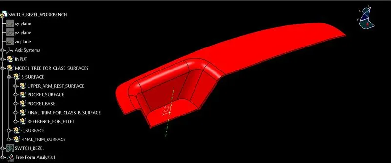
FOR DRAFT ANALYSIS CREATION:
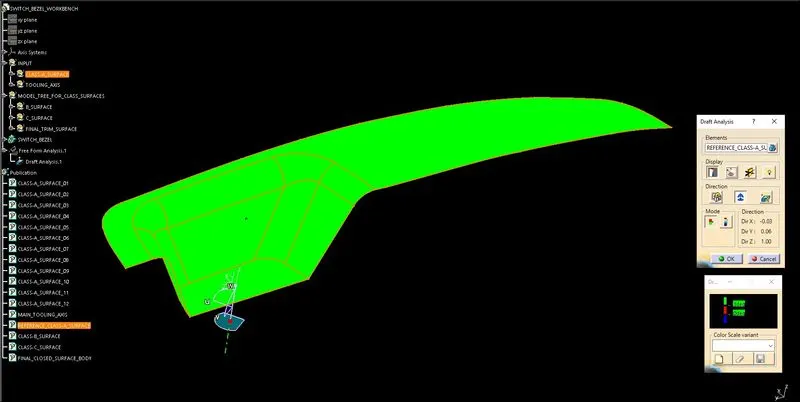
- First set material mode, now click on the draft analysis.
- After opening an interface of draft analysis, click on the symbol of datum/compass align it with the tooling axis.
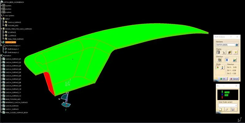
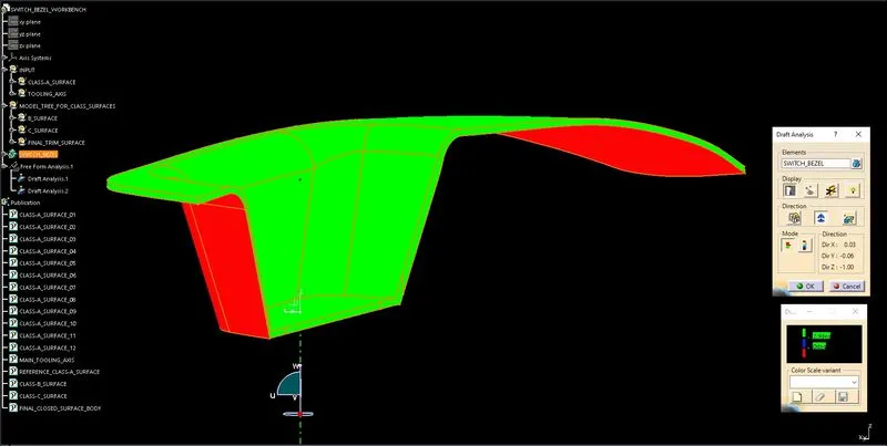
- Click on the surface and see that the surface is within the permissible limit of the draft values.
- Be ensuring that the surface should be green and if not flip the direction of the datum/compass it will turn into green.
- And after flipping the direction still not the draft analysis is not working, close the command and delete the 'Free From Analysis' and perform the process, it will start working.
- And if found that some area is still not turning into green, check the geometrical set or set the tooling axis with different values.
Gomertry and Surface Operations:-