Week 9 - Challenge 1 - Base Bracket Design
BASE BRACKET WORKBENCH
Objectives:- To create BASE BRACKET COMPONENT model using the Class-A Surface. It’s a plastic component so by keeping in mind all engineering constraints the model will be designed. This starts with the TOOLING AXIS for the Class-A surface should be created. After creation of tooling axis DRAFT ANALYSIS should be done on the Class-A surface and so on.
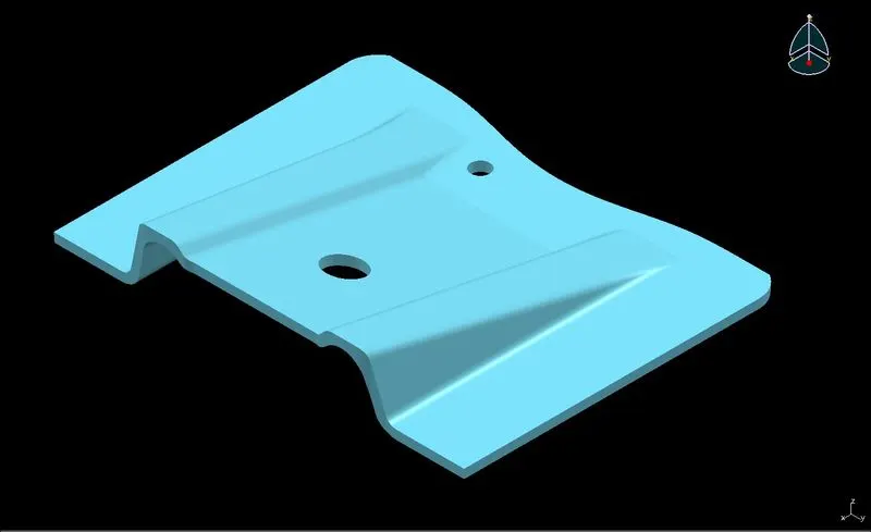
Introduction:-
Class-A Surface: It is an outermost surface which is developed by the designers and it is provided as an input to the modeller to work on it.
Class-B Surface: It is a surface at a certain thickness from the Class-A Surface.
Class-C Surface: It is a surface that joins the Class-A and Class-B Surfaces.
Orientation Views:- Front, Side, Top and Isometric Views.
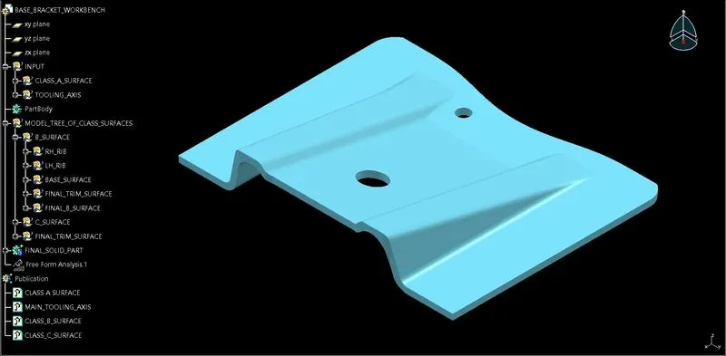
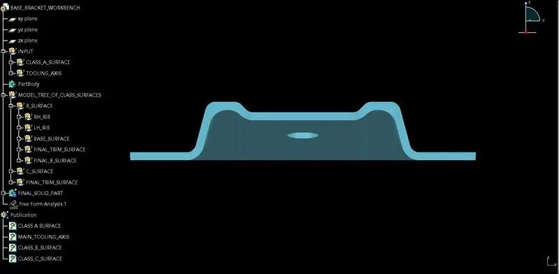
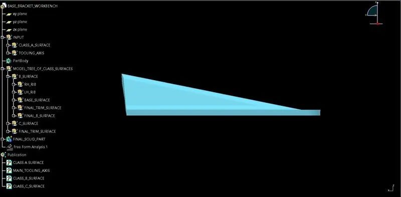
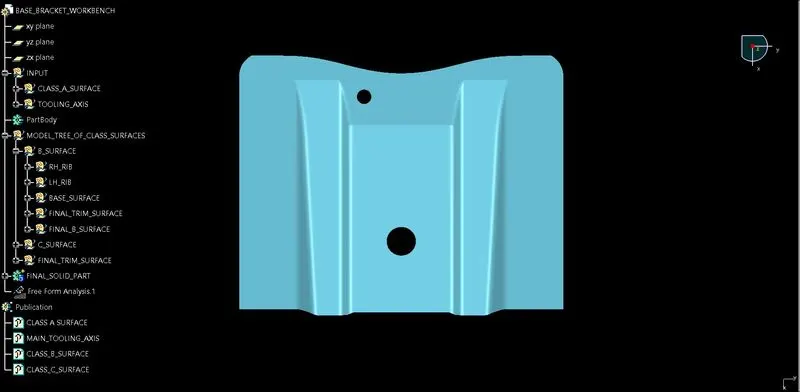
Commands or tools were used to create a closed surface/solid model, performing on the Class-A surface:
INTERSECT >> DRAFT ANALYSIS >> EXTRACT >> UN-TRIM >> EXTRAPOLATE >> TRIM >> OFFSET >> EDGE FILLET >> BOUNDARY >> SWEEP >> JOIN >> CLOSED SURFACE (Part Design)
FOR TOOLING AXIS CREATION:-
- First creating a point using point command with the reference of circular hole.
- Now creating a dummy tooling axis with the line command using ‘point & direction’.
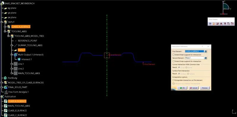
- Now using the intersect command, putting the YZ plane as an input and we achieved a boundary line at a Class-A surface.
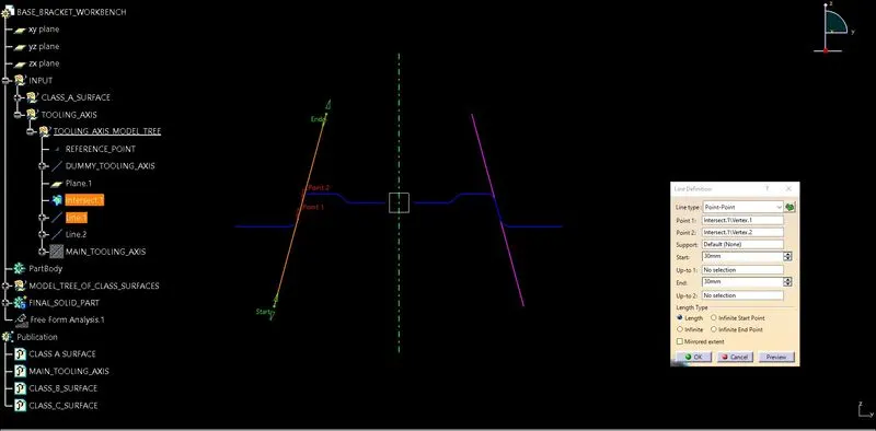
- Creating a line on the achieved boundary line with the line command using point to point.
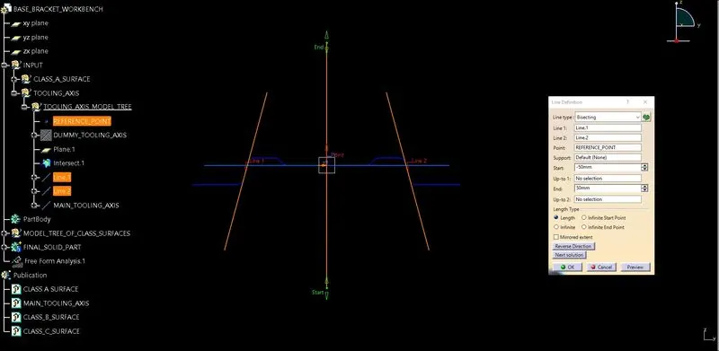
- Finally creating TOOLING AXIS line with the line command using bisecting.
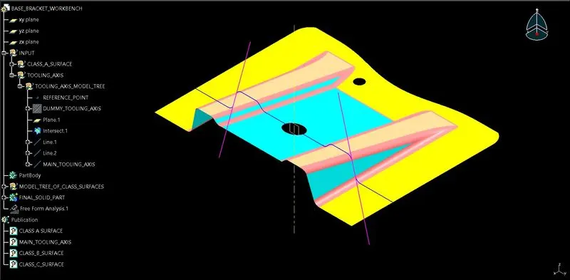
FOR DRAFT ANALYSIS CREATION:-
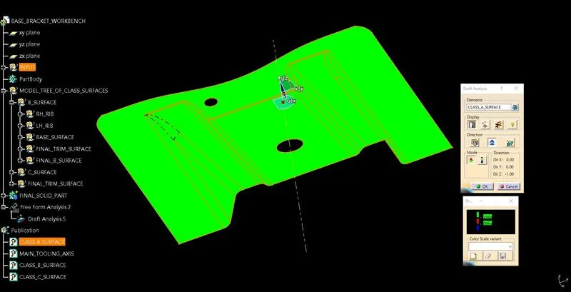
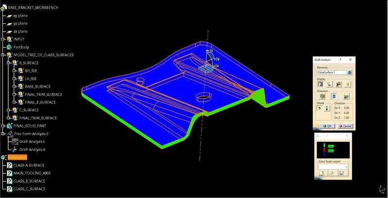
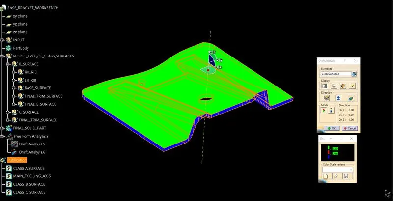
- First set material mode, now click on the draft analysis.
- After opening an interface of draft analysis, click on the symbol of datum/compass align it with the tooling axis.
- Click on the surface and see that the surface is within the permissible limit of the draft values.
- Be ensuring that the surface should be green and if not flip the direction of the datum/compass it will turn into green.
- And after flipping the direction still not the draft analysis is not working, close the command and delete the 'Free From Analysis' and perform the process, it will start working.
FOR CLASS-B SURFACE CREATION:-
RIBS SURFACES CREATION:-
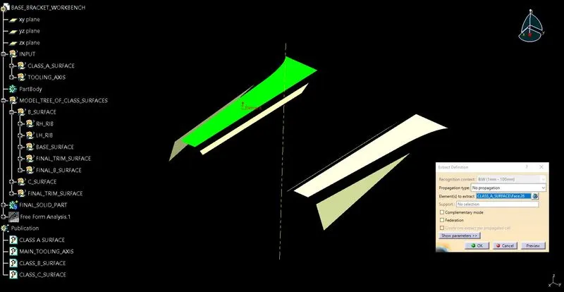
- First with the extract command the rib surface will be created from the Class-A surface.
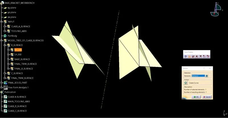
- After extraction, Un-trim command is used to remove the sharp or curved edges and creating straight edges.
- Now extrapolate command is used to extend the boundaries.
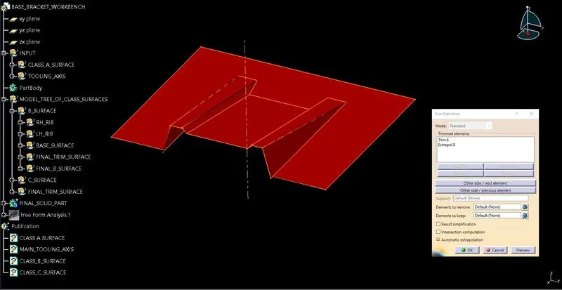
- Trim command is used to achieve the desired shape.
- As the thickness of the component is 2.5mm, so by using offset command the achieved desired shape is now Offset up to 2.5mm distance.
- Now repeating the same process for the second rib.
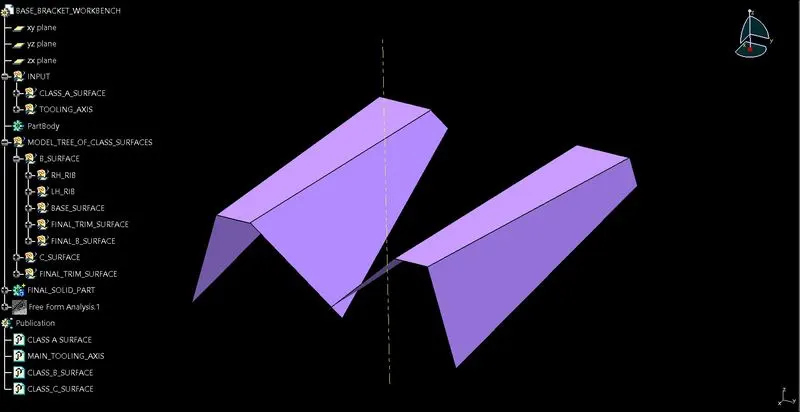
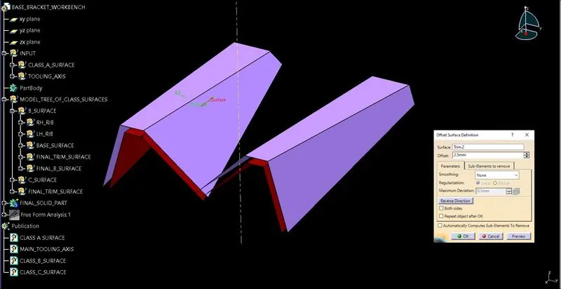
FOR BASE SURFACE CREATION:-
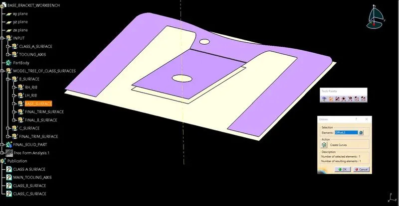
- First with the extract command the base surface will be created.
- Now Un-trim the surface to get the straight edge surface.
- Now extrapolate the surface.
- Now offset it by 2.5mm distance.
- Now trim the base surface with the rib surfaces to get the exact offset shape of the Class-A surface.
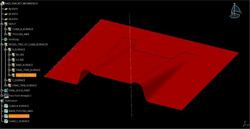
- Now filleting the edges to get the final Class-B surface.
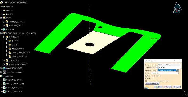
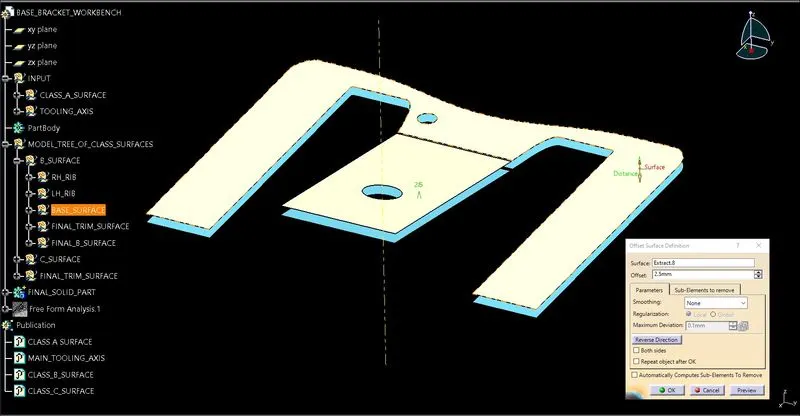
FOR CLASS-C SURFACE CREATION:-
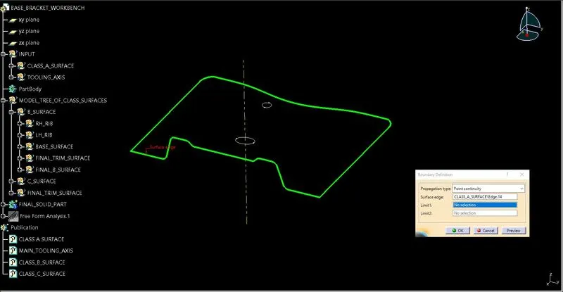
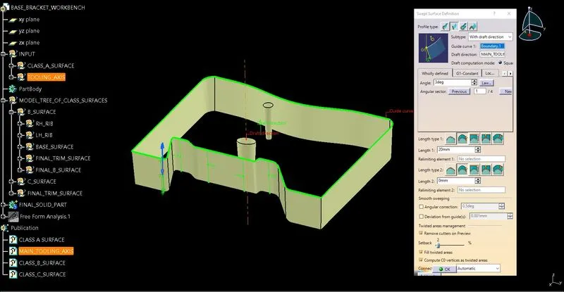
- First using the boundary command creating the outermost boundary of the class-A surface.
- Again using the boundary command for the boundary of the holes on the class-A surface.
- Now creating Class-C surface with the sweep command using ‘With Draft Direction’.
FINAL BASE BRACKET CREATION:-
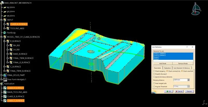
- Now with join command, join the Class-A and Class-C surfaces.
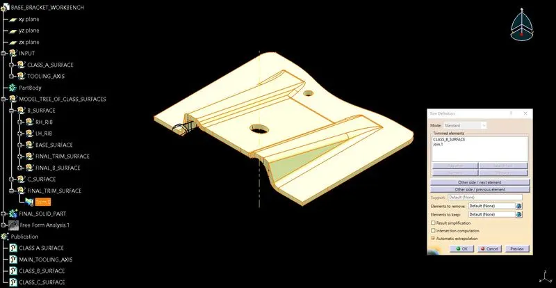
- After joining of Class-A & Class-C surfaces trim the achieved surface with the Class-B surface.
- Finally the closed surface body of the component is achieved in the surface design.
- Now move to part design with the close surface command, solidifying the component.