Week 12- Final project
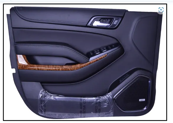
YOUR PROJECT : DEVELOPMENT OF A DOOR TROM PANEL .
AIM : TO CREATE A SOLID BODY OF SIDE DOOR PLASTIC TRIM INCLUDING THE ENGINEERING FEATURES USING CATIA V5 TOOL USING GIVEN A CLASS SURFACE AND MASTER SECTION AND ADDING THICKNESS.
INTRODUCTION: SIDE DOOR PLASTIC TRIM AN INTERIOR COMPONENT ATTACHED TO THE INNER SIDE OF THE DOOR. THIS PRODUCT DOES MORE THAN MERELY IMPROVE.
side door plastic trim :
an interior component attached to the inner side of the door, this product does more than merely improve the appearance of the vehicle interior .rather, it is a vital module component that creates a more comfortable interior by providing a variety of accouterments and functions.
CONCEPT / IDEATION :
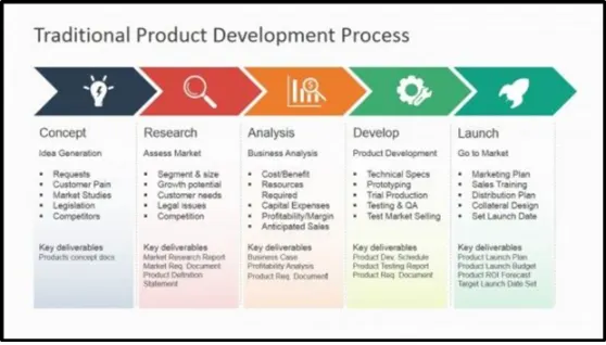
THIS IS THE CONCEPT AND IDEATION STAGE DURING WHICH A PRODUCT 'S FUNCTIONAL AND PERFORMANCE REQUIREMENTS CAN BE DEFINED ALONG WITH BUYER PERSONAS or the voice of the customer '. customer requirements and innovative functionality design ideas are floated and explored freely to find compelling potential solutions that answer an identified market need.
FEASIBILITY STUDY AND DESIGN PLANNING :
the feasibility phase allows management to evaluate a project's potential success. reviewing and refining the business case from various angles. during this phase. the project team reviews product design concepts. they then select the design that best ffulfillsthefulfillsdefinedtheir their requirements. now, the detailed, exhaustive project requirements are assembled that will guide the design and development phase.
DESIGN AND DEVELOPMENT:
in this phase, formal engineering specifications are created. verification and validation plans are developed for the future. these are the final quality checks that will systematically determine that all agreed deliverables are present and working in the end product. the product is then developed against the designs, with regular checks made throughout the process to assess and mitigate the risk of its failure for the end - user and the project itself.
TESTING & VERIFICATION
comprehensive testing of the final product takes place to evaluate the robustness of the design and its ability to meet customer and performance requirements. verification takes place against the design requirements identified in stage 2.
VALIDATION & COLLATERAL PRODUCTION :
validation takes place against the customer needs that have been identified at the ideation stage.
collateral is finalized and prepared to support the manufacture and launch phase.
MANUFACTURE/ LAUNCH
plans, specs, and other relevant documentation are transferred to the manufacturer for production, or software products and updates are released to the customer. Marketing and launch plans are finalized and activated. software products are released to customers electronically as updates or downloads.
IMPROVEMENT :
the new product becomes part of the company's portfolio. ongoing product management ensures the product is subject to continuous upgrades and improvement. CAPA processes are in place to feed into these actions.
The stages of the design life cycle are
Concept sketches :
Concept sketches are rough ideas of freehand sketches obtained through styling team and will be used to prepare the model .it is usually done through pen and paper and the painting software .this is will be used to generate the concept for preparing the model by incorporating various and styling and information obtained through the stake holders
Class improvement: A
After finalizing the concept the sketches are usually worked in software such as auto desk alias to create class A surface.
Clay modeling :
The Class A surface is concurrently worked by clay modelers to brainstorm and benchmark the styling of the product and later the concept is validated by bringing by up a rough clay model and then it is passed on to the design team for the preparation of new product design (npd) cad .
NPD CAD :
this where the development of surfaces to parts in CAD kick off and design engineers involvement is vital in this stage . the designers will work on the input class A surfaces which are validated from the feasibility team . the procedure followed in creation of the plastic new product design are
class A
improvement classA
TOOLING AXIS
B- SURFACE CREATION
C-SURFACE CREATION
CLOSED BODY CREATION
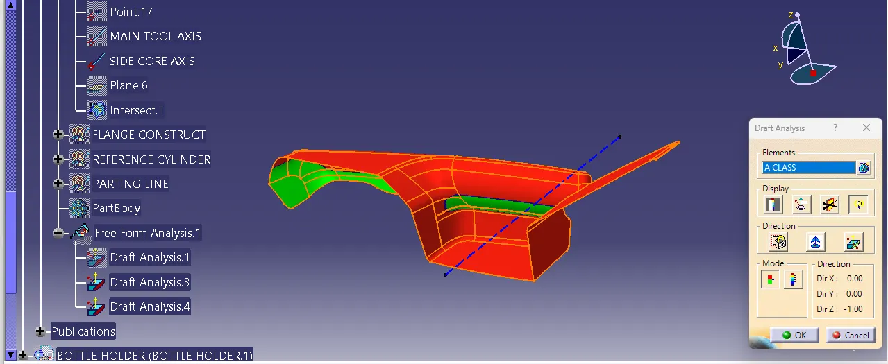
DRAFT ANALYSIS
FRIST CREATION CLOSE BODY AND SURFACE IMPROVEMENT THE SURFACE :
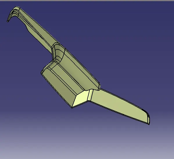
ARM REST :
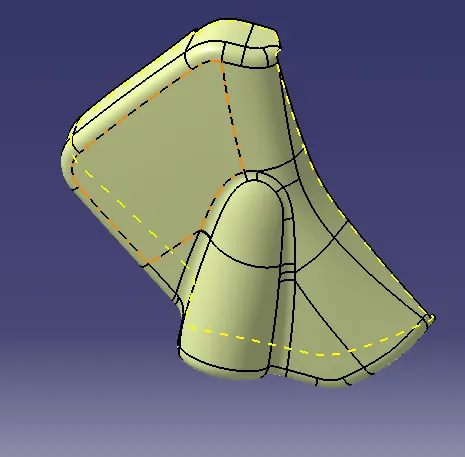
BOTTLE HOLDER :
LOWER SUBSTRACT:
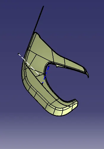
MAP POCKET :
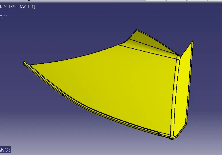
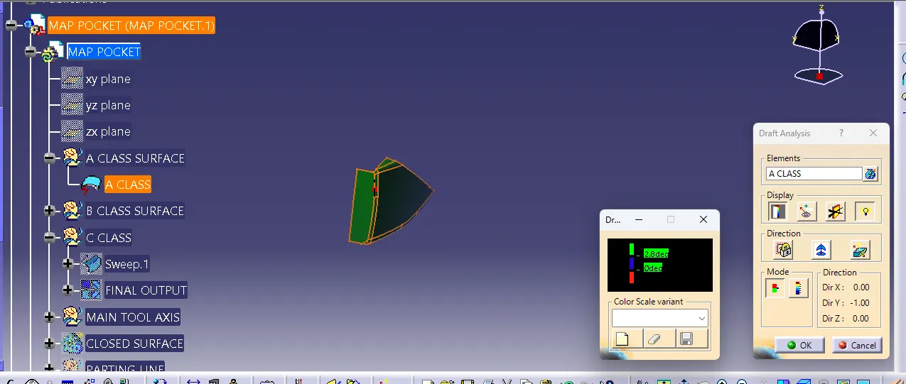
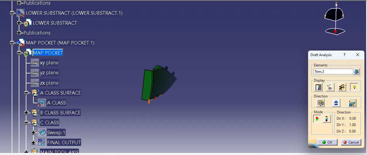
DRAFT ANALYSIS :
ARM REST MANI TOOLING AXIS : 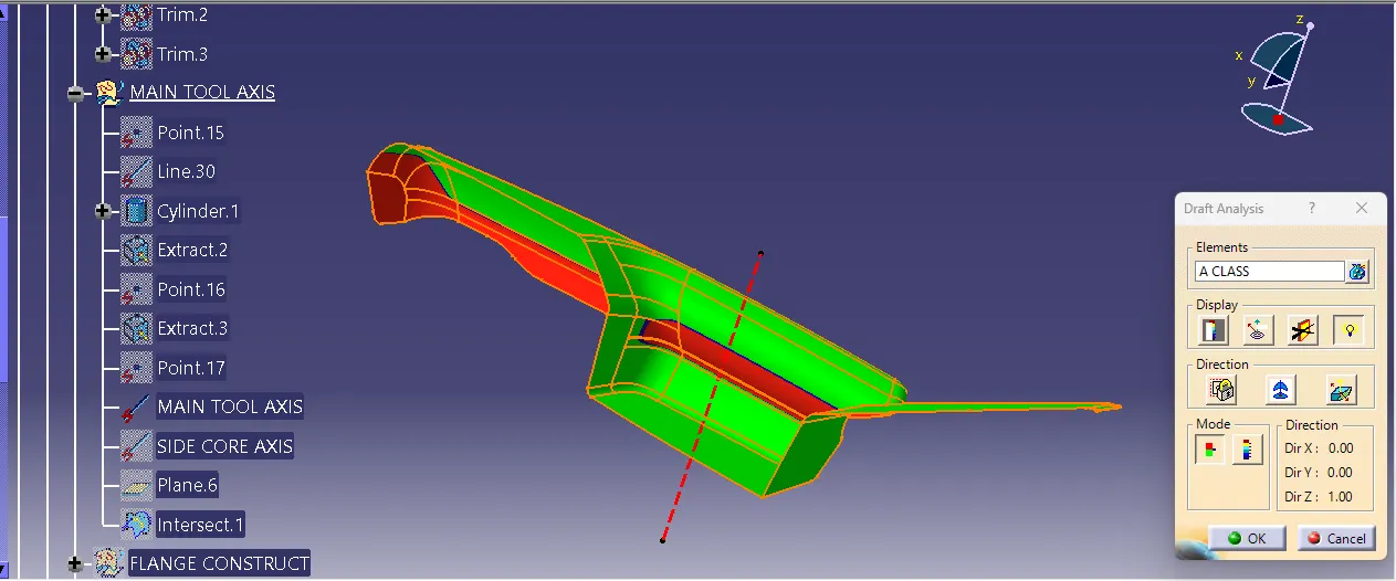
ARM REST SIDE TOOLING AXIS :
BOTTLE HOLDER :
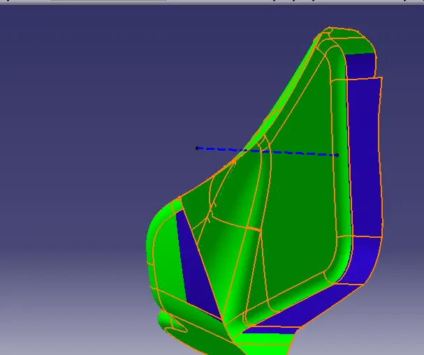
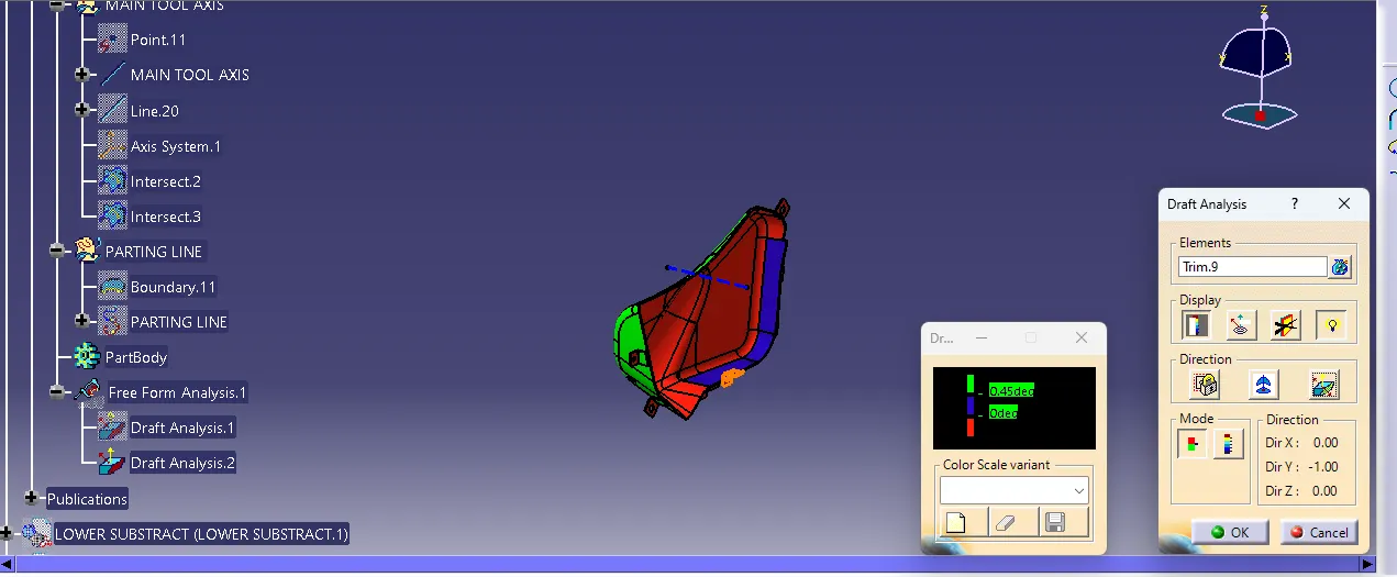
LOWER SUBSTRACT:
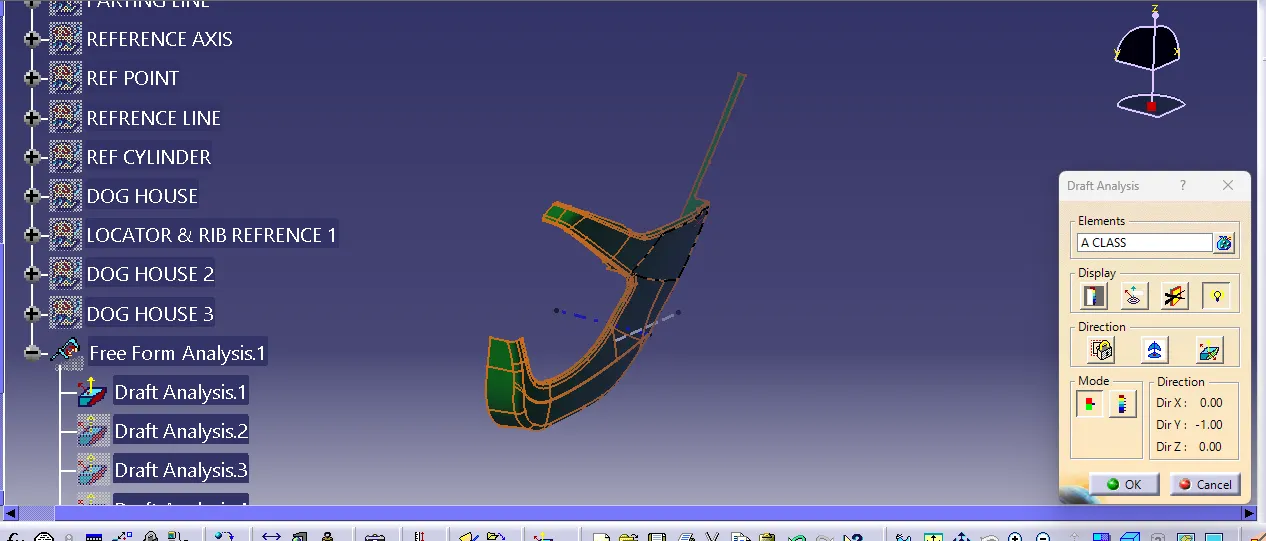
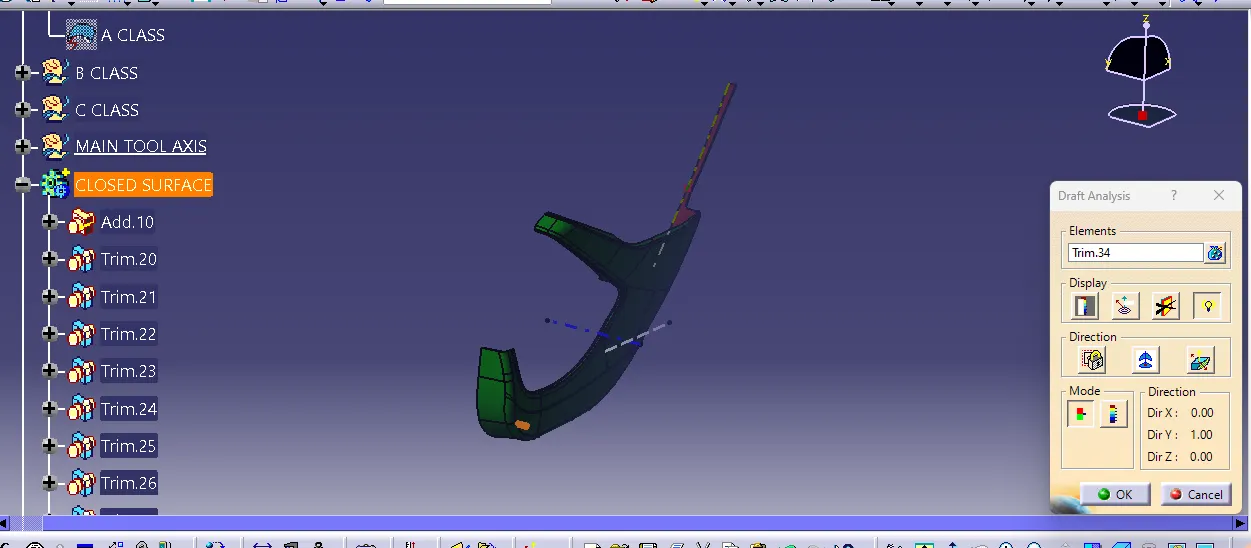
DOG HOUSE-
. THE TWO MAIN PURPOSES OF A DOG HOUSE ARE TO AVOID SINK MARKS AND TO HOUSE VARIOUS OTHER ENGINEERING FEATURES LIKE SCREW BOSS, LOCATORS,PUSH CLIPSETC.
IN THIS CASE, THE DOG HOUSE IS DESIGNED TO HOUSE THE PUSH CLIPS AND THE 4 WAY LOCATOR .THE DOG HOUSE DESIGNED FOR THE PUSH CLIP FEATURES A SLOT ON THE TOP FACE TO ACCOMMODATE THE PUSH CLIP .
THE DOG HOUSE SHOULD FOLLOW CRETAIN DESGIN RULES WHICH ARE STATED BELOW
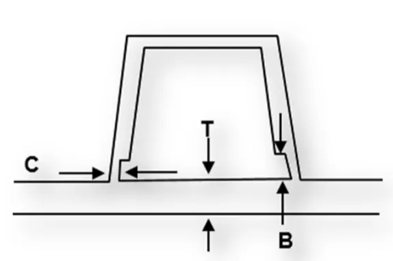
DOG HOUSE WALL THICKNESS AT THE INTERSECTION OF THE PART WALL (C)SHOULD BE 40% OR LESS THAN THE MANI WALL STOCK(T).
THE HEIGHT OF (B) SHOULD BE BETWEEN 3.0-6.0MM
OUTER SURFACE OF DOG HOUSE MUST HAVE A DRAFT ANGLE OF 3 DEGREES.
INNER SURFACE OF DOG HOUSE MUST HAVE A DRAFT ANGLE OF 0.5 DEGREES.
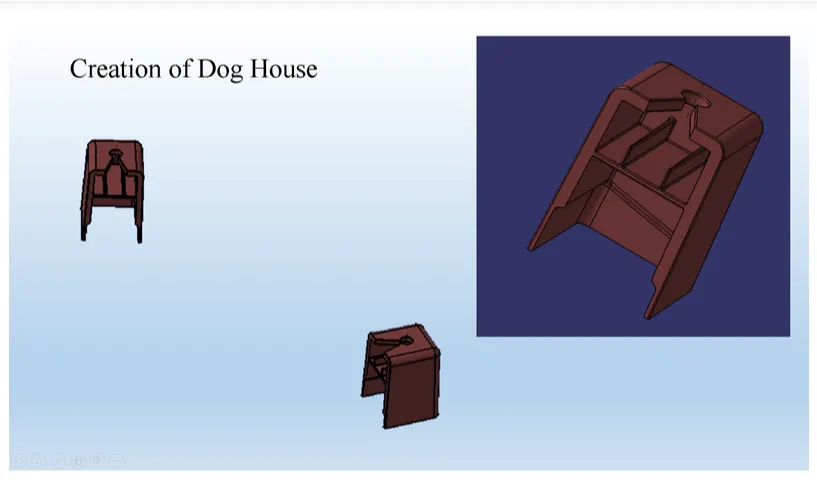
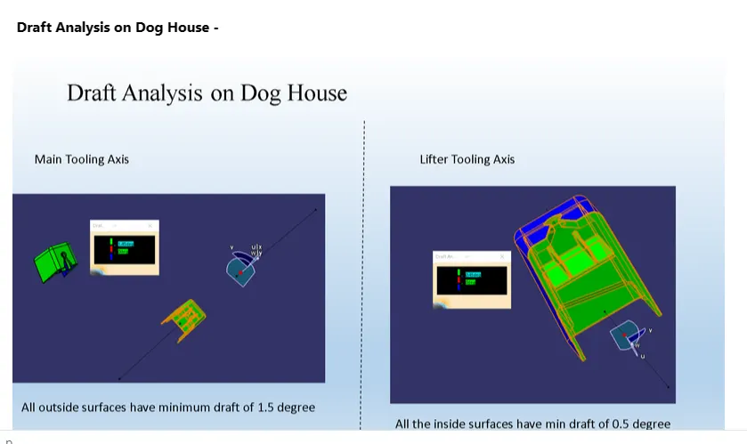
FROM ABOVE DRAFT ANALYSIS WE NOTICED THAT OUTER SURFACES OF DOG HOUSE HAVE MINIMUM DRAFT OF 1.5 DEGREE AND INNER SURFACES WITH MINIMUM DRAFT OF 0.5 DEGREE
FINAL ASSEMBLY-
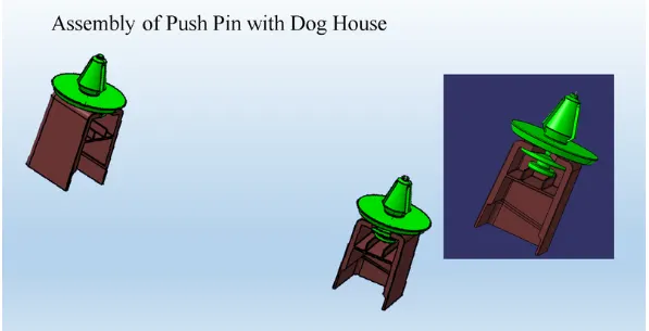
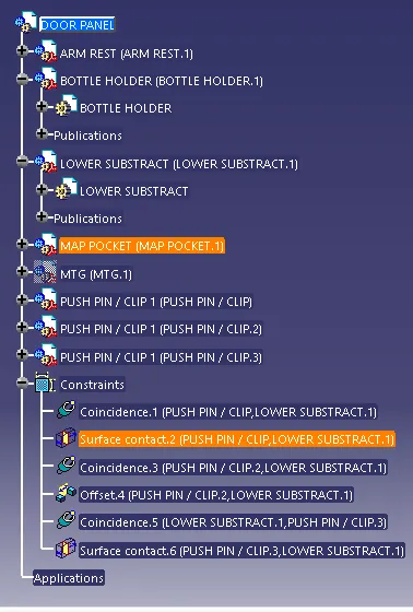
FOR FINAL ASSEMBLY OF DOOR TRIM PANEL WE HAVE TO CONSTRIN ALL PARTS TOGETHER .
FOLLOWING IMAGE SHOWS THE ASSEMBLY OF PUSH PIN WITH DOG HOUSE .
TREE STRUCTURE:
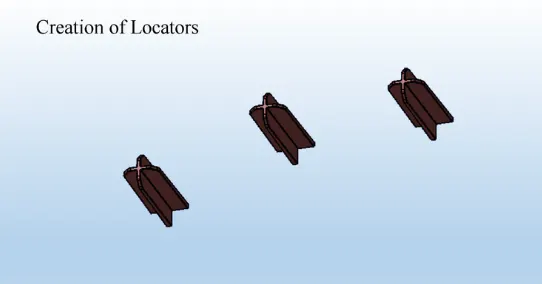
CREATION OF LOCATORS:
LOCATORS -
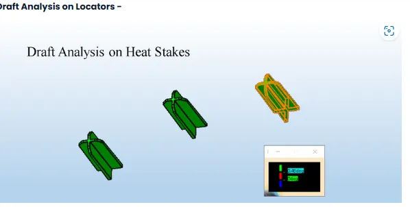
THE MANI PURPOSE OF LOCATORS IS TO FACILITATE PROPER LOCKING OF TWO COMPONENTS TOGETHER WHILE ASSEMBLING AND ARREST THE MAXIMUM DEGREES OF FREEDOM POSSIBLE
THESE LOCATORS ARE SIMILAR TO GUIDE PINS PROVODED IN MOULD .
THE TWO TYPES OF LOCATORS USED ARE TWO WAY LOCATOR AND FOUR WAY LOCATOR.
WE HAVE POSITIONED THREE 4 WAY LOCATORS IN OUR MODEL WHICH MEET THE RIB DESIGN CRITERIA.
CONCLUSION :-
FROM THIS PROJECT I HAVE LERANED HOW TO CRATE CAD MODEL FOR PLASTICS PARTS BY CONSIDERING DESIGN RULE . BY DOING THIS PROJECT ON CATIA V5, I GET VERY WELLFAMILIAR WITH PART WORKBENCH , ASSEMBLY WORKBENCH . ALSO I GOT CONFIDENCE IN HANDLING DIFFERENT FEATURES OF ALL WORKBENCHES. ALONG WITH THIS , IGET IDEA OF HOW TO DESIGN A PART BY CONSIDERING MANUFACTURING AND ASSEMBLY ASPECT.