Week 12- Final project
AIM: -
To create a CAD model for door trim panel's parts by considering the given inputs of class A surface along with master section by following the design rules followed in OEM companies.
OBJECTIVES: -
- To create individual tooling axis for the parts and perform draft analysis on the class A surface
- To form a solid body from the given class A surface.
- To decide an attachment strategy for the part and create engineering features in reference from the master section provided.
- To perform draft analysis on the solid part model with all engineering features.
- To assemble all the components together to obtain the final trim.
- Create the parting line
Door Trim Components:
- Arm Rest
- Bottle Holder
- Lower Substrate
- Map Pocket
- Push Pin
B-Side Engineering Features:
- Heat Stakes
- Ribs
- Locators
- Dog-House
1. Arm Rest:
- Class A Surface:
Class A is an aesthetic surface with the highest quality finish. Most Class A Surfaces for an Automotive Component are made using 'Autodesk-Alias' based on the final Concept-Sketch.
All Class A surfaces should have 'Curvature-Continuity', meaning the continuity between the surfaces should share the same boundary. It is taken as a reference by the Automotive Plastic Designer to create 'Class B' and 'Class C' Surfaces.
- Class B Surface:
The Class B Surface resides below the Class A Surface at a certain thickness. It is created using Engineering Principles that consist of all the necessary features such as Ribs, Bosses, Snaps, etc. This surface isn't visible to the observer from the outside.
- Class C Surface:
The Class C Surface is the surface created between the Class A and Class B surfaces to join them with each other.
Now, we will begin by checking the State of Connectivity for the Class A Surface and ensure that there are no gaps between the surfaces as all the surfaces should be joined well together with each other and shouldn't consist of any discontinuities between them.
Arm rest Class A Surface:
The given class A surface has a small patch in one area,so the class A surface needs to be improve.
After class A surface improvement
Procedure for creating the tooling axis
Tooling axis represents the opening and closing of the mold core and cavity during the manufacturing of the components. A plastic product designer should consider the best tooling direction to cutdown the cost of the component very less.
Method opted for creating tooling axis for the door handle
- Check the best tooling direction for the given surface.
- We can find out the best tooling direction by cross checking all the three axes.
- Here we can find out that the best tooling direction for the Arm rest class-A surface is along Z-axis direction.
Creating tooling axis
- We should create a Dummy tooling axis first by creating point and line.
- Extract the existing class A surface and create a dummy tooling axis for reference.Highlighted megentha colour is main tooling axis.
Main tooling Axis Side core tooling Axis
Draft analysis for the given CLASS-A surface
The Draft Analysis is a command enables you to detect if the part you drafted will be easily removed. This type of analysis is performed based on colour ranges identifying zones on the analysed element where the deviation from the draft direction at any point, corresponds to specified values.
Draft analysis is done after determining the tooling axis, draft analysis is used to check whether the minimum draft (3 degrees) is maintained or not.
- Procedure for performing the draft analysis are as follows
- Change the view mode of the component to be in customized parameter mode and then select the shading mode as materials.
- Then open the featured draft analysis tool from the insert menu.
- Then click on use the compass to define the current drafting direction without activation the compass and then activate the compass in the dialogue box drag and align the compass on the Tooling axis.
- Then lock the draft direction and perform draft analysis by clicking on the component.
- The green colour shows the positive daft tooling direction and the given surface passes the draft analysis.
- Click on the analysis under the running point to check the draft analysis on the individual faces. It shows how much draft on specific points when we move the cursor point.
Class A Draft Analysis: Class A side core Draft Analysis:
SURFACE-B CREATION
Class-B surface means thickness of a part it is not visible and is inside part. In other words, Class-B surface is a surface below a certain thickness from the class-A surface. This is the surface that contains engineering aspects of a model.
- Offset the class-A surface to 2.5mm inward direction.
- After offset ,There will be some open patches in the fillet area ,Found an open patches as shown in below images.
Class B improved surface
Creation of C Surface
- Surface that joins class-A and class-B surfaces is class-C surface. Class C is often specified for interior surfaces not readily visible, surfaces that will be covered by another part when assembled
- Since it is a class-A surface with sharp corners, we cannot simply create the class-A boundary curve and sweep it at one shot.
- Hence, we need to create smaller boundary and then create sweep,Multi section surface.
- If the surface is perpendicular to the tooling axis we have to provide 3 degree draft with reference to the tooling direction.
Final C Surface
Final A-C JOIN
Final A-C&B trim
Close Solid Surface:
START -> MECHANICAL DESIGN -> PART DESIGN -> SURFACE FEATURE -> CLOSE SURFACE
Flange creation using master section
- In case of te door arm rest we need to folow the master section provided for the flange creation
- The thickness of the flange is equal to the thickness of the plastic component that is 2.5 mm
- To use the master section as reference and create the sketch and generate the surface, then make ticken surface.
- The draft provided is 0.5 deg
- Apply requierd fillets on all the sharp edges.
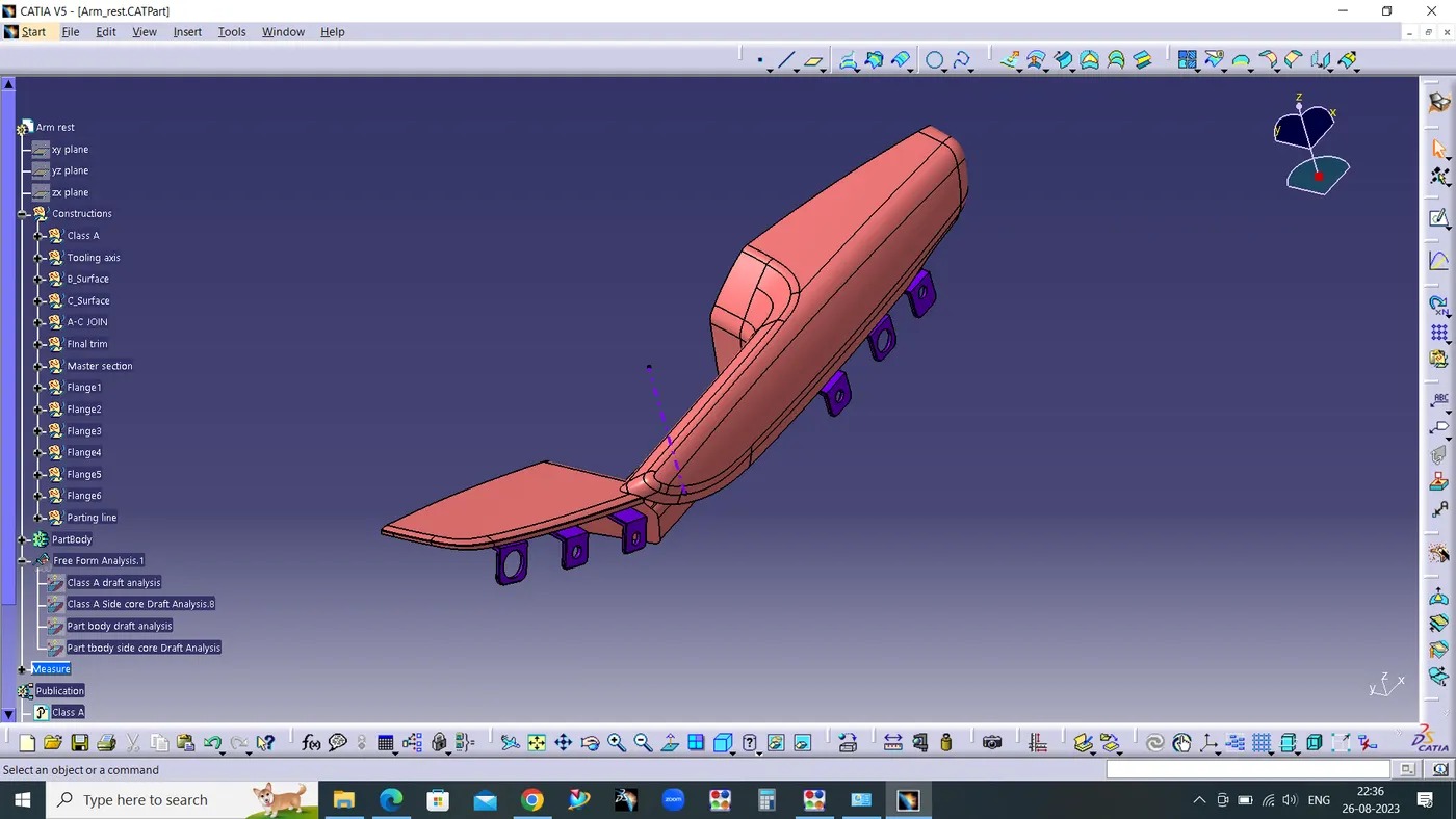
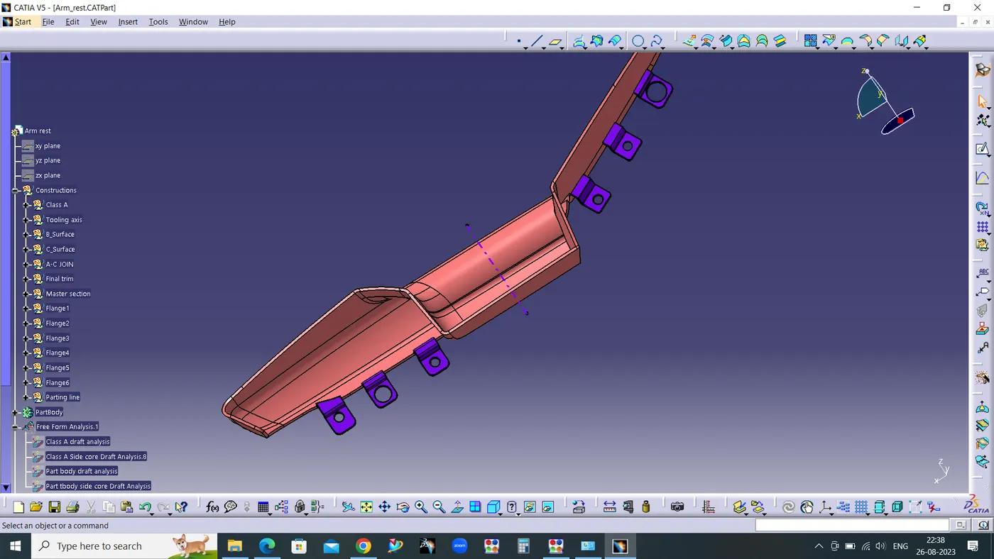
Final Close Body Draft Analysis:
Procedure for performing the draft analysis are as follows
- Change the view mode of the component into customized parameter mode and then select the shading option as material mode.
- Then open the featured draft analysis tool from the insert menu -> Analysis.
- Then click the compass and drag the axis to define the current drafting direction to tooling axis.
- Then lock the draft direction and perform draft analysis by pick the component.
- The green colour shows the positive daft tooling direction and the given surface passes the draft analysis.
Parting line
-
Injection molding parting line or mold split line is a line or surface on an injection molded part where the two halves of the mold meet. The mold is split along the parting line to allow for the injection of molten plastic and the release of the finished part.
2. Bottle Holder
Bottle Holder Class A Surface:
Procedure for creating the tooling axis
Tooling axis represents the opening and closing of the mold core and cavity during the manufacturing of the components. A plastic product designer should consider the best tooling direction to cutdown the cost of the component very less.
Method opted for creating tooling axis for the door handle
- Check the best tooling direction for the given surface.
- We can find out the best tooling direction by cross checking all the three axes.
- Here we can find out that the best tooling direction for the Arm rest class-A surface is along Y-axis direction.
Creating tooling axis
- We should create a Dummy tooling axis first by creating point and line.
- Extract the existing class A surface and create a dummy tooling axis for reference.Highlighted megentha colour is main tooling axis.
Main tooling Axis
Draft analysis for the given CLASS-A surface
The Draft Analysis is a command enables you to detect if the part you drafted will be easily removed. This type of analysis is performed based on colour ranges identifying zones on the analysed element where the deviation from the draft direction at any point, corresponds to specified values.
Draft analysis is done after determining the tooling axis, draft analysis is used to check whether the minimum draft (3 degrees) is maintained or not.
- Procedure for performing the draft analysis are as follows
- Change the view mode of the component to be in customized parameter mode and then select the shading mode as materials.
- Then open the featured draft analysis tool from the insert menu.
- Then click on use the compass to define the current drafting direction without activation the compass and then activate the compass in the dialogue box drag and align the compass on the Tooling axis.
- Then lock the draft direction and perform draft analysis by clicking on the component.
- The green colour shows the positive daft tooling direction and the given surface passes the draft analysis.
- Click on the analysis under the running point to check the draft analysis on the individual faces. It shows how much draft on specific points when we move the cursor point.
SURFACE-B CREATION
Class-B surface means thickness of a part it is not visible and is inside part. In other words, Class-B surface is a surface below a certain thickness from the class-A surface. This is the surface that contains engineering aspects of a model.
- Offset the class-A surface to 2.5mm inward direction.
- After offset ,There is no patches in the fillet area.
Creation of C Surface
- Surface that joins class-A and class-B surfaces is class-C surface. Class C is often specified for interior surfaces not readily visible, surfaces that will be covered by another part when assembled
- Since it is a class-A surface with sharp corners, we cannot simply create the class-A boundary curve and sweep it at one shot.
- Hence, we need to create smaller boundary and then create sweep,Multi section surface.
- If the surface is perpendicular to the tooling axis we have to provide 3 degree draft with reference to the tooling direction.
Final A-C JOIN
Final A-C & B JOIN
Close Solid Surface:
START -> MECHANICAL DESIGN -> PART DESIGN -> SURFACE FEATURE -> CLOSE SURFACE
Close body draft analysis:
Flange creation using master section
- The thickness of the flange is equal to the thickness of the plastic component that is 2.5 mm
- To use the master section as reference and create the sketch and generate the surface, then make ticken surface.
- The draft provided is 0.5 deg
- Apply requierd fillets on all the sharp edges.
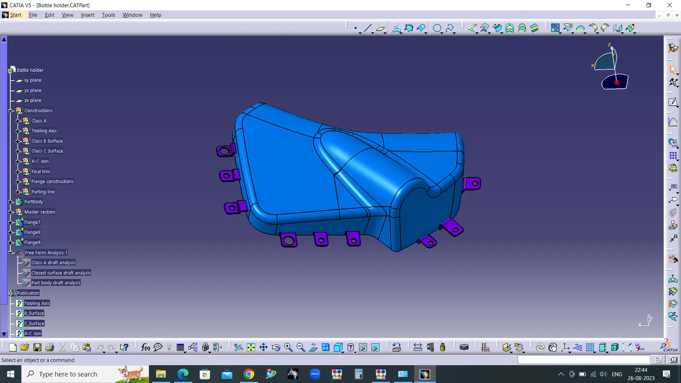
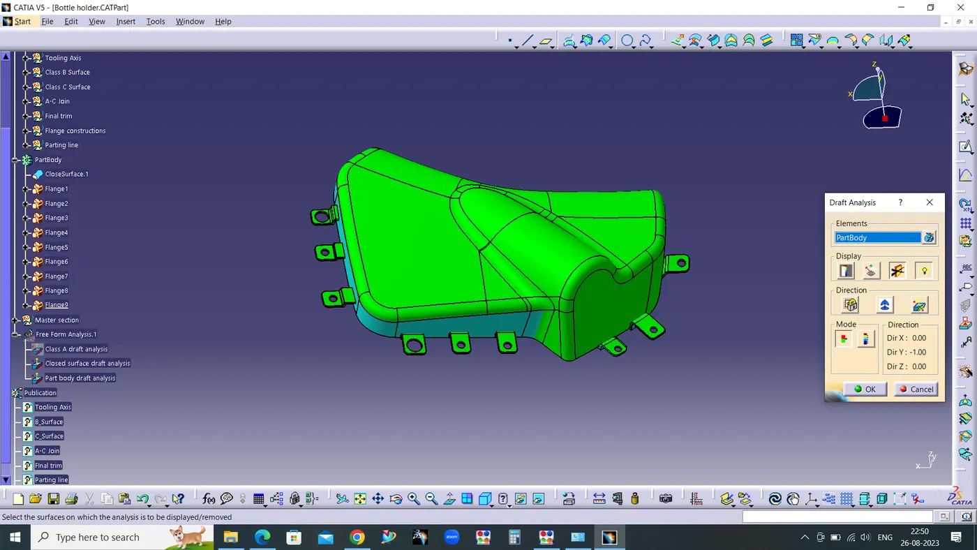
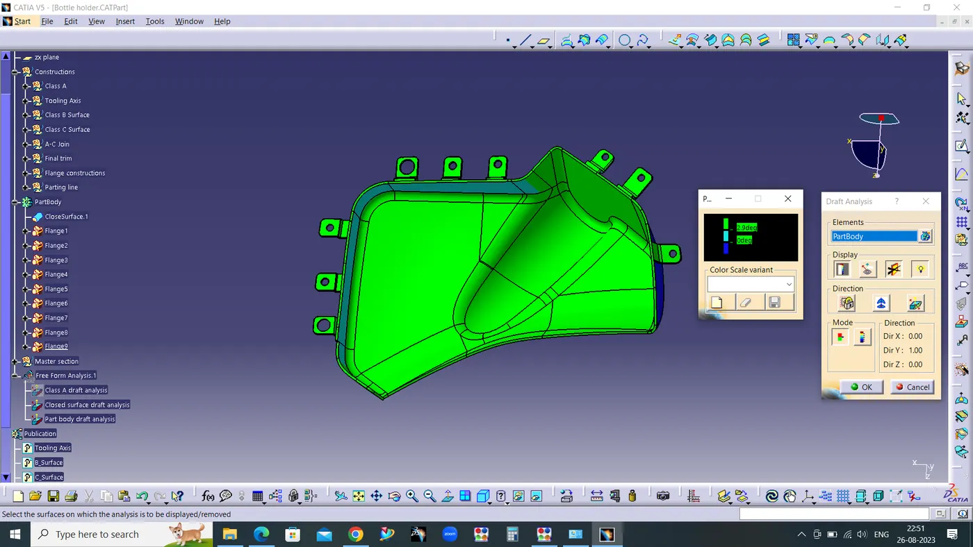
Final Close Body Draft Analysis:
Procedure for performing the draft analysis are as follows
- Change the view mode of the component into customized parameter mode and then select the shading option as material mode.
- Then open the featured draft analysis tool from the insert menu -> Analysis.
- Then click the compass and drag the axis to define the current drafting direction to tooling axis.
- Then lock the draft direction and perform draft analysis by pick the component.
- The green colour shows the positive daft tooling direction and the given surface passes the draft analysis.
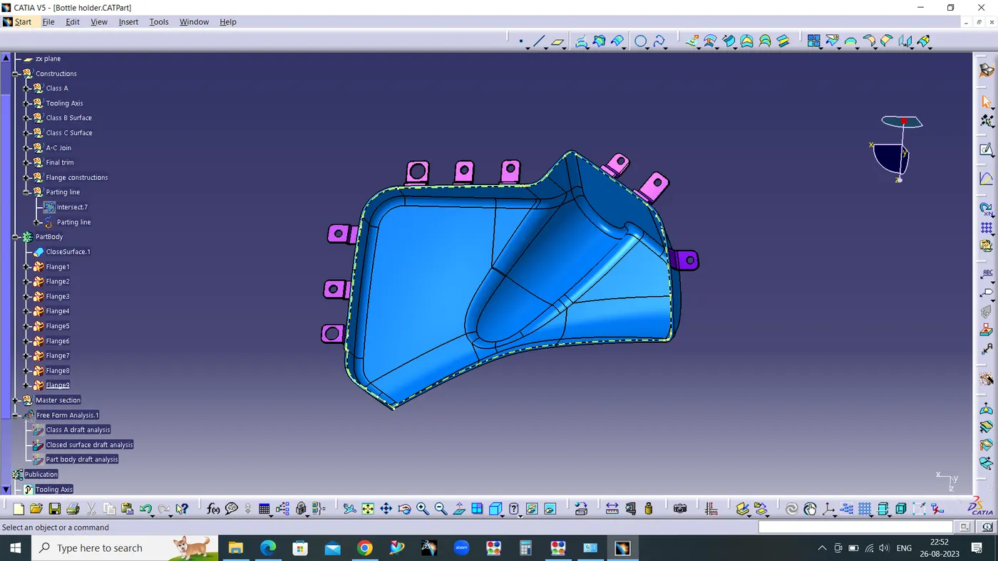
Parting line
-
Injection molding parting line or mold split line is a line or surface on an injection molded part where the two halves of the mold meet. The mold is split along the parting line to allow for the injection of molten plastic and the release of the finished part.
3.Lower Substrate
Lower Substrate class A Surface
Procedure for creating the tooling axis
Tooling axis represents the opening and closing of the mold core and cavity during the manufacturing of the components. A plastic product designer should consider the best tooling direction to cutdown the cost of the component very less.
Method opted for creating tooling axis for the door handle
- Check the best tooling direction for the given surface.
- We can find out the best tooling direction by cross checking all the three axes.
- Here we can find out that the best tooling direction for the Arm rest class-A surface is along Y-axis direction.
Creating tooling axis
- We should create a Dummy tooling axis first by creating point and line.
- Extract the existing class A surface and create a dummy tooling axis for reference.Highlighted megentha colour is main tooling axis.
Main tooling Axis
Draft analysis for the given CLASS-A surface
The Draft Analysis is a command enables you to detect if the part you drafted will be easily removed. This type of analysis is performed based on colour ranges identifying zones on the analysed element where the deviation from the draft direction at any point, corresponds to specified values.
Draft analysis is done after determining the tooling axis, draft analysis is used to check whether the minimum draft (3 degrees) is maintained or not.
- Procedure for performing the draft analysis are as follows
- Change the view mode of the component to be in customized parameter mode and then select the shading mode as materials.
- Then open the featured draft analysis tool from the insert menu.
- Then click on use the compass to define the current drafting direction without activation the compass and then activate the compass in the dialogue box drag and align the compass on the Tooling axis.
- Then lock the draft direction and perform draft analysis by clicking on the component.
- The green colour shows the positive daft tooling direction and the given surface passes the draft analysis.
- Click on the analysis under the running point to check the draft analysis on the individual faces. It shows how much draft on specific points when we move the cursor point.
SURFACE-B CREATION
Class-B surface means thickness of a part it is not visible and is inside part. In other words, Class-B surface is a surface below a certain thickness from the class-A surface. This is the surface that contains engineering aspects of a model.
- Offset the class-A surface to 2.5mm inward direction.
- After offset ,There is no patches in the fillet area.
Creation of C Surface
- Surface that joins class-A and class-B surfaces is class-C surface. Class C is often specified for interior surfaces not readily visible, surfaces that will be covered by another part when assembled
- Since it is a class-A surface with sharp corners, we cannot simply create the class-A boundary curve and sweep it at one shot.
- Hence, we need to create smaller boundary and then create sweep,Multi section surface.
- If the surface is perpendicular to the tooling axis we have to provide 3 degree draft with reference to the tooling direction.
Final A-C JOIN
FInal A-C & B TRIM
CLosed solid surface
START -> MECHANICAL DESIGN -> PART DESIGN -> SURFACE FEATURE -> CLOSE SURFACE
CLosed body surface draft analysis
B-Side Engineering Features:
- Dog-House
- Heat Stakes
- Ribs
- Locators
DOG HOUSE DESIGN:
Dog house is an engineering feature used in the plastic trim design. Dog houses are used as supporting features. Sometimes other engineering features like boss; locators, etc. are mounded on them to increase their dimension and strength. Dog house and other engineering Features are built on final close solid body.
Design rules for Dog house creation
-
Doghouse wall thickness at the intersection of the part wall ( C ) should be 40% or less than the main wall stock ( T ).
-
The height of ( B ) should be between 3.0 – 6.0 mm.
- Minimum Doghouse Width (X) for doghouses is 12 mm.
- Minimum Draft (D) for doghouse is 1.5 degree* to die draw.
Draft analysis for Dog house
- Creation of Heat Stakes.
Thermal staking is an assembly method that uses the controlled melting and reforming of a plastic stud or boss to capture or lock another plastic or metal component of an assembly in place.
Guidelines for creating Heat stakes:
- Minimum 50 mmm gap between heat stakes.
- Minimum clearence with The counter clearence should be 0.5 mm.
- Minimum fillet radius be 0.25 mm..
- Draft : 0.5* per sides.
3-2-1 PRINCIPLE:
The work part free and it can move in an infinite number of directions. For analysis, this motion can be broken down into 12 directional movements or "degrees of freedom". All 12 degrees of freedom must be restricted to ensure proper reference of the work part.
As shown in above figure, the 12 degrees of freedom all relate to the central axis of the work-part. Notice the six axial axis degrees and 6 radial degrees of freedom. The axial degrees of freedom permit straight-line movement in both directions along the 3-principle axis shown as X, Y & Z. The radial degrees of freedom permit rotational movement, in both clockwise & anti-clockwise radial directions around the same three axis.
4 Way Locators:
4-way locators mean you have to prevent the movement at 2 axes translate and rotational (+X, -X, +Y and -Y) on the plane. Generally, you have cylindrical pin on the fixture and circular hole at workpiece part.
2-WAY LOCATORS:
A 2-way locating pin restricts motion along 1 axis (or 2 degrees of Freedom), like a round pin in a slot. Likewise, a 4-way pin restricts 4 degrees of freedom along 2 axes. A round locating pin located concentrically in a hole is a common application of a 4-way pin, and helps to further secure the piece.
Draft analysis for Heat stakes and locators
Parting line
-
Injection molding parting line or mold split line is a line or surface on an injection molded part where the two halves of the mold meet. The mold is split along the parting line to allow for the injection of molten plastic and the release of the finished part.
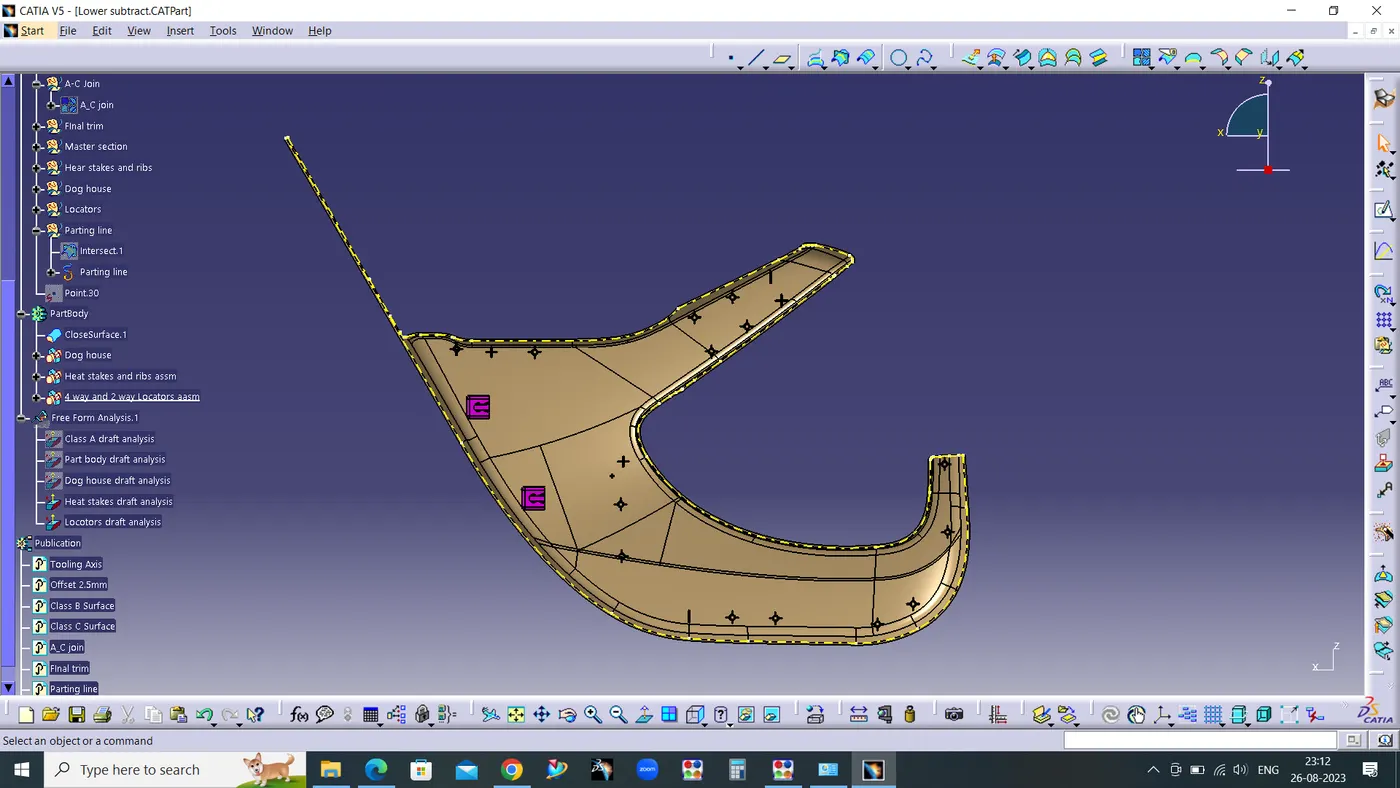
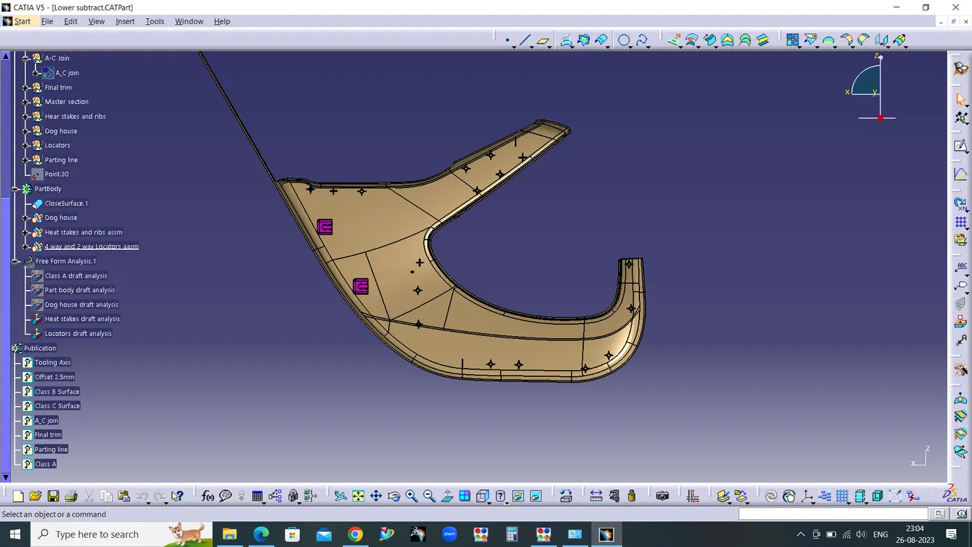
Component views
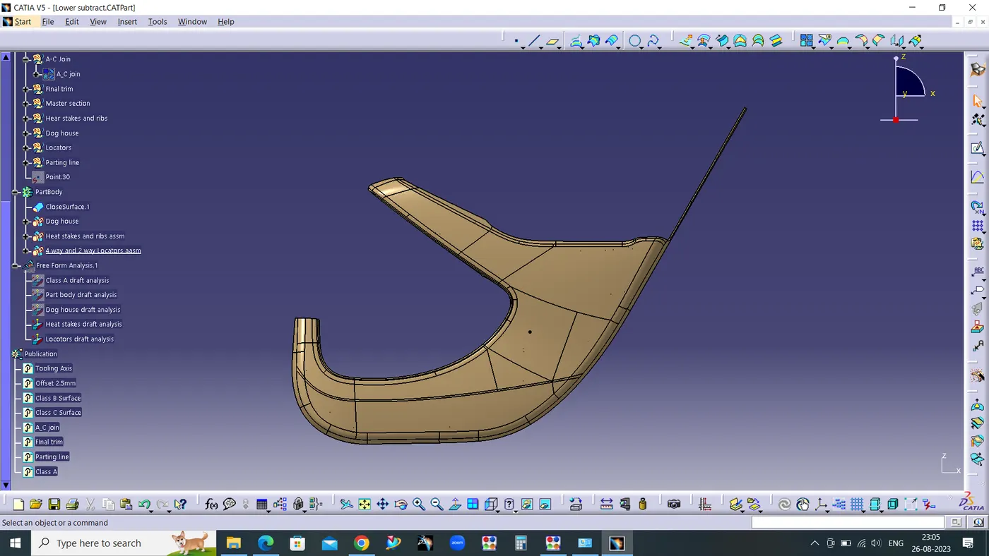
4. Map pocket
Map pocket class A Surface
Procedure for creating the tooling axis
Tooling axis represents the opening and closing of the mold core and cavity during the manufacturing of the components. A plastic product designer should consider the best tooling direction to cutdown the cost of the component very less.
Method opted for creating tooling axis for the door handle
- Check the best tooling direction for the given surface.
- We can find out the best tooling direction by cross checking all the three axes.
- Here we can find out that the best tooling direction for the Arm rest class-A surface is along Y-axis direction.
Creating tooling axis
- We should create a Dummy tooling axis first by creating point and line.
- Extract the existing class A surface and create a dummy tooling axis for reference.Highlighted megentha colour is main tooling axis.
Main tooling Axis
Draft analysis for the given CLASS-A surface
The Draft Analysis is a command enables you to detect if the part you drafted will be easily removed. This type of analysis is performed based on colour ranges identifying zones on the analysed element where the deviation from the draft direction at any point, corresponds to specified values.
Draft analysis is done after determining the tooling axis, draft analysis is used to check whether the minimum draft (3 degrees) is maintained or not.
- Procedure for performing the draft analysis are as follows
- Change the view mode of the component to be in customized parameter mode and then select the shading mode as materials.
- Then open the featured draft analysis tool from the insert menu.
- Then click on use the compass to define the current drafting direction without activation the compass and then activate the compass in the dialogue box drag and align the compass on the Tooling axis.
- Then lock the draft direction and perform draft analysis by clicking on the component.
- The green colour shows the positive daft tooling direction and the given surface passes the draft analysis.
- Click on the analysis under the running point to check the draft analysis on the individual faces. It shows how much draft on specific points when we move the cursor point.
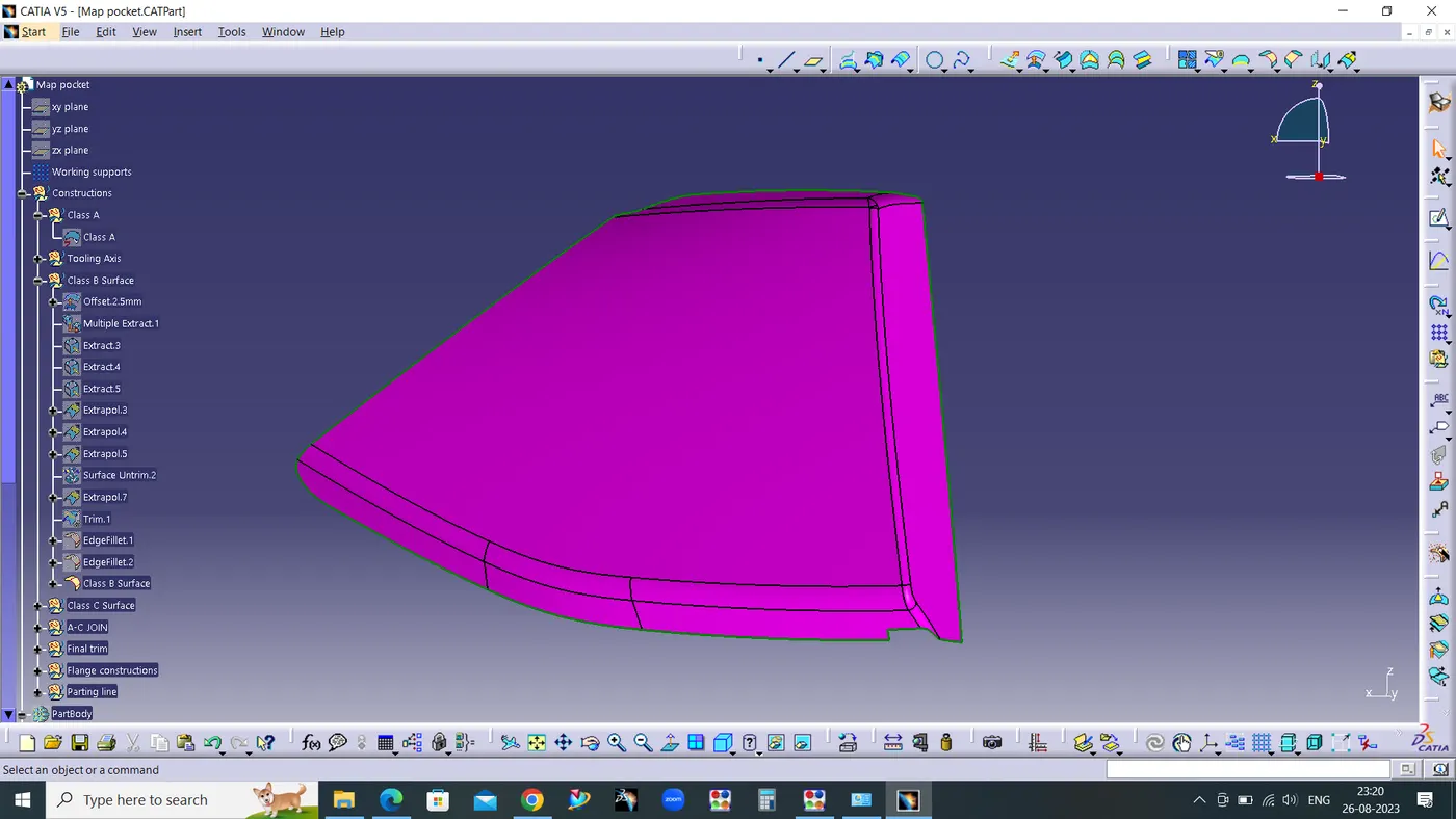
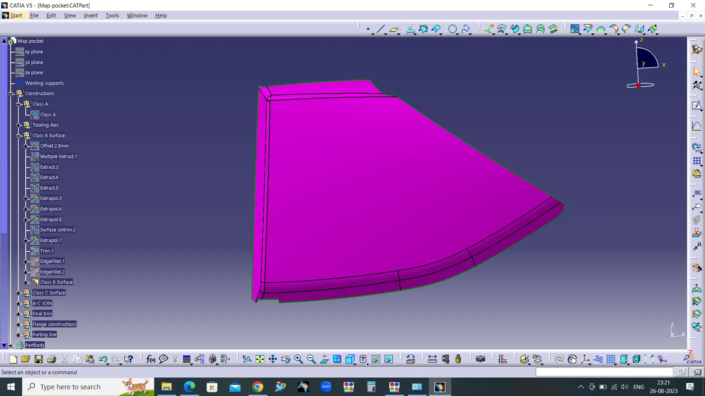
SURFACE-B CREATION
Class-B surface means thickness of a part it is not visible and is inside part. In other words, Class-B surface is a surface below a certain thickness from the class-A surface. This is the surface that contains engineering aspects of a model.
- Offset the class-A surface to 2.5mm inward direction.
- After offset ,There is no patches in the fillet area.
Creation of C Surface
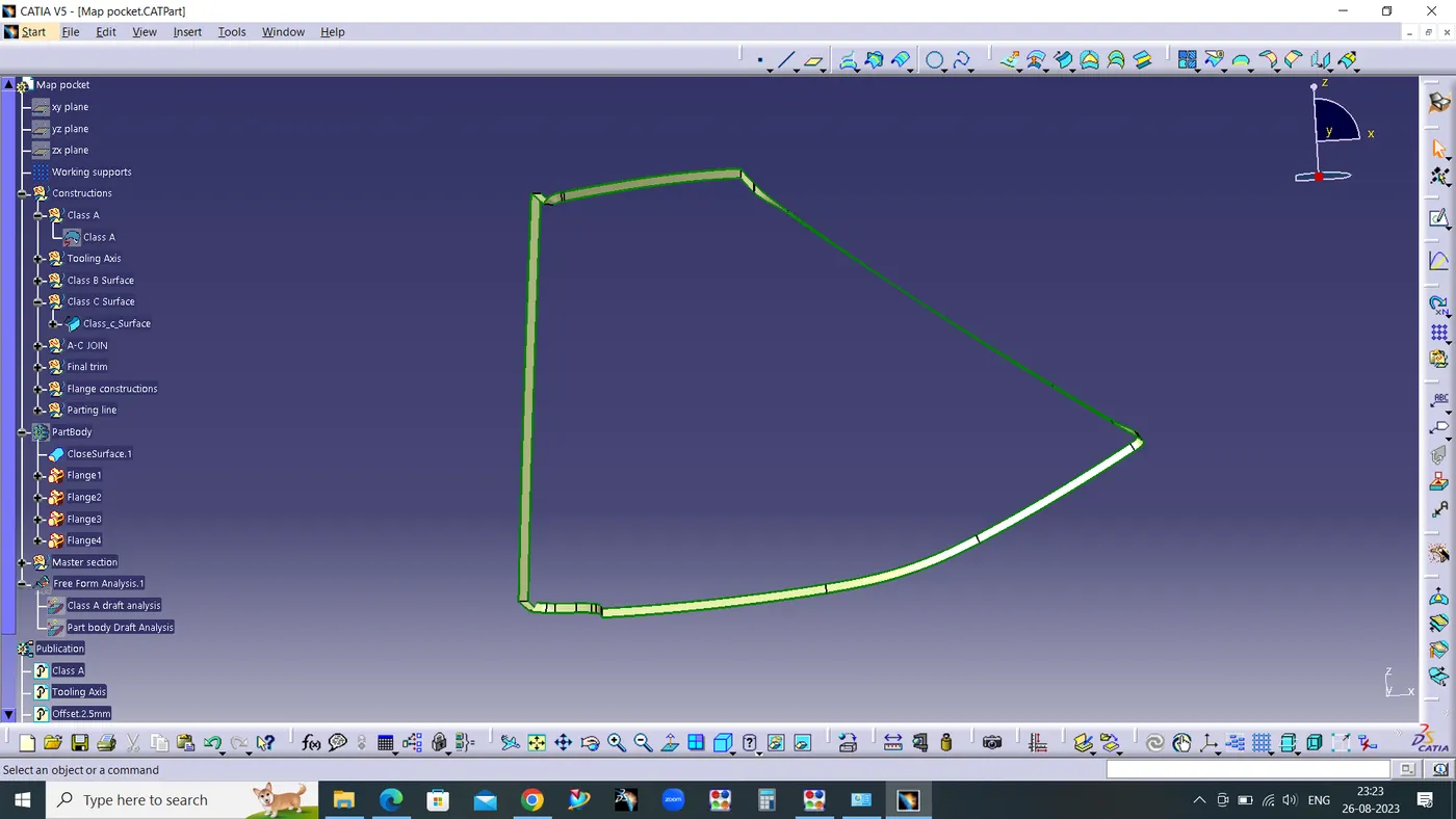
- Surface that joins class-A and class-B surfaces is class-C surface. Class C is often specified for interior surfaces not readily visible, surfaces that will be covered by another part when assembled
- Since it is a class-A surface with sharp corners, we cannot simply create the class-A boundary curve and sweep it at one shot.
- Hence, we need to create smaller boundary and then create sweep,Multi section surface.
- If the surface is perpendicular to the tooling axis we have to provide 3 degree draft with reference to the tooling direction.
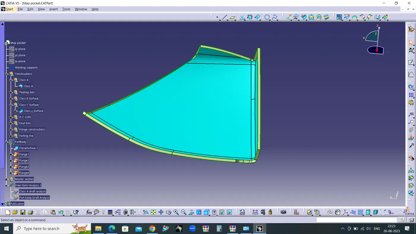
Final A-C JOIN
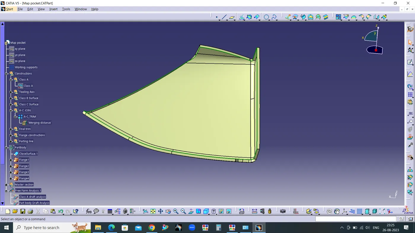
Final A-C & B TRIM
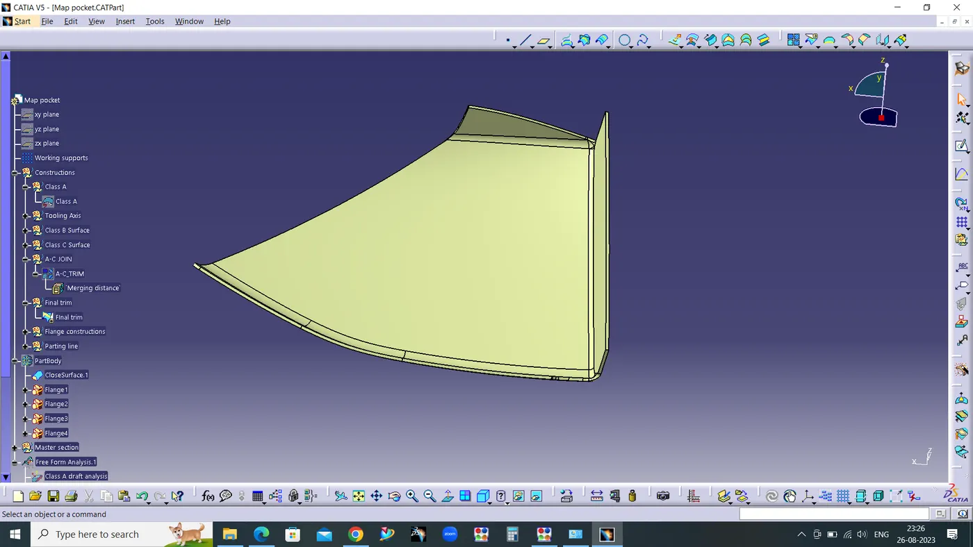
CLosed solid surface
START -> MECHANICAL DESIGN -> PART DESIGN -> SURFACE FEATURE -> CLOSE SURFACE
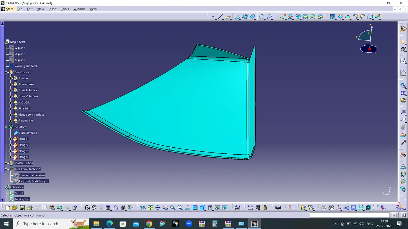
Flange creation using master section
- The thickness of the flange is equal to the thickness of the plastic component that is 2.5 mm
- To use the master section as reference and create the sketch and generate the surface, then make ticken surface.
- The draft provided is 0.5 deg
- Apply requierd fillets on all the sharp edges.
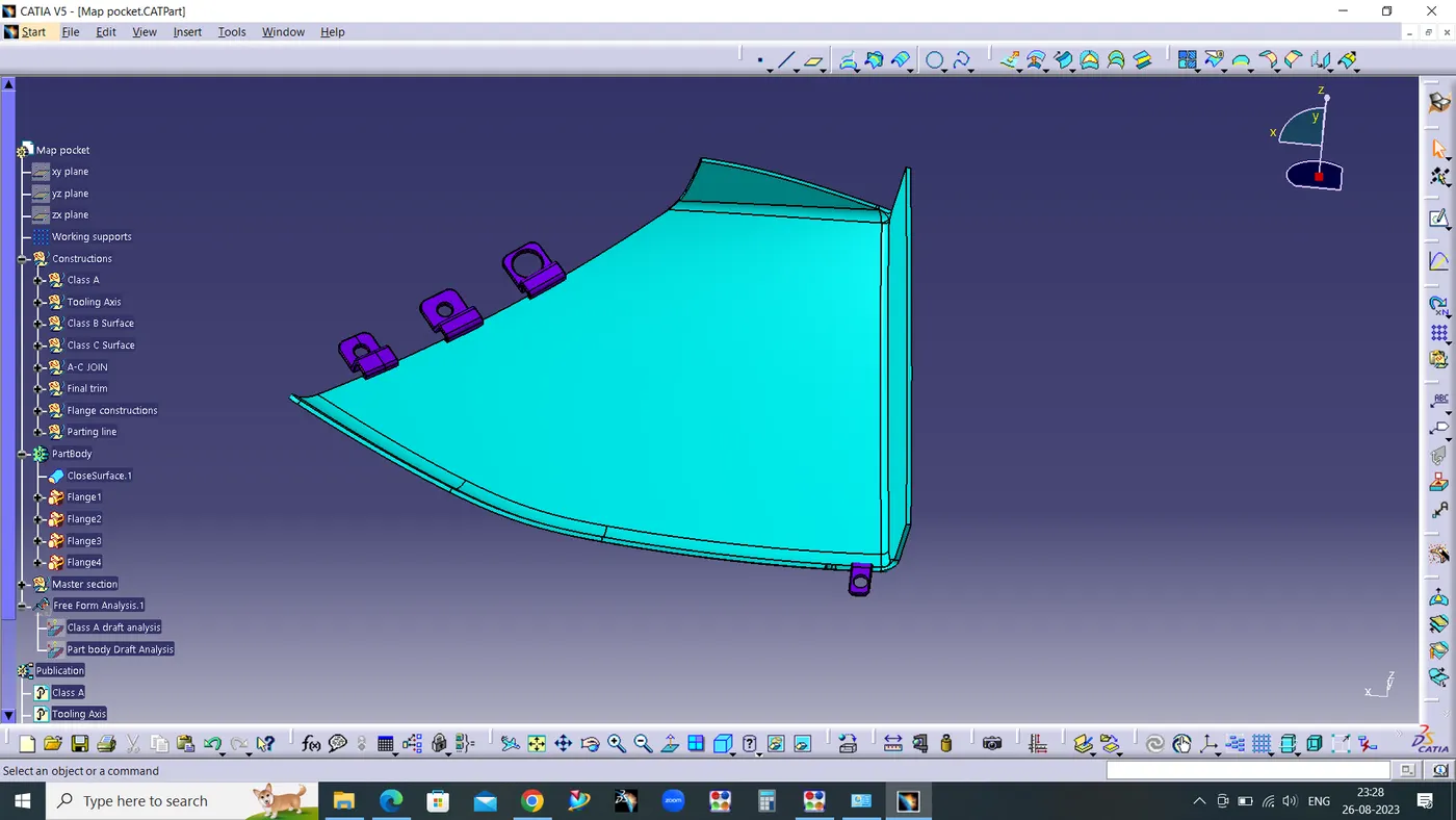
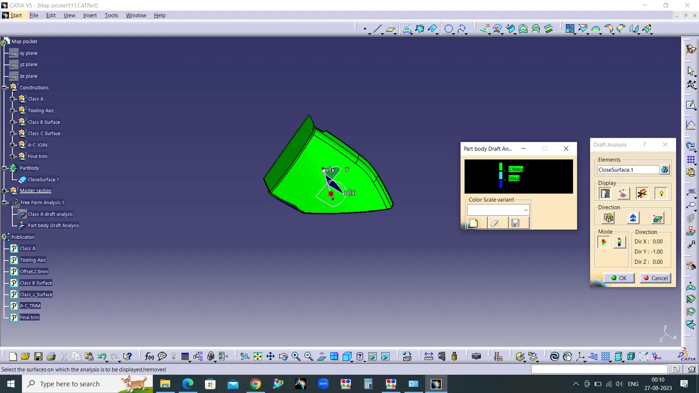
Final Close Body Draft Analysis:
Procedure for performing the draft analysis are as follows
- Change the view mode of the component into customized parameter mode and then select the shading option as material mode.
- Then open the featured draft analysis tool from the insert menu -> Analysis.
- Then click the compass and drag the axis to define the current drafting direction to tooling axis.
- Then lock the draft direction and perform draft analysis by pick the component.
- The green colour shows the positive daft tooling direction and the given surface passes the draft analysis.
5.PUSH PINS-
- Push pins are used for joining one component to another . These are basically attached to the doghouse. For creating the push pins the following reference was taken for dimensions.
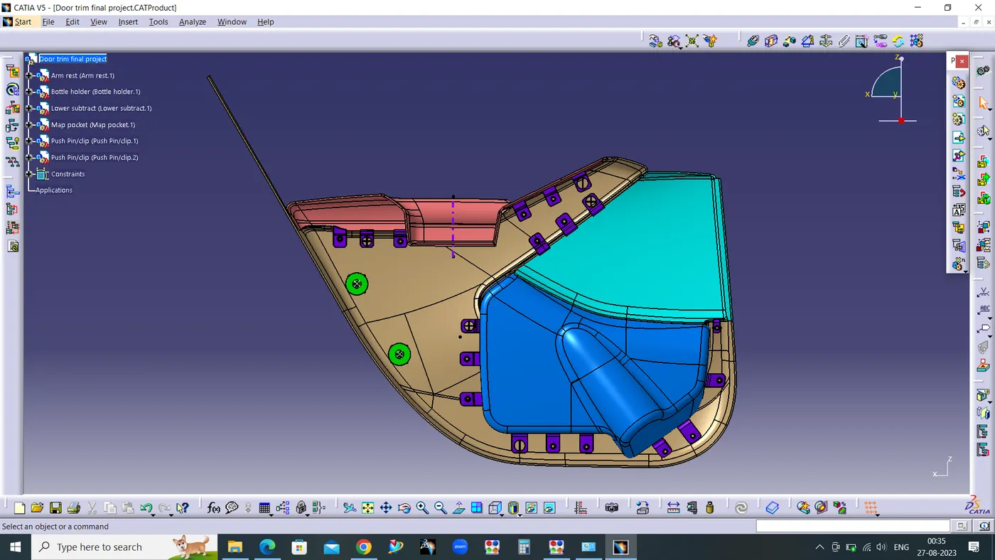
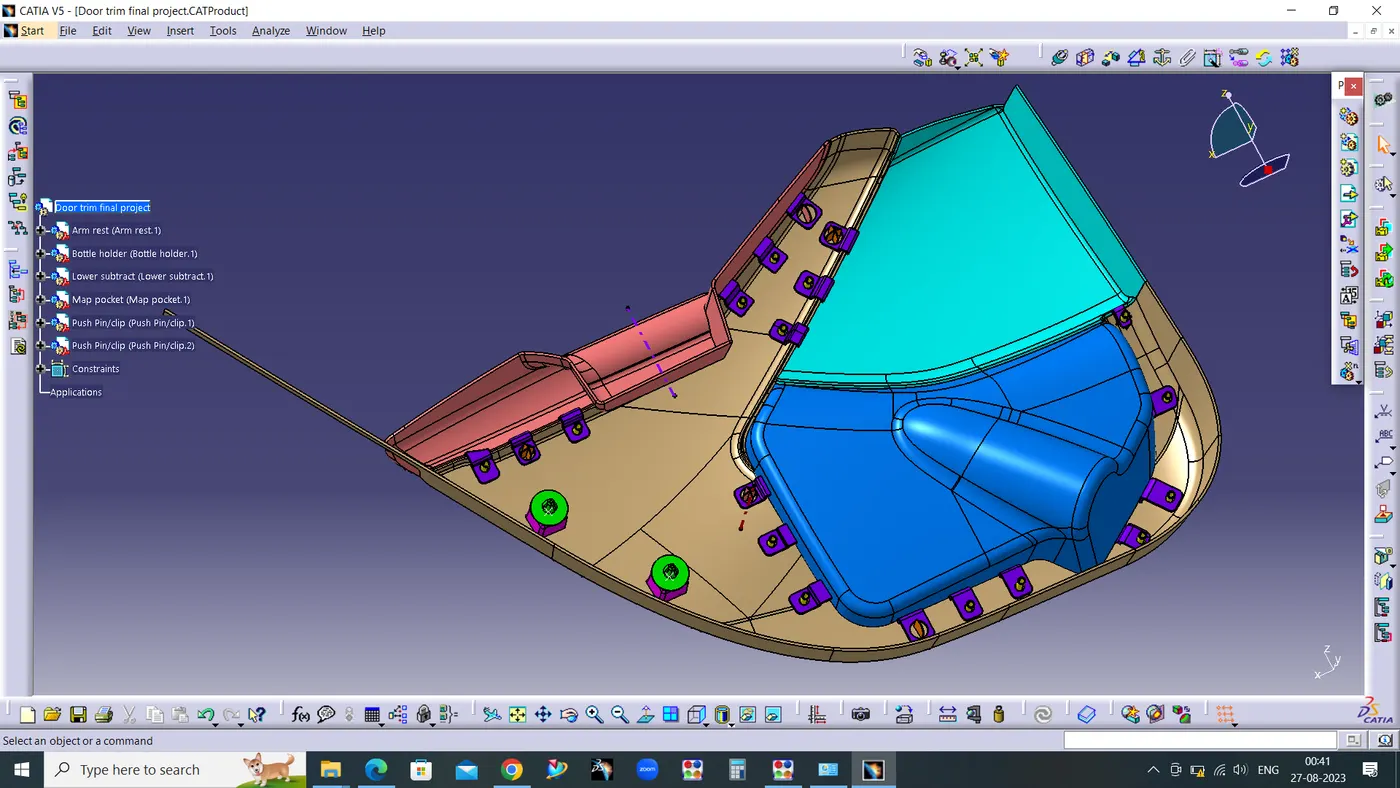
But here the push pin was given,so we need to constain and assemble with the door trim.
Assembly of Door Trim different views:
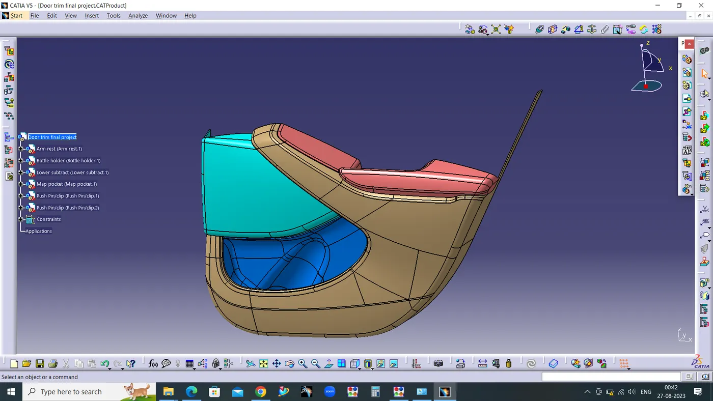
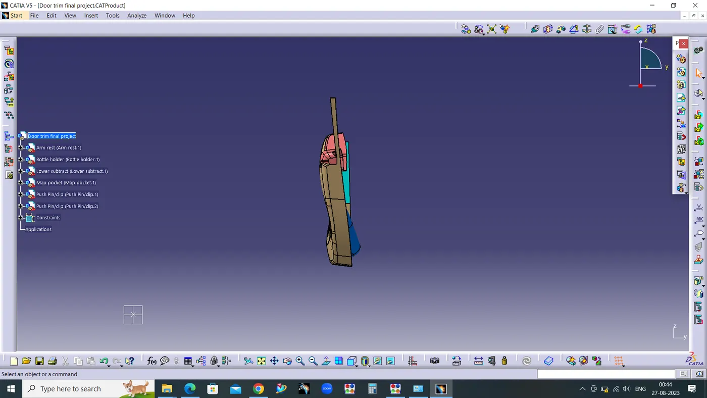
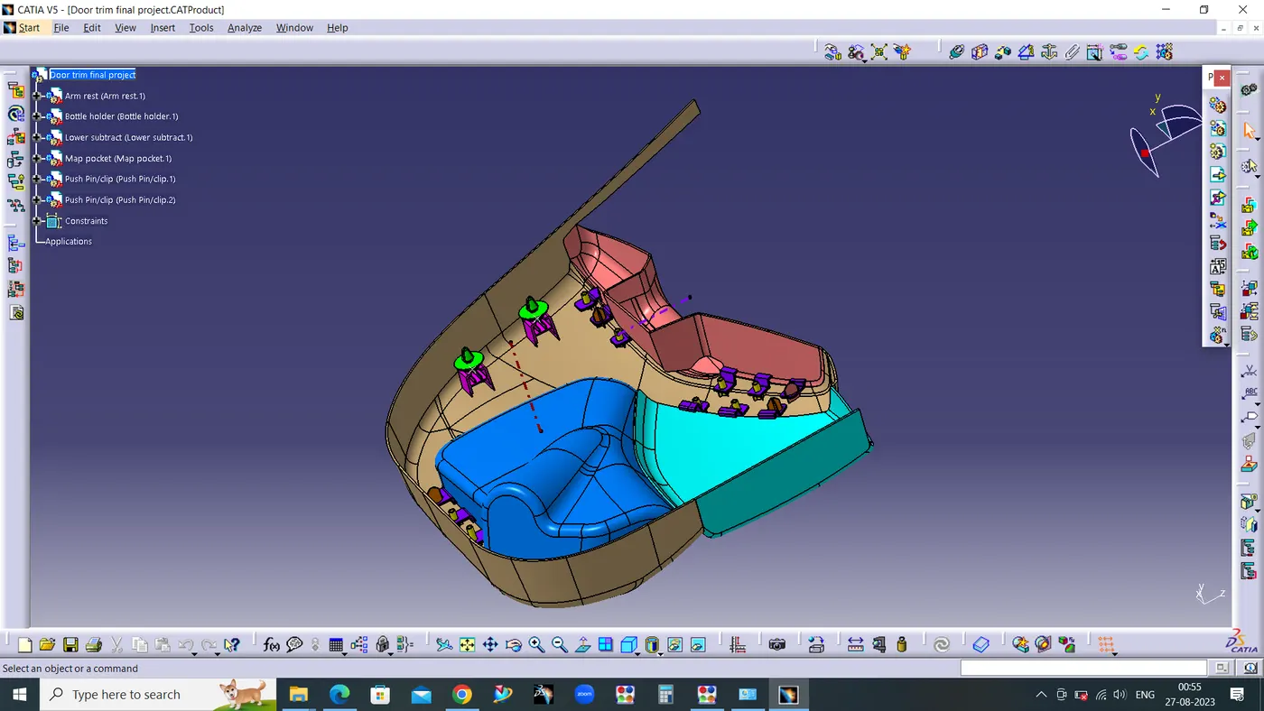
Conclusion:
- Door trim 4 components has been created from given class A to solid body
- Thickened part using the master section for reference was created.
- The mounting features such as 4-way locators, heat stakes, and flanges as per design guidelines were created. In the bottle holder, the flanges are intersecting with the part body despite being created using the design rules, and hence changes in the design of Class A surface are needed.
- Dog houses and the push pins were assembled.
- Draft analysis was performed.